Page is loading ...

SERVICE MANUAL
CONTENTS
1. TECHNICAL CHANGES······································· 3
2. PART NAMES AND FUNCTIONS ····················· 4
3. SPECIFICATION ················································ 5
4. OUTLINES AND DIMENSIONS ························ 7
5. WIRING DIAGRAM ············································ 8
6. REFRIGERANT SYSTEM DIAGRAM ··············· 9
7. SERVICE FUNCTIONS ··································· 10
8. MICROPROCESSOR CONTROL ··················· 12
9. TROUBLESHOOTING ····································· 19
10. DISASSEMBLY INSTRUCTIONS ···················· 32
Models
MSZ-D30NA MSZ-D30NA- 8
MSZ-D36NA MSZ-D36NA- 8
MSY-D30NA MSY-D30NA- 8
MSY-D36NA MSY-D36NA- 8
No. OBH501
REVISED EDITION-C
INDOOR UNIT
Outdoor unit service manual
MUZ-D•NA Series (OBH502)
MUY-D•NA Series (OBH502)
NOTE:
RoHS compliant products have <G> mark on the spec name plate.
PARTS CATALOG (OBB501)
Please void OBH501 REVISED EDITION-B.
Revision C:
• MSZ-D30/D36NA- 8 and
MSY-D30/D36NA-
8 have been added.
DAC-1

2
Revision A:
• 3. SPECIFICATION has been corrected.
Revision B:
• 3. SPECIFICATION has been corrected.
Powerful has been added.
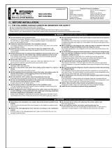
Use the specifi ed refrigerant only
Never use any refrigerant other than that specified.
Doing so may cause a burst, an explosion, or fire when the unit is being used, serviced, or disposed of.
Correct refrigerant is specified in the manuals and on the spec labels provided with our products.
We will not be held responsible for mechanical failure, system malfunction, unit breakdown or accidents caused by
failure to follow the instructions.
Revision C:
• MSZ-D30/D36NA- 8 and MSY-D30/D36NA- 8 have been added.

3
MSZ-D30NA MSZ-D36NA MSY-D30NA MSY-D36NA
1. New model
MSZ-D30NA MSZ-D36NA - 8
1. Electronic control P.C. board has been changed.
MSZ-D36NA MSZ-D36NA - 8
1. Electronic control P.C. board has been changed.
MSY-D30NA MSY-D30NA - 8
1. Electronic control P.C. board has been changed.
MSY-D36NA MSY-D36NA - 8
1. Electronic control P.C. board has been changed.
TECHNICAL CHANGES
1

4
Remote controller
Operation indicator
lamp
Remote control
receiving section
Emergency operation
switch
Horizontal vane
Air outlet
Air filter
(Catechin air filter)
Air inlet
Front panel
Air cleaning filter
(Anti-Allergy Enzyme Filter)
ACCESSORIES
MSZ-D30NA MSZ-D36NA MSY-D30NA MSY-D36NA
MSZ-D30NA
MSZ-D36NA
MSY-D30NA
MSY-D36NA
Installation plate 1
Installation plate screw 4 × 25 mm 7
Remote controller holder 1
Screw for 3.5 × 1.6 mm (Black) 2
Battery (AAA) for remote controller 2
Wireless remote controller 1
Felt tape (Used for left or left-rear piping) 2
L-Joint pipe 1
Conduit plate 1
Air cleaning fi lter 2
PART NAMES AND FUNCTIONS
2

5
Model MSZ-D30NA MSY-D30NA MSZ-D36NA MSY-D36NA
Power supply V, phase, Hz
208/230 , 1 , 60
Max. fuse size (time delay)/ Disconnect switch
A15
Min. circuit ampacity A 1.0
Fan motor F.L.A 0.76
Airfl ow
Low - Med. - High
- Powerful
COOL Dry
(Wet)
CFM
389 - 639 - 848 - 887
(350 - 576 -763 - 798)
HEAT Dry 445 - 639 - 848 - 887 — 445 - 639 - 848 - 887 —
Moisture removal pt./h 9.9 11.3 11.9
Sound level
Low - Med. - High
- Powerful
Cooling
dB(A)
32 - 42 - 49 -51
Heating 34 - 42 - 49 - 50 — 34 - 42 - 49 - 50 —
Cond. drain connection O.D. in. 5/8
Dimensions
W
in.
46-1/16
D 11-5/8
H 14-3/8
Weight Ib. 40
External fi nish Munsell 1.0Y 9.2/0.2
Remote controller Wireless type
Control voltage (by built-in transformer) 12-24 VDC
NOTE : Test conditions are based on AHRI 210/240.
SPECIFICATION
3

6
3-1. OPERATING RANGE
(1) POWER SUPPLY
3-2. OUTLET AIR SPEED AND COVERAGE RANGE
(2) OPERATION
● The air coverage range is the figure up
to the position where the air speed is 1
ft./sec., when air is blown out horizon-
tally from the unit properly at the High
speed position.
The coverage range should be used
only as a general guideline since it var-
ies according to the size of the room
and furniture arranged inside the room.
Mode Condition
Intake air temperature (°F)
Indoor Outdoor
DB WB DB WB
Cooling
Standard temperature 80 67 95 —
Maximum temperature 90 73 115 —
Minimum temperature 67 57 14 —
Maximum humidity 78% —
Heating
Standard temperature 70 60 47 43
Maximum temperature 80 67 75 65
Minimum temperature 70 60 14 13
Model Mode Function Airlow
(CFM)
Air speed
(ft./sec.)
Coverage
range
(ft.)
MSZ-D30NA
MSZ-D36NA HEAT Dry 848 23.6 45.0
MSZ-D30NA
MSZ-D36NA
MSY-D30NA
MSY-D36NA
COOL
Dry 848 23.6 45.0
Wet 763 21.3 40.7
Rated voltage Guaranteed voltage (V)
Indoor unit
208/230 V
1 phase
60 Hz
Min. 187 208 230 Max. 253

7
Unit : inch
MSZ-D30NA MSZ-D36NA MSY-D30NA MSY-D36NA
Wireless remote controller
Piping Insulation
Liquid line
Drain hose
Gas line
Indoor unit
Air out
Air in
45-1/2
46-1/16
14-3/8
2-15/16 33-11/16 9-1/2
2-11/16
2-3/16 20-7/8 17-11/16
Installation plate
Piping
Drain hose
Wall hole ø3
2-5/16 3/4
14-3/8
1-7/8
4-11/16
7/811-5/81-7/8
1/8
5-3/8
5-7/8
2-5/8
2-1/2
2-15/16
ø1-1/4 O.D
ø9/16 I.D
ø1-15/16 O.D
ø1-1/4 I.D
ø3/8 19-11/16
(Flared connection ø3/8)
ø5/8 16-7/8
(Joint connection ø5/8)
Joint
ø1-15/16 O.D
ø1-1/4 I.D
ø5/8
(Flared connection ø5/8)
Inslation
ø
1-1/8 Connected part
ø9/16 O.D
4-11/16 or more 8-11/16 or more
9-3/8 or more
4-3/16 or more
3/8 or more
2-3/16 or more
In case of left,left back,
or left under piping (using spacer) 5-1/8 or more
2-13/16 or more
14-1/2 or more
Required Space (Indoor Unit)
11-5/8 1/4
OUTLINES AND DIMENSIONS
4


9
MSZ-D30NA MSZ-D36NA MSY-D30NA MSY-D36NA
Refrigerant flow in cooling
Refrigerant flow in heating
Unit : inch
Indoor
heat
exchanger
Room temperature
thermistor
RT11
Refrigerant pipe ø5/8
(with heat insulator)
Flared connection
Indoor coil
thermistor
RT12 (Main)
Refrigerant pipe ø3/8
(with heat insulator)
Distributor
Indoor coil
thermistor
RT13 (Sub)
Strainer
Joint
Flared connection
Joint connection
REFRIGERANT SYSTEM DIAGRAM
6

10
7-2. P.C. BOARD MODIFICATION FOR INDIVIDUAL OPERATION
A maximum of 4 indoor units with wireless remote controllers can be used in a room.
In this case, to operate each indoor unit individually by each remote controller, P.C. boards of remote controller must be
modified according to the number of the indoor unit.
7-1. TIMER SHORT MODE
For service, set time can be shortened by short circuit of JPG and JPS the indoor electronic control P.C. board.
The time will be shortened as follows. (Refer to 9-7.)
Set time : 1-minute 1-second
Set time : 3-minute 3-second (It takes 3 minutes for the compressor to start operation. However, the starting time is
shortened by short circuit-of JPG and JPS.)
How to set the remote controller exclusively for particular indoor unit
After you turn the breaker ON, the first remote controller that sends the signal to the indoor unit will be regarded as the remote
controller for the indoor unit.
The indoor unit will only accept the signal from the remote controller that has been assigned to the indoor unit once they are
set.
The setting will be cancelled if the breaker has turned off, or the power supply has shut down.
Please conduct the above setting once again after the power has restored.
How to modify the remote controller P.C. board
Remove batteries before modification.
The board has a print as shown below :
The P.C. board has the print “J1” and “J2”. Solder “J1” and “J2” according to the number of indoor unit as shown in Table 1.
After modification, press the RESET button.
NOTE : For modification, take out
the batteries and press
the OPERATE/STOP (ON/
OFF) button twice or 3
times at first.
After finish modification,
put back the batteries then
press the RESET button.
J2
J1
MSZ-D30NA MSZ-D36NA MSY-D30NA MSY-D36NA
Table 1
1 unit operation 2 units operation 3 units operation 4 units operation
No. 1 unit No modifi cation Same as at left Same as at left Same as at left
No. 2 unit — Solder J1 Same as at left Same as at left
No. 3 unit — — Solder J2 Same as at left
No. 4 unit — — — Solder both J1 and J2
SERVICE FUNCTIONS
7

11
7-3. AUTO RESTART FUNCTION
When the indoor unit is controlled with the remote controller, the operation mode, the set temperature, and the fan speed
are memorized by the indoor electronic control P.C. board. “AUTO RESTART FUNCTION” automatically starts operation
in the same mode just before the shut-off of the main power.
Operation
If the main power has been cut, the operation settings remain.
After the power is restored, the unit restarts automatically according to the memory.
(However, it takes at least 3 minutes for the compressor to start running.)
How to release “AUTO RESTART FUNCTION”
Turn off the main power of the unit.
Solder the Jumper wire JR07 on the indoor electronic control P.C. board. (Refer to 9-7.)
NOTE:
• The operation settings are memorized when 10 seconds have passed after the indoor unit was operated with the
remote controller.
• If main power is turned OFF or a power failure occurs while AUTO START/STOP timer is active, the timer setting is
cancelled.
• If the unit has been off with the remote controller before power failure, the auto restart function does not work as the
power button of the remote controller is off.
• To prevent breaker off due to the rush of starting current, systematize other home appliance not to turn on at the
same time.
• When some air conditioners are connected to the same supply system, if they are operated before power failure, the
starting current of all the compressors may flow simultaneously at restart.
Therefore, the special counter-measures are required to prevent the main voltage-drop or the rush of the starting
current by adding to the system that allows the units to start one by one.
JR07
CN151
CN152
CN101
CN211CN112
BZ

12
NOTE: Last setting will be stored after the unit is turned OFF with the remote controller. Indoor unit receives the signal of the
remote controller with beeps.
WIRELESS REMOTE CONTROLLER
.)
Signal transmitting section
Operation display section
Temperature buttons
OPERATE/STOP
(ON/OFF) button
NOTE
Use the remote controller
provided with the unit only.
Do not use other remote
controller.
Indication of
remote controller
model is on back
OPERATION SELECT button
ECONO COOL button ON TIMER button
CLOCK SET button
TIME SET buttons
FORWARD button
BACKWARD button
OFF TIMER button
RESET button
POWERFUL button
These pictures show MSZ type.
WIDE VANE button (Vertical vane button)
FAN SPEED
CONTROL button
VANE CONTROL button
(Horizontal vane button)
MSZ-D30NA MSZ-D36NA MSY-D30NA MSY-D36NA
Operation Indicator lamp
The operation indicator at the right side of the indoor unit indicates the operation state.
•The following indication applies regardless of shape of the indication.
Indication Operation state Room temperature
The unit is operating to
reach the set temperature
About 4°F (2°C) or more
away from set tempera-
ture
The room temperature is
approaching the set tem-
perature
About 2°F (1°C) to 4°F (2
°C) from set temperature
INDOOR UNIT DISPLAY SECTION
Lighted
Blinking
Not lighted
MICROPROCESSOR CONTROL
8

13
8-1. COOL ( ) OPERATION
(1) Press OPERATE/STOP (ON/OFF) button.
OPERATION INDICATOR lamp of the indoor unit turns on with a beep tone.
(2) Select COOL mode with OPERATION SELECT button.
(3) Press TEMPERATURE buttons (TOO WARM or TOO COOL button) to select the desired temperature.
The setting range is 61 ~ 88°F (16 ~ 31°C).
1. Coil frost prevention
When the temperature of indoor heat exchanger becomes too low, the coil frost prevention mode works.
The indoor fan operates at the set speed and the compressor stops. This mode continues until the temperature of indoor
heat exchanger rises.
2. Low outside temperature operation
When the outside temperature is lower, low outside temperature operation starts, and the outdoor fan slows or stops.
8-2. DRY ( ) OPERATION
(1) Press OPERATE/STOP (ON/OFF) button.
OPERATION INDICATOR lamp of the indoor unit turns on with a beep tone.
(2) Select DRY mode with OPERATION SELECT button.
(3) The set temperature is determined from the initial room temperature.
1. Coil frost prevention
Coil frost prevention is as same as COOL mode. (8-1.1.)
2. Low outside temperature operation
Low outside temperature operation is as same as COOL mode. (8-1.2.)
8-3. HEAT ( ) OPERATION (MSZ)
(1) Press OPERATE/STOP (ON/OFF) button.
OPERATION INDICATOR lamp of the indoor unit turns on with a beep tone.
(2) Select HEAT mode with OPERATION SELECT button.
(3) Press TEMPERATURE buttons (TOO WARM or TOO COOL button) to select the desired temperature.
The setting range is 61 ~ 88°F (16 ~ 31°C).
1. Cold air prevention control
When the compressor is not operating or is starting, and the temperature of indoor heat exchanger and/or the room tem-
perature is low or when defrosting is being done, the indoor fan will stop or rotate in Very Low speed.
2. High pressure protection
The compressor operational frequency is controlled by the temperature of the indoor heat exchanger to prevent the con-
densing pressure from increasing excessively.
When the temperature of indoor heat exchanger becomes too high, the high pressure protection works.
The indoor fan operates following the cold air prevention control. This mode continues until the temperature of indoor heat
exchanger falls.
3. Defrosting
Defrosting starts when the temperature of outdoor heat exchanger becomes too low.
The compressor stops once, the indoor/outdoor fans stop, the 4-way valve reverses and the compressor re-starts.
This mode continues until the temperature of outdoor heat exchanger rises or the fixed time passes.
8-4. FAN ( ) OPERATION (MSY)
(1) Press OPERATE/STOP (ON/OFF) button.
OPERATION INDICATOR lamp of the indoor unit turns ON with a beep tone.
(2) Select FAN mode with OPERATION SELECT button.
(3) Select the desired fan speed. When AUTO, it becomes Low.
Only indoor fan operates. Outdoor unit does not operate.
8-5. “I FEEL CONTROL” ( ) OPERATION (MSY)
(1) Press OPERATE/STOP (ON/OFF) button on the remote controller.
OPERATION INDICATOR lamp of the indoor unit turns on with a
beep tone.
(2) Select “I FEEL CONTROL” mode with OPERATION SELECT button.
(3) The operation mode is determined by the room temperature at start-
up of the operation.
• Once the mode is fixed, the mode does not change by room temperature afterwards.
• Under the ON TIMER ( ) operation, mode is determined according to the room temperature at the set time the
operation starts.
Initial room temperature Mode
77°F (25°C) or more COOL mode of
"I FEEL CONTROL"
More than 55°F (13°C),
less than 77°F (25°C)
DRY mode of
"I FEEL CONTROL"

14
(4) The initial set temperature is decided by the initial room temperature.
Model Initial room temperature Initial set temperature
COOL mode of "I FEEL
CONTROL"
79°F (26°C) or more 75°F (24°C)
1
77°F (25°C) to 79°F (26°C) Initial room temperature minus 4°F (2°C)
DRY mode of "I FEEL
CONTROL"
More than 55°F (13°C),
less than 77°F (25°C) Initial room temperature minus 4°F (2°C)
1 When the system is restarted with the remote controller, the system operates with the previous set temperature
regardless of room temperature at restart.
The set temperature is calculated by the previous set temperature.
(5) TEMPERATURE buttons
In “I FEEL CONTROL” ( ) mode, set temperature is decided by the microprocessor based on the room temperature.
In addition, set temperature can be controlled by TOO WARM or TOO COOL buttons when you feel too cool or too
warm.
Each time the TOO WARM or TOO COOL button is pressed, the indoor unit receives the signal and emits a beep tone.
• Fuzzy control
When the TOO COOL or TOO WARM button is pressed, the microprocessor changes the set temperature, considering
the room temperature, the frequency of pressing TOO COOL or TOO WARM button and the user’s preference to heat or
cool. So this is called “Fuzzy control”, and works only in “I FEEL CONTROL” mode.
In DRY mode of “I FEEL CONTROL”, the set temperature doesn’t change.
··· To raise the set temperature 2 ~ 4°F (1 ~ 2°C)
··· To lower the set temperature 2 ~ 4°F (1 ~ 2°C)
8-6. AUTO CHANGE OVER ··· AUTO MODE OPERATION (MSZ)
Once desired temperature is set, unit operation is switched automatically between COOL and HEAT operation.
Mode selection
(1) Initial mode
When unit starts the operation with AUTO operation from off;
• If the room temperature is higher than the set temperature, operation starts in COOL mode.
• If the room temperature is equal to or lower than the set temperature, operation starts in HEAT mode.
(2) Mode change
COOL mode changes to HEAT mode when about 15 minutes have passed with the room temperature 4°F (2°C) below
the set temperature.
HEAT mode changes to COOL mode when about 15 minutes have passed with the room temperature 4°F (2°C) above
the set temperature.

15
8-7. AUTO VANE OPERATION
1. Horizontal vane
(1) Vane motor drive
These models are equipped with a stepping motor for the horizontal vane. The rotating direction, speed, and angle of
the motor are controlled by pulse signals (approximately 12 V) transmitted from indoor microprocessor.
(2) The horizontal vane angle and mode change as follows by pressing VANE CONTROL button.
(3) Positioning
To confirm the standard position, the vane moves until it touches the vane stopper. Then the vane is set to the selected
angle.
(a) The operation starts or finishes (including timer operation).
(b) The test run starts.
(4) VANE AUTO ( ) mode
The microprocessor automatically determines the horizontal vane angle and operation to make the optimum room tem-
perature distribution.
(5) STOP (operation OFF) and ON TIMER standby
In the following cases, the horizontal vane returns to the closed position.
(a) OPERATE/STOP (ON/OFF) button is pressed (POWER OFF).
(b) The operation is stopped by the emergency operation.
(c) ON TIMER is ON standby.
(6) Dew prevention
During COOL or DRY operation with the vane angle at Angle 4 ~ 5 when the compressor cumulative operation time
exceeds 1 hour, the vane angle automatically changes to Angle 1 for dew prevention.
(7) SWING ( ) mode
By selecting SWING mode with VANE CONTROL button, the horizontal vane swings vertically.
(8) Cold air prevention in HEAT operation (MSZ)
The horizontal vane position is set to Upward.
(9) ECONO COOL ( ) operation (ECONOmical operation)
When ECONO COOL button is pressed in COOL mode, set temperature is automatically set 3.6°F (2°C) higher.
Also the horizontal vane swings in various cycle.
SWING operation makes you feel cooler than set temperature. So, even though the set temperature is higher, the air
conditioner can keep comfort. As a result, energy can be saved.
To cancel this operation, select a different mode or press one of the following buttons in ECONO COOL operation:
ECONO COOL, VANE CONTROL or POWERFUL button.
(
10
) POWERFUL ( ) operation.
The air conditioner automatically adjusts the fan speed and the set temperature, and operates the POWERFUL mode.
The POWERFUL mode is cancelled automatically 15 minutes after operation starts, or when POWERFUL but-
ton is pressed once again within 15 minutes after operation starts. The operation mode returns to the mode prior to
POWERFUL operation. To manually cancel this operation, select a different mode or press one of the following buttons:
ECONO COOL or FAN SPEED.
1
COOL and DRY operation
FAN operation (MSY)
Vane angle is fixed to Angle 1.
HEAT operation (MSZ)
Vane angle is fixed to Angle 4.

16
2. Vertical vane
(1) Vane motor drive
These models are equipped with a stepping motor for the vertical vane. The rotating direction, speed, and angle of the
motor are controlled by pulse signals (approximately 12 V) transmitted from microprocessor.
(2) The vertical vane angle and mode change as follows by pressing WIDE VANE button.
(3) Positioning
To confirm the standard position, the vane moves until it touches the vane stopper.
Then the vane is set to the desired angle.
Confirming of standard position is performed.
(a) OPERATE/STOP (ON/OFF) button is pressed (POWER ON/OFF).
(b) SWING is started or finished.
(c) The power supply turns ON.
(4) SWING MODE ( )
By selecting SWING mode with WIDE VANE button, the vertical vane swings horizontally.
The remote controller displays “ ”.
(5) WIDE MODE ( )
By selecting WIDE mode with WIDE VANE button, indoor fan speed becomes faster than setting fan speed on the
remote controller ( ). The remote controller displays “ ”.
NOTE : The position of vane angle 3, angle 4 and angle 5 are different in COOL operation and HEAT operation.
Indoor fan speed becomes faster than setting fan speed on the remote controller even when or is select-
ed.
61 23
45SWING

17
8-8. TIMER OPERATION
1. How to set the time
(1) Check that the current time is set correctly.
NOTE : Timer operation will not work without setting the current time. Initially “0:00” blinks at the current time display
of TIME MONITOR, so set the current time correctly with CLOCK SET button.
How to set the current time
(a) Press the CLOCK set button.
(b) Press the TIME SET buttons ( and ) to set the current time.
• Each time FORWARD button (
) is pressed, the set time increases by 1 minute, and each time
BACKWARD button ( ) is pressed, the set time decreases by 1 minute.
• Pressing those buttons longer, the set time increases/decreases by 10 minutes.
(c) Press the CLOCK set button.
(2) Press OPERATE/STOP (ON/OFF) button to start the air conditioner.
(3) Set the time of timer.
ON timer setting
(a) Press ON TIMER button ( ) during operation.
(b) Set the time of the timer using TIME SET buttons ( and ) .
OFF timer setting
(a) Press OFF TIMER button ( ) during operation.
(b) Set the time of the timer using TIME SET buttons ( and ).
Each time FORWARD button ( ) is pressed, the set time increases by 10 minutes; each time BACKWARD button (
) is pressed, the set time decreases by 10 minutes.
2. To release the timer
To release ON timer, press ON TIMER button ( ).
To release OFF timer, press OFF TIMER button ( ).
TIMER is cancelled and the display of set time disappears.
(Example 1) The current time is 8:00 PM.
The unit turns off at 11:00 PM, and on at 6:00 AM.
• OFF timer and ON timer can be used in combination. The timer of the set time that is reached first will operate first.
• “ ” and “ ” display shows the order of OFF timer and ON timer operation.
PROGRAM TIMER
(Example 2) The current time is 11:00 AM.
The unit turns on at 5:00 PM, and off at 9:00 PM.
PM
AM
PM
PM
NOTE : If the main power is turned OFF or a power failure occurs while ON/OFF timer is active, the timer setting is can-
celled. As these models are equipped with an auto restart function, the air conditioner starts operating with timer
cancelled when power is restored.

18
EMERGENCY OPERATION switch
E.O.
SW
E.O.
SW
8-9. EMERGENCY/TEST OPERATION
In case of test run operation or emergency operation, use EMERGENCY OPERATION switch on the front of the indoor
unit. Emergency operation is available when the remote controller is missing, has failed or the batteries of the remote
controller run down. The unit will start and OPERATION INDICATOR lamp will light.
The first 30 minutes of operation is the test run operation. This operation is for servicing. The Indoor fan speed runs at
High speed and the temperature control does not work.
After 30 minutes of test run operation the system shifts to EMERGENCY COOL/HEAT MODE with a set temperature of
75°F (24°C). The fan speed shifts to Med.
The coil frost prevention works even in the test run or the emergency operation.
In the test run or emergency operation, the horizontal vane operates in VANE AUTO ( ) mode.
Emergency operation continues until EMERGENCY OPERATION switch is pressed once or twice or the unit receives any
signal from the remote controller. In case of latter normal operation will start.
NOTE : Do not press EMERGENCY OPERATION switch during normal operation.
8-11. CHANGING TEMPERATURE INDICATION (°F /°C)
8-10. 3-MINUTE TIME DELAY OPERATION
When the system turns OFF, compressor will not restart for 3 minutes as 3-minute time delay function operates to protect
compressor from overload.
The preset unit is °F.
°F→°C : Press RESET button while the
temperature buttons are pressed.
°C→°F : Press RESET button or remove
the batteries.
•
•
•
Press RESET button gently using
a thin instrument.
Operation mode COOL HEAT
(MUZ)
Set temperature 75°F (24°C) 75°F (24°C)
Fan speed Med. Med.
Horizontal vane Auto Auto
The operation mode is indicated by the Operation
Indicator lamp as following
Operation Indicator lamp
(MSZ type)
EMERGENCY COOL
↓
EMERGENCY HEAT
↓
STOP
(MSY type)
EMERGENCY COOL
↓
STOP
Lighted
Not lighted

19
9-1. CAUTIONS ON TROUBLESHOOTING
1. Before troubleshooting, check the following
1) Check the power supply voltage.
2) Check the indoor/outdoor connecting wire for miswiring.
2. Take care of the following during servicing
1) Before servicing the air conditioner, be sure to turn off the unit first with the remote controller, and then after confirm-
ing the horizontal vane is closed, turn off the breaker and/or disconnect the power plug.
2) Be sure to turn OFF the power supply before removing the front panel, the cabinet, the top panel, and the electronic
control P.C. board.
3) When removing the electronic control P.C. board, hold the edge of the board with care NOT to apply stress on the
components.
4) When connecting or disconnecting the connectors, hold the housing of the connector. DO NOT pull the lead wires.
3. Troubleshooting procedure
1) First, check if the OPERATION INDICATOR lamp on the indoor unit is flashing on and off to indicate an abnormality.
To make sure, check how many times the OPERATION INDICATOR lamp is flashing on and off before starting service
work.
2) Before servicing, check that the connector and terminal are connected properly.
3) When the electronic control P.C. board seems to be defective, check the copper foil pattern for disconnection and the
components for bursting and discoloration.
4) When troubleshooting, refer to 9-2., 9-3. and 9-4.
4. How to replace batteries
Weak batteries may cause the remote controller malfunction.
In this case, replace the batteries to operate the remote controller normally.
Lead wiring Housing point
<Incorrect> <Correct>
MSZ-D30NA MSZ-D36NA MSY-D30NA MSY-D36NA
RESET button
Insert the negative pole of the
batteries first. Check if the polarity
of the batteries is correct.
NOTE : 1. If RESET button is not pressed, the remote controller may not operate correctly.
2. This remote controller has a circuit to automatically reset the microcomputer when batteries are replaced.
This function is equipped to prevent the microcomputer from malfunctioning due to the voltage drop caused by the
battery replacement.
3. Do not use the leaking batteries.
Press RESET button with a thin instrument, and
then use the remote controller.
Remove the front lid and insert batteries.
Then reattach the front lid.
TROUBLESHOOTING
9

20
Outline of the function
This air conditioner can memorize the abnormal condition which has occurred once.
Even though LED indication listed on the troubleshooting check table (9-4.) disappears, the memorized failure details can
be recalled.
This mode is very useful when the unit needs to be repaired for the abnormality which does not recur.
9-2. FAILURE MODE RECALL FUNCTION
1. Flow chart of failure mode recall function for the indoor/outdoor unit
Does the left lamp of OPERATION INDICATOR
lamp on the indoor unit blink at the interval of 0.5
seconds?
Blinks: Either indoor or outdoor unit is abnormal.
Beep is emitted at the same timing as the
blinking of the left lamp of OPERATION
INDICATOR lamp. 2
Indoor unit is normal.
But the outdoor unit might be abnormal because there are some abnor-
malities that can't be recalled with this way.
Confi rm if outdoor unit is abnormal according to the detailed outdoor unit
failure mode recall function.
No
Yes
The cause of abnormality cannot be found because the abnormality does not recur.
Setting up the failure mode recall function
Turn ON the power supply.
<Preparation of the remote controller>
While pressing both OPERATION SELECT button and TOO COOL button on the
remote controller at the same time, press RESET button.
First, release RESET button.
Hold down the other two buttons for another 3 seconds. Confi rm all the indicators on
the LCD screen of the remote controller are displayed. Then release the buttons.
Press OPERATE/STOP (ON/OFF) button of the remote controller (the set temperature is
displayed) with the remote controller headed towards the indoor unit. 1
Judgment of indoor/outdoor abnormality
Before blinking, does the left lamp of OP-
ERATION INDICATOR lamp stay ON for 3
seconds?
Stays ON for 3 seconds (without beep):
The outdoor unit is abnormal.
The indoor unit is abnormal.
Check the blinking pattern, and confi rm the abnormal point with the indoor unit
failure mode table. (Refer to 9-2.2)
Make sure to check at least two consecutive blinking cycles. 2
Releasing the failure mode recall function
Release the failure mode recall function by the following procedures.
Turn OFF the power supply and turn it ON again.
Press RESET button of the remote controller.
•
•
The outdoor unit is abnormal.
Check the blinking pattern, and confi rm the abnormal point with the
outdoor unit failure mode table. (Refer to outdoor unit service manual.)
Make sure to check at least two consecutive blinking cycles. 3
Repair the defective parts.
Deleting the memorized abnormal condition
After repairing the unit, recall the failure mode again according to "Setting up the failure mode recall
function" mentioned above.
Press OPERATE/STOP (ON/OFF) button of the remote controller (the set temperature is displayed)
with the remote controller headed towards the indoor unit.
Press EMERGENCY OPERATION switch so that the memorized abnormal condition is deleted.
Release the failure mode recall function according to "Releasing the failure mode recall function"
mentioned above.
Operational procedure
Yes
(Blinks)
No
(OFF)
NOTE: 1. Make sure to release the failure mode recall function once it is set up, otherwise the unit cannot operate properly.
2. If the abnormal condition is not deleted from the memory, the last abnormal condition is kept memorized.
1. Regardless of normal or abnormal condition, a short
beep is emitted once the signal is received.
2. Blinking pattern when the indoor unit is abnormal:
3.Blinking pattern when the outdoor unit is abnormal:
ON
OFF
Beeps
Repeated cycle Repeated cycle
ON
OFF
No beep Beeps
Repeated cycle
2.5-second OFF
Blinking at 0.5-
second interval
2.5-second OFF 3-second ON
Blinking at 0.5-
second interval
Beeps
Repeated cycle
2.5-second OFF
Blinking at 0.5-
second interval
No beep Beeps
Repeated cycle
2.5-second OFF 3-second ON
Blinking at 0.5-
second interval
Repeated cycle
Beeps
/