Page is loading ...

1
Betriebsanleitung
Filtermodul AC-FM-AR
Technische Änderungen vorbehalten, alle Angaben ohne Gewähr. © EUCHNER GmbH + Co. KG 2127461‑03‑09/19 (Originalbetriebsanleitung)
DE Bestimmungsgemäßer Gebrauch
Das Gerät dient zum Filtern von Testimpulsen auf
den Sicherheitsausgängen von EUCHNER‑Geräten
mit OSSD‑Ausgängen. Das Gerät darf nur für diesen
Zweck verwendet werden.
WARNUNG!
Durch das Filtern der Testimpulse ist an den Sicher‑
heitsausgängen FO1A* / FO1B* des Filtermoduls
die Querschlussüberwachung nicht mehr wirksam.
Treffen Sie geeignete Maßnahmen um ab den Si‑
cherheitsausgängen FO1A* / FO1B*Querschlüsse
auszuschließen (z.B. geschützte Leitungsverlegung
oder Montage im gleichen Schaltschrank, wie die
Steuerung).
Allgemeine Sicherheitshinweise
Montage, elektrischer Anschluss und Inbetriebnahme
ausschließlich durch autorisiertes Fachpersonal mit
folgenden Kenntnissen:
fSpezielle Kenntnisse im Umgang mit Sicherheits‑
bauteilen
fKenntnis der geltenden EMV‑Vorschriften
fKenntnis der geltenden Vorschriften zur Arbeitssi‑
cherheit und Unfallverhütung.
Funktion
Die Testimpulse bei Geräten mit OSSD‑Ausgängen
dienen der Querschlussüberwachung der Sicherheits‑
ausgänge. Die Sicherheitsausgänge dieser Geräte
werden an eine sichere Steuerung angeschlossen.
Einige Steuerungen interpretieren diese Testimpulse
als Schaltsignal.
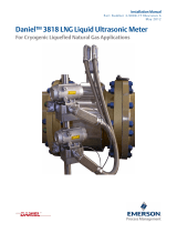
Um diese Probleme zu vermeiden wird das Filtermodul
zwischen den Sicherheitsausgängen des Gerätes und
den Sicherheitseingängen der Steuerung angeschlos‑
sen (siehe Bild 1: Anschlussschema ).
Die Testimpulse des angeschlossenen Gerätes wer‑
den dabei soweit herausgeltert, dass die Eingänge
der Steuerung diese nicht mehr wahrnehmen.
Das Gerät hat keinen eigenen PL / Kategorie nach
ENISO13849‑1.
Das Gerät verfügt über zwei Status‑LEDs (grün) und
zwei Diagnose‑LEDs (rot).
FI1A
FI1B FO1B*
FO1A*
GND
LEDs
Channel B
Channel A
RD
GN
RD
GN
LED-Signal Bedeutung
grün, an Sicherheitsausgänge FO1A* / FO1B* sind durchge‑
schaltet und geltert.
grün, aus ‑ Kein Signal an den Sicherheitseingängen
(FI1A / FI1B).
Prüfen Sie die Sicherheitsausgänge des Schalters.
oder
‑ Eingangspegel an den Sicherheitseingängen zu
niedrig.
Prüfen Sie die Sicherheitsausgänge des Schalters.
oder
‑ Interner Fehler des Filtermoduls.
Setzen Sie sich mit unserem Support in Verbindung.
grün, blitzt Testimpulse auf den abgeschalteten Eingängen
FI1A / FI1B werden durch das Filtermodul nicht
geglättet (interner Fehler).
rot, an ‑ Eingangsspannung an FI1A / FI1B oder Ausgangs‑
spannung an FO1A* / FO1B* zu gering
oder
‑ Testimpulse der eingeschalteten Eingänge
FI1A / FI1B werden durch das Filtermodul nicht
geglättet.
Interner Fehler des Filtermoduls.
Setzen Sie sich mit unserem Support in Verbindung.
Haftungsausschluss und
Gewährleistung
Wenn die o.g. Bedingungen für den bestimmungsge‑
mäßen Gebrauch nicht eingehalten werden oder wenn
die Sicherheitshinweise nicht befolgt werden, führt
dies zu einem Haftungsausschluss und dem Verlust
der Gewährleistung.
Technische Daten
Parameter Wert
Abmessungen (BxHxT) 7x63x91mm
Gehäusematerial PA6.6
Schutzart IP20
Umgebungstemperatur 0…60°C
Anschlussart Federzugklemme
Anschlussquerschnitt 0,08…2,5mm²
(AWG 28…14)
Abisolierlänge 5…6mm
Eingangsspannungsbereich
FI1A / FI1B
16…26V
(über Sicherheitsausgänge des
angeschlosenen OSSD‑Gerätes)
Ausgangspegel
HIGH
LOW
≥10V
≤3V
Ausgangsbelastung ≥3kΩ
Unterdrückung Testimpulslänge ≤1ms
Ein‑/Ausschaltverzögerung max. 3ms
91
63
7
AC-FM-...
Device #1 Device #n Filter Module PLC
PLC
PWR
Supply
FO1A*
FO1B*
Input1
Input2
FI1A
FI1B
FO1A
FO1B
FI1A
FI1B
FI1A
FI1B
FO1A
FO1B
Bild 1: Anschlussschema
Bild 2: Maßzeichnung
Montage auf Tragschiene 35mm nach EN60715

2
Operating Instructions
Filter Module AC-FM-AR
Subject to technical modifications; no responsibility is accepted for the accuracy of this information. © EUCHNER GmbH + Co. KG 2127461‑03‑09/19 (Translation of the original operating instructions)
EN Correct use
The device serves the purpose of ltering test
pulses at the safety outputs of EUCHNER devices
with OSSD outputs. The device must be used only
for this purpose.
WARNING!
Short circuit monitoring at safety outputs FO1A*/
FO1B* of the filter module will no longer be
effective when the test pulses are ltered. Take
suitable measures to rule out short circuits at
safety outputs FO1A*/FO1B* (e.g. laying the cable
with protection or mounting in the same control
cabinet as the control system).
General safety precautions
Mounting, electrical connection and setup only
by authorized personnel possessing the following
knowledge:
fspecialist knowledge in handling safety com‑
ponents
fknowledge about the applicable EMC regulations
fknowledge about the applicable regulations on
operational safety and accident prevention.
Function
The test pulses of devices with OSSD outputs
are used for short circuit monitoring of the safety
outputs. The safety outputs of these devices are
connected to a safe control system. Some control
systems interpret these test pulses as a switching
signal.
In order to avoid this problem, the lter module
is connected between the device’s safety outputs
and the control system’s safety inputs (see Figure
1: Wiring diagram).
The test pulses of the connected device are ltered
out to such an extent that the control system inputs
can no longer detect them.
The device does not have its own PL/category
according to ENISO13849‑1.
The device features two status LEDs (green) and
two diagnostic LEDs (red).
FI1A
FI1B FO1B*
FO1A*
GND
LEDs
Channel B
Channel A
RD
GN
RD
GN
LED signal Meaning
green, on Safety outputs FO1A*/FO1B* are connected
through and ltered.
green, off ‑ No signal at the safety inputs (FI1A/FI1B).
Check the safety outputs of the switch.
or
‑ Input level at the safety inputs too low.
Check the safety outputs of the switch.
or
‑ Internal fault of the lter module.
Contact our support organization.
green,
ashing
The lter module is not smoothing test pulses on the
disconnected inputs FI1A/FI1B (internal fault).
red, on ‑ Input voltage at FI1A/FI1B or output voltage at
FO1A*/FO1B* too low.
or
‑ The lter module is not smoothing test pulses of
the switched‑on inputs FI1A/FI1B.
Internal fault of the lter module.
Contact our support organization.
Exclusion of liability and warranty
In case of failure to comply with the conditions for
correct use stated above, or if the safety regulations
are not followed, liability will be excluded and the
warranty void.
Technical data
Parameter Value
Dimensions (WxHxD) 7 x 63 x 91mm
Housing material PA6.6
Degree of protection IP20
Ambient temperature 0 … 60°C
Connection Spring terminal
Connection cross‑section 0.08 … 2.5mm²
(AWG 28 … 14)
Stripping length 5 … 6mm
Input voltage range
FI1A/FI1B
16 … 26V
(via safety outputs of the
connected OSSD device).
Output level
HIGH
LOW
≥ 10V
≤ 3V
Output load ≥ 3kΩ
Test pulse length suppression ≤ 1ms
Switch‑on/turn‑off delay max. 3ms
91
63
7
AC-FM-...
Device #1 Device #n Filter Module PLC
PLC
PWR
Supply
FO1A*
FO1B*
Input1
Input2
FI1A
FI1B
FO1A
FO1B
FI1A
FI1B
FI1A
FI1B
FO1A
FO1B
Figure 1: Wiring diagram
Figure 2: Dimension drawing
Mounting on mounting rail 35mm according to EN60715
/