
YAMAHA ELECTRONICS CORPORATION, USA
6660 ORANGETHORPE AVE., BUENA PARK, CALIF. 90620, U.S.A.
YAMAHA CANADA MUSIC LTD.
135 MILNER AVE., SCARBOROUGH, ONTARIO M1S 3R1, CANADA
YAMAHA ELECTRONIK EUROPA G.m.b.H.
SIEMENSSTR. 22-34, 25462 RELLINGEN BEI HAMBURG, GERMANY
YAMAHA ELECTRONIQUE FRANCE S.A.
RUE AMBROISE CROIZAT BP70 CROISSY-BEAUBOURG 77312 MARNE-LA-VALLEE CEDEX02, FRANCE
YAMAHA ELECTRONICS (UK) LTD.
YAMAHA HOUSE, 200 RICKMANSWORTH ROAD WATFORD, HERTS WD18 7GQ, ENGLAND
YAMAHA SCANDINAVIA A.B.
J A WETTERGRENS GATA 1, BOX 30053, 400 43 VÄSTRA FRÖLUNDA, SWEDEN
YAMAHA MUSIC AUSTRALIA PTY, LTD.
17-33 MARKET ST., SOUTH MELBOURNE, 3205 VIC., AUSTRALIA
©
2006 All rights reserved.
DVX-C310/DVX-C310SW
UC
OWNER’S MANUAL
MODE D’EMPLOI
DVX-C310
DVX-C310SW
(DVR-C310+NX-SW300+NX-F300+NX-C300+NX-S300)
(DVR-C310+NX-SW300)
Printed in China 3139 245 22711
Sampo 1011, 1016
Samsung
1009, 1011, 1014, 1021,
1022, 1031, 1051
Sanyo 1039, 1060, 1079
Schneider
1014, 1064, 1067, 1073,
1076
Scott
1009, 1051, 1052, 1053,
1065
Sharp 1016, 1033, 1045
Shogun 1009
Siemens
1014, 1041, 1055, 1056,
1059, 1082
Signature 1007
Sony 1001, 1006
Soundesign 1051, 1052, 1053
Starlite 1053
Sylvania 1011, 1020
Telefunken 1021
Thomson
1035, 1057, 1058, 1071
Toshiba
1012, 1013, 1022, 1039,
1040
Videch 1009, 1013, 1051
Wards
1007, 1009, 1010, 1011,
1020, 1021, 1045, 1051,
1052
CABLE
ABC 3002, 3003, 3004,
3006, 3008
Andover 3037
Bell & Howell
3006
Birgmingham Cable Communication
3020
British Telecom
3002, 3012
Cabletime
3016, 3019, 3025, 3029
Contec 3009
Clyde 3011
Cryptovision
3038
Daehan 3043
Daeryung 3003
Decsat 3027
Everquesst 3007
Filmnet 3028
France Telecom
3030
GEC 3011
Gemini 3007
General Instrument
3004, 3020, 3031, 3046
Goldstar 3014, 3047
Grundig 3035
Hamlin
3052, 3067, 3050, 3057,
3068
Hitachi 3004
Jasco 3007
Jerrold
3002, 3004, 3005, 3006,
3007, 3020, 3031, 3046
LG Alps 3044
Magnavox 3055, 3071
Memorex 3001
Mnet 3009, 3028
Motorola
3074, 3075, 3076 3077,
3078, 3079, 3080, 3081,
3082, 3083, 3084, 3085,
3086, 3087, 3088, 3089,
3090, 3091
Now 3041
Oak 3009
Pacific 3039
Panasonic 3001, 3013
Paragon 3001
Philips
3061, 3054, 3055, 3056,
3065, 3069, 3071
Pulsar 3001
Pioneer
3010, 3014, 3018, 3036
PVP Stereo Visual Matrix
3002
Quasar 3001
Radio Shack
3051, 3070, 3072, 3073
Rembrandt 3004
Runco 3001
Salora 3026
Samsung 3014, 3040
Satbox 3024
Scientific 3003, 3032, 3049
Scientific Atlanta
3003, 3008, 3021
Seawoo 3045
Signal 3007
Signature 3004
Starcom 3002, 3007
Stargate 3007
Starquest 3007
STS 3015
Taihan 3043
Teleservice 3022
Tele+1 3028
Tudi 3023
Tusa 3007
Tocom 3005
Tongkook 3042, 3048
Toshiba 3001
United Cable
3002
Universal
3061, 3053, 3060, 3062,
3063
Videoway 3017
Viewstar
3059, 3055, 3058, 3064,
3066
Visicable+ 3033
Westminster 3012
Wolsey Gene
3037
Zenith 3001, 3034
SATELLITE TUNER
Absat 4006
AST 4027
Alba 4029, 4034, 4037,
4052
Aldes 4019
Amstrad
4003, 4016, 4025, 4038,
4039, 4042
Ankard
4013, 4019, 4030, 4044
Anttron 4009, 4034
Armstrong 4015
Astra 4005
Astro 4008, 4039, 4045
Avalon 4031
Axis 4030, 4046
Beko 4010
Best 4030
Blaupunkt 4008
Boca 4015, 4043
Brain Wave 4022
British Sky Broadcasting
4058
BT 4053
Bush 4002
CNT 4045
Cambridge 4024
Canal Satellite
4059
Canal+ 4059
Channel Master
4029
Comlink 4019
Connexions 4031
Crown 4015
Cyrus 4011
D-Box 4054
DDC 4029
DNT 4011, 4031
Echostar 4031, 4036, 4061
Emanon 4034
Ferguson
4002, 4009, 4010, 4023
Fidelity 4016
Finlux
4005, 4024, 4032, 4037
Fracarro 4061
Freecom 4034
Fujitsu 4094 4012
FTE Humax 4060
Fube 4030, 4031, 4034
G-sat 4009
Galaxis 4019, 4057, 4060
General Instrument
4085, 4080, 4069, 4082,
4083, 4092
Gold Box 4059
Gooding 4048
Goodmans 4010
Grundig 4008, 4010, 4048
Hinari 4009
Hirschimann
4008, 4032, 4039, 4040,
4049
Hitachi 4037
Houston 4053
Hughes 4088
Huth
4013, 4015, 4019, 4026
ITT 4005
Invideo 4061
Intervision 4050
Johansson 4022
JVC 4048
Kathrein
4004, 4006, 4008, 4011,
4035, 4041
Kreiselmeyer
4008
Kyostar 4034
La Sat 4043, 4045
Lenco 4034
Lennox 4050
Lupus 4030
Luxor 4005, 4049
Magnavox 4087
Manhattan 4037, 4045, 4050
Marantz 4011
Maspro 4004, 4023
Matsui 4024, 4048
Mediasat 4059
Mediamarkt 4015
Minerva 4048
Morgan’s 4015, 4043
Navex 4022
Neuhaus 4039
Neusat 4057
Newhaus 4013
Nikko 4028
Nokia
4005, 4032, 4037, 4049,
4054, 4063
Nordmende 4029
Orbitech 4039
Oxford 4024
Pace
4002, 4009, 4014, 4023,
4037, 4055,
4058
Palladium 4048
Palsat 4039
Panda 4037
Panasonic 4086, 4077
Philips
4007, 4011, 4020, 4037,
4048, 4059
Phonotrend 4019, 4050
Pioneer 4021, 4059
Planet 4061
Promax 4037
Prosat 4019
Quadral 4029, 4044
Radio shack
4083
Radiola 4011
Radix 4031, 4064
RCA 4084, 4076, 4090
RFT 4011, 4013, 4019
Saba 4023, 4045
Sabre 4037
Sagem 4056
Salora 4005
Samsung 4066, 4067, 4068
SAT 4027, 4038
Satcom 4026, 4051
Satec 4009
Satmaster 4026
Satpartner
4022, 4034, 4040, 4045
Schwaiger 4009, 4041
Seemann 4031, 4046
SEG 4030, 4034
Siemens 4008
Skymaster 4019, 4044, 4051
Sony 4017, 4018
Strong 4062
Sunstar 4043
Tantec 4023, 4037
Technisat 4001, 4039
Techniland 4026
Telefunken 4034
Teleka 4015, 4052
Telesat 4051
Thomson 4037, 4059
Tonna 4026, 4053
Toshiba 4089, 4071, 4075
TPS 4056
Triad 4027
Triasat 4040
Uniden
4093, 4070, 4073, 4074,
4078, 4079, 4081, 4083
Unitor 4022, 4008, 4049
Universum 4011
Ventana 4034
Vortec 4027
Vtech 4022
Winersat
4008, 4027, 4031, 4037
Wisi 4033, 4045, 4047
Xsat 4006, 4065
Xcom Multimedia
4065
Zehnder 4033, 4045, 4047
Zenith 4071, 4072, 4091
DVX-C310_UC_cv.fm Page 1 Thursday, May 18, 2006 10:09 AM

IMPORTANT SAFETY INSTRUCTIONS
i
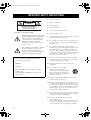
• Explanation of Graphical Symbols
1 Read these instructions.
2 Keep these instructions.
3 Heed all warnings.
4 Follow all instructions.
5 Do not use this apparatus near water.
6 Clean only with dry cloth.
7 Do not block any ventilation openings. Install in accordance
with the manufacturer’s instructions.
8 Do not install near any heat sources such as radiators, heat
registers, stoves, or other apparatus (including amplifiers)
that produce heat.
9 Do not defeat the safety purpose of the polarized or
grounding-type plug. A polarized plug has two blades with
one wider than the other. A grounding type plug has two
blades and a third grounding prong. The wide blade or the
third prong are provided for your safety. If the provided plug
does not fit into your outlet, consult an electrician for
replacement of the obsolete outlet.
10 Protect the power cord from being walked on or pinched
particularly at the plugs, convenience receptacles, and the
point where they exit from the apparatus.
11 Only use attachments/accessories specified by the
manufacturer.
12 Use only with the cart, stand, tripod,
bracket, or table specified by the
manufacturer, or sold with the apparatus.
When a cart is used, use caution when
moving the cart/apparatus combination to
avoid injury from tip-over.
13 Unplug this apparatus during lightning storms or when
unused for a long periods of time.
14 Refer all servicing to qualified service personnel. Servicing
is required when the apparatus has been damaged in any
way, such as power-supply cord or plug is damaged, liquid
has been spilled or objects have fallen into the apparatus, the
apparatus has been exposed to rain or moisture, does not
operate normally, or has been dropped.
15 Be sure to allow spaces of at least 10 cm above, behind and
on both sides of DVR-C310, and at least 1m above, 30cm
behind and on both sides of NX-SW300.
16 Do not place the following objects on this unit:
A vessel with water in it.
If the vessel falls by vibrations and water spills, it may cause
damage to the unit, and/or you may get an electric shock.
Apparatus shall not be exposed to dripping or splashing.
IMPORTANT SAFETY INSTRUCTIONS
IMPORTANT
Please record the serial number of this DVD
receiver in the space below.
MODEL:
Serial No.:
The serial number is located on the rear of this
DVD receiver.
Retain this Owner’s Manual in a safe place for
future reference.
CAUTION
RISK OF ELECTRIC SHOCK
DO NOT OPEN
CAUTION: TO REDUCE THE RISK OF
ELECTRIC SHOCK, DO NOT REMOVE
COVER (OR BACK). NO USER-SERVICEABLE
PARTS INSIDE. REFER SERVICING TO
QUALIFIED SERVICE PERSONNEL.
The lightning flash with arrowhead symbol,
within an equilateral triangle, is intended to
alert you to the presence of uninsulated
“dangerous voltage” within the product’s
enclosure that may be of sufficient
magnitude to constitute a risk of electric
shock to persons.
The exclamation point within an equilateral
triangle is intended to alert you to the
presence of important operating and
maintenance (servicing) instructions in the
literature accompanying the appliance.
01EN_DVX-C310_UC.book Page i Monday, July 10, 2006 11:22 AM

IMPORTANT SAFETY INSTRUCTIONS
ii
FCC INFORMATION (for US customers)
1 IMPORTANT NOTICE: DO NOT MODIFY THIS UNIT!
This product, when installed as indicated in the instructions contained in this manual, meets FCC requirements.
Modifications not expressly approved by Yamaha may void your authority, granted by the FCC, to use the product.
2 IMPORTANT: When connecting this product to accessories and/or another product use only high quality shielded cables.
Cable/s supplied with this product MUST be used. Follow all installation instructions. Failure to follow instructions could
void your FCC authorization to use this product in the USA.
3 NOTE: This product has been tested and found to comply with the requirements listed in FCC Regulations, Part 15 for Class
“B” digital devices.
Compliance with these requirements provides a reasonable level of assurance that your use of this product in a residential
environment will not result in harmful interference with other electronic devices. This equipment generates/uses radio
frequencies and, if not installed and used according to the instructions found in the users manual, may cause interference
harmful to the operation of other electronic devices. Compliance with FCC regulations does not guarantee that interference
will not occur in all installations. If this product is found to be the source of interference, which can be determined by turning
the product “OFF” and “ON”, please try to eliminate the problem by using one of the following measures:
Relocate either this product or the device that is being affected by the interference.
Utilize power outlets that are on different branch (circuit breaker or fuse) circuits or install AC line filter/s.
In the case of radio or TV interference, relocate/reorient the antenna. If the antenna lead-in is 300 ohm ribbon lead, change
the lead-in to coaxial type cable.
If these corrective measures do not produce satisfactory results, please contact the local retailer authorized to distribute this
type of product. If you can not locate the appropriate retailer, please contact Yamaha Electronics Corp., 6660 Orangethorpe
Ave. Buena Park, CA90622.
The above statements apply ONLY to those products distributed by Yamaha Corporation of America or its subsidiaries.
■ We Want You Listening For A Lifetime
YAMAHA and the Electronic Industries Association’s Consumer Electronics Group want you to get the most out
of your equipment by playing it at a safe level. One that lets the sound come through loud and clear without
annoying blaring or distortion - and, most importantly, without affecting your sensitive hearing.
Since hearing damage from loud sounds is often undetectable until it is too late, YAMAHA and the
Electronic Industries Association’s Consumer Electronics Group recommend you to avoid prolonged
exposure from excessive volume levels.
LASER SAFETY
This unit employs a laser. Due to possible eye injury, only
a qualified service person should remove the cover or
attempt to service this device.
DANGER
This unit emits visible laser radiation when open. Avoid direct
eye exposure to beam. When this unit is plugged into a wall
outlet, do not place your eyes close to the opening of the disc
tray and other openings or look inside.
SÉCURITÉ LASER
L'appareil utilise un laser. En raison des risques de blessure
des yeux, le retrait du couvercle ou les réparations de
l'appareil devront être confiés exclusivement à un
technicien d'entretien qualifié.
DANGER
Risque d'exposition au laser en cas d'ouverture. Eviter
toute exposition au faisceau. Lorsque cet appareil est
branché à la prise de courant, ne pas approcher les yeux de
l'ouverture du plateau changeur et des autres ouvertures
pour regarder à l'intérieur.
01EN_DVX-C310_UC.book Page ii Monday, July 10, 2006 11:22 AM

iii
1 To assure the finest performance, please read this manual
carefully. Keep it in a safe place for future reference.
2 Install this sound system in a well ventilated, cool, dry, clean
place with at least 10 cm on the top, 10 cm on the left and
right, and 10 cm at the back of DVR-C310 and at least 1 m
above, 30 cm behind and on both sides of NX-SW300 for
adequate ventilation. — away from direct sunlight, heat
sources, vibration, dust, moisture, and/or cold.
3 Locate this unit away from other electrical appliances,
motors, or transformers to avoid humming sounds.
4 Do not expose this unit to sudden temperature changes from
cold to hot, nor locate this unit in an environment with high
humidity (i.e., a room with a humidifier) to prevent
condensation inside this unit, which may cause an electrical
shock, fire, damage to this unit, and/or personal injury.
5 Avoid installing this unit in a location where foreign objects
may fall onto this unit or where this unit may be exposed to
liquid dripping or splashing. On the top of this unit, do not
place:
–Other components, as they may cause damage and/or
discoloration on the surface of this unit.
–Burning objects (i.e., candles), as they may cause fire,
damage to this unit, and/or personal injury.
–Containers with liquid in them, as they may fall, spilling
the liquid and causing an electrical shock to the user and/or
damage to this unit.
6 Do not cover this unit with a newspaper, tablecloth, curtain,
etc. in order not to obstruct heat radiation. If the temperature
inside this unit rises, it may cause fire, damage to this unit,
and/or personal injury.
7 Do not plug in this unit to a wall outlet until all connections
are complete.
8 Do not operate this unit upside-down. It may overheat,
possibly causing damage.
9 Do not use excessive force on switches, knobs and/or cords.
10 When disconnecting the power cord from the wall outlet,
grasp the plug; do not pull the cord.
11 Do not clean this unit with chemical solvents; this might
damage the finish. Use a clean, dry cloth.
12 Use only the voltage specified on this unit. Using this unit
with a higher voltage than specified is dangerous and may
cause fire, damage to this unit, and/or personal injury.
YAMAHA will not be held responsible for any damage
resulting from use of this unit with a voltage other than as
specified.
13 To prevent damage by lightning, keep the power cord out
and outdoor antennas disconnected from a wall outlet or the
unit during a lightning storm.
14 Do not attempt to modify or fix this unit. Contact qualified
YAMAHA service personnel when any service is needed.
The cabinet should never be opened for any reason.
15 When not planning to use this unit for long periods of time
(i.e., vacation), disconnect the AC power plug from the wall
outlet.
16 Be sure to read the “TROUBLESHOOTING” section on
common operating errors before concluding that this unit is
faulty.
17 Before moving this unit, press STANDBY/ON to set the
unit in standby mode, then disconnect the AC power plug
from the wall outlet.
18 Condensation will form when the surrounding temperature
changes suddenly. Disconnect the power cable from the
outlet, then leave the unit alone.
19 When using the unit for a long time, the unit may become
warm. Turn the power off, then leave the unit alone for
cooling.
20 Install this unit near the AC outlet and where the AC power
plug can be reached easily.
Be sure to place this unit on the level surface.
If you do not place this unit on the level surface,
PLAYXCHANGE will not function correctly, and may damage
the disc(s) and/or this unit itself.
CAUTION: READ THIS BEFORE OPERATING YOUR UNIT.
FOR CANADIAN CUSTOMERS
To prevent electric shock, match wide blade of plug to
wide slot and fully insert.
This Class B digital apparatus complies with Canadian
ICES-003.
This unit is not disconnected from the AC power
source as long as it is connected to the wall outlet, even
if this unit itself is turned off. This state is called the
standby mode. In this state, this unit is designed to
consume a very small quantity of power.
Laser component in this product is capable of emitting
radiation exceeding the limit for Class 1.
WARNING
TO REDUCE THE RISK OF FIRE OR ELECTRIC
SHOCK, DO NOT EXPOSE THIS UNIT TO RAIN
OR MOISTURE.
CAUTION
Danger of explosion if battery is incorrectly replaced.
Replace only with the same or equivalent type.
LASER
Type Semiconductor laser GaAlAs
Wave length 650 nm (DVD)
784 nm (VCD/CD)
Output Power 7 mW (DVD/VCD/CD)
Beam divergence 60 degrees
CAUTION
Use of controls or adjustments or performance of
procedures other than those specified herein may result
in hazardous radiation exposure.
01EN_DVX-C310_UC.book Page iii Monday, July 10, 2006 11:22 AM

1 En
1
2
3
4
5
6
English
INTRODUCTION .........................................2
Main unit ......................................................... 3
Supplied accessories ........................................ 3
FUNCTIONAL OVERVIEW .........................4
Front panel (DVR-C310) ................................ 4
Rear panel (DVR-C310) ................................. 5
Remote control (For DVR-C310) ................... 6
SPEAKER SETUP .......................................8
Roles and layout of the speakers ..................... 8
Placing the speakers ........................................ 9
Speaker connections ...................................... 10
Connecting the speaker cables ...................... 11
Connecting the subwoofer ............................. 11
Connecting the DVD receiver and
the subwoofer ............................................ 11
CONNECTION ...........................................12
Connecting a TV ........................................... 12
Connecting an HDMI component ................. 13
Connecting a VCR ........................................ 14
Connecting a YAMAHA
iPod universal dock ................................... 15
Connecting a digital audio component .......... 16
Connecting a portable audio player ............... 16
Connecting the FM/AM antennas ................. 17
GETTING STARTED .................................18
Inserting batteries into the remote control .... 18
Using the remote control ............................... 18
Turning on the power .................................... 19
Setting a TV type and display ....................... 19
Setting language preferences ......................... 20
DISC OPERATION ....................................21
Basic playback .............................................. 21
General operation .......................................... 21
Selecting various repeat/shuffle functions .... 22
Operations for video playback
(DVD/VCD/SVCD) .................................. 22
Special DVD features .................................... 24
Special VCD & SVCD features .................... 24
Playing MP3/JPEG/DivX® WMA discs ...... 25
Playing Super Audio CDs ............................. 25
DVD-Audio Features .................................... 26
Playing JPEG/Kodak picture CDs ................ 26
iPod® OPERATION ................................. 27
Controlling iPod using the OSD ....................27
DVD SETUP MENU OPTIONS ................. 28
Menu overview ..............................................28
Using the OSD menu .....................................29
General setup .................................................30
Audio setup ....................................................32
Video setup ....................................................34
Preference setup .............................................36
FM/AM TUNING ........................................ 39
Tuning stations ..............................................39
Presetting stations ..........................................39
XM® SATELLITE RADIO TUNING .......... 41
Activating XM Satellite Radio ......................43
Basic XM Satellite Radio operations ............ 43
Selecting the XM Satellite Radio
search mode ...............................................44
Setting the XM Satellite Radio
preset channels ...........................................45
Displaying the XM Satellite Radio
information ................................................45
SOUND CONTROLS ................................ 46
Selecting surround sound ..............................46
Selecting digital sound effects .......................46
Adjusting the treble/bass level .......................46
Adjusting the volume ....................................46
Muting the sound ...........................................46
REMOTE CONTROL FEATURES ............ 47
Setting remote control codes .........................47
Dimming the display screen ..........................48
Setting the sleep timer ...................................48
TROUBLESHOOTING .............................. 49
GLOSSARY .............................................. 52
SPECIFICATIONS .................................... 54
CONTENTS
1. INTRODUCTION
2. PREPARATION
3. BASIC OPERATION
4. TUNING OPERATION
5. ADVANCED OPERATION
6. ADDITIONAL INFORMATION
01EN_DVX-C310_UC.book Page 1 Monday, July 10, 2006 11:22 AM

INTRODUCTION
2 En
Thank you for purchasing this unit. This Owner’s Manual
explains the basic operation of this unit. This manual is
printed prior to production. Design and specifications are
subject to change in part as a result of improvements, etc.
In case of differences between the manual and the product,
the product has priority.
Notes about discs
–
This DVD receiver is designed for use with the following discs:
Super Audio CD (SA-CD), DVD-Video, Video CD, Super
Video CD, Audio CD, CD-R, CD-RW, DVD-Audio, DVD+RW,
DVD+R, DVD-R, DVD-RW and DVD-RW (VR format).
This DVD receiver can play:
– MP3 and picture (Kodak, JPEG) files recorded on CD-R(W)
– JPEG/ISO 9660 format (except Progressive JPEG)
• Up to a resolution of 3072 x 2048
• File name extensions (.jpg) must be used for this DVD
receiver to recognize JPEG files
– Maximum 30 character display
–DivX
®
disc on CD-R[W]/DVD+R[W]/DVD-R[W]
– The multiple sessions of CD-R/RW can be played.
– Only the single session of DVD+R/RW and DVD-R/RW
can be played.
– CD-R, CD-RW and DVD-RW (VR format) cannot be
played unless finalized.
– Some discs cannot be played depending on the recording
conditions, such as the PC environment and application
software. The characteristics and condition of some discs;
materials, scratches, curvature, etc., may result in
playback failure.
– Be sure to use only CD-R and CD-RW discs made by
reliable manufacturers.
– Do not use any non-standard shaped discs (heart-shaped, etc.).
– Do not use discs with tape, seals, or paste on their surface.
Doing so may damage this DVD receiver.
– Do not use discs affixed with labels printed by a
commercially available label printer.
Cleaning discs
– When a disc becomes dirty, clean it with a cleaning cloth.
Wipe the disc from the center out. Do not wipe in a circler
motion.
– Do not use solvents such as benzine, thinner,
commercially available cleaners, or antistatic spray
intended for analog records.
Disc care
– Write only on the printed side of a CD-R/CD-RW and
only with a soft felt-tipped pen.
– Handle the disc by its edge; do not touch the surface.
Region codes
DVD discs must be labeled ALL regions or
Region 1 (U.S.A. and Canada models) in order
to play on this DVD receiver. You cannot play
discs labeled for other regions.
Features
Active Servo Processing Subwoofer System with built-in power
amplifier.
This subwoofer system (NX-SW300) employes Advanced
YAMAHA Active Servo Technology which YAMAHA has
developed for reproducing higher quality super-bass sound. This
super-bass sound adds a more realistic, theater-in-the-home effect
to your stereo system.
PLAYXCHANGE
Capable of changing discs without interrupting current disc
playback.
Pressing PLAYXCHANGE on the front panel to open the disc
tray and reload or unload discs during playback.
Patent information
Manufactured under license from Dolby Laboratories. “Dolby”,
“Pro Logic”, “MLP Lossless” and the double-D symbol are
trademarks of Dolby Laboratories.
“DTS” and “DTS Digital Surround” are registered trademarks of
Digital Theater Systems, Inc.
“DivX”, “DivX Certified”, and associated logos are trademarks of
DivXNetworks, Inc. and are used under license.
The XM name and related logos are registered trademarks of XM
Satellite Radio Inc.
iPod®
“iPod” is a trademark of Apple Computer, Inc., registered in the
U.S. and other countries.
INTRODUCTION
Notes
This product incorporates copyright protection technology that is
protected by method claims of certain U.S. patents and other
intellectual property rights owned by Macrovision Corporation and
other rights owners. Use of this copyright protection technology
must be authorized by Macrovision Corporation, and is intended
for home and other limited viewing uses only unless otherwise
authorized by Macrovision Corporation. Reverse engineering or
disassembly is prohibited.
ALL
1
01EN_DVX-C310_UC.book Page 2 Monday, July 10, 2006 11:22 AM

3 En
INTRODUCTION
English
INTRODUCTION
1
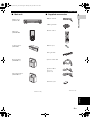
■ Main unit ■ Supplied accessories
DVD receiver
(DVR-C310)
Subwoofer
(NX-SW300)
Center speaker*
(NX-C300)
Front speakers*
(NX-F300 x 2)
Surround speakers*
(NX-S300 x 2)
INPUT
VOLUME
NATURAL SOUND HOME THEATER SYSTEM
1
23
4
5
PORTABLE
DISC
DVR-C310
PLAY
X
CHANGE
AUDIO/VIDEO
*DVX-C310 only
POWER
DISPLAY
SET UP
MENU
SRCH
DIMMER SLEEP
SCAN
A - B SHUFFLEREPEATPROG
ON SCREEN
SUBTITLE
PRESET
AUDIO ANGLE
EFFECT SURR
ZOOM
VOLTV CHTV VOL
TV AUX TUNER DVD/CD
CH
+
CATCAT
ENTER
CH
TOP MENU/RETURN
PAGE
POWER
+
XM
TV
OK
DISC
SKIP
TRE
BASS
MUTE
TV
INPUT
DOCK
System control cable
FM wire antenna
Video pin cable
Remote control
AM loop antenna
Speaker cables*
(5 m x 3)
(15 m x 2)
Batteries (x 2)
Fasteners (x 2)*
*DVX-C310 only
01EN_DVX-C310_UC.book Page 3 Monday, July 10, 2006 11:22 AM

FUNCTIONAL OVERVIEW
4 En
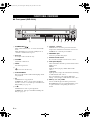
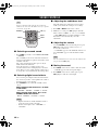
■ Front panel (DVR-C310)
1 STANDBY/ON ( )
Turns on this DVD receiver, or sets it to the standby
mode.
While this DVD receiver is in the standby mode, it
consumes a small amount of power.
2 Disc tray
Loads up to 5 discs in the disc tray.
3 VOLUME
Adjusts the volume level.
4 INPUT
Selects the input source.
5
Opens and closes the disc tray.
6 PLAYXCHANGE
Reloads or unloads discs without interrupting current
disc playback.
7 s
DVD/CD mode: stops playback.
TUNER mode: deletes a preset station if held more
than two seconds, or cancels the preset installation in
Plug and Play (see page 39).
8 h/e
DVD/CD mode: starts or pauses playback.
TUNER mode: starts preset installation in Plug and
Play (see page 39).
9 b/a, w/f
DVD/CD mode: selects the previous/next track or
chapter. Press and hold to fast forward or fast reverse.
TUNER mode: selects the preset number.
0 PORTABLE jack
Connects a portable audio player.
A Remote control sensor
Receives infrared signal from the remote control.
B Front panel display
Shows information about the operational status of this
DVD receiver.
MULTI
Lights up when you play a multi-channel audio
source.
DOWNMIX
Lights up when you play discs that allow down mixing
of multi-channel audio sources.
It does not light up for discs that prohibit down
mixing, even if you play a multi-channel audio source.
C DISC (1, 2, 3, 4, 5) / LEDs
Selects and directly plays back the preferred disc.
Each LED lights up in green when this DVD receiver
recognizes that the corresponding disc has been
loaded.
FUNCTIONAL OVERVIEW
INPUT
VOLUME
NATURAL SOUND HOME THEATER SYSTEM
1
23
4
5
PORTABLE
DISC
DVR-C310
PLAY
X
CHANGE
AUDIO/VIDEO
1
CBA0876
234
59
01EN_DVX-C310_UC.book Page 4 Monday, July 10, 2006 11:22 AM

5 En
FUNCTIONAL OVERVIEW
English
INTRODUCTION
1
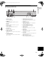
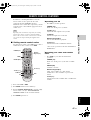
■ Rear panel (DVR-C310)
1 FM ANT terminal
Connect the FM antenna.
2 HDMI jack
Connect to an HDMI compatible component
(see page 13).
3 XM jack
Connect an XM Passport System (see page 41).
4 DOCK terminal
Connect a YAMAHA iPod universal dock
(see page 15).
5 AC power cord
Connect to a standard AC outlet.
6 VIDEO output jack
Connect to the video (composite) jack of your TV (see
page 12).
7 S-VIDEO output jack
Connect to the S-video jack of your TV or VCR (see
page 12, and 14).
8 COMPONENT VIDEO OUT jacks
Connect to the Y P
B/CB PR/CR jacks of your TV
(see page 12).
9 COAXIAL input jack
Connect to the digital out jack on a digital audio
component (see page 16).
0 SYSTEM CONNECTOR terminal
Connect to the subwoofer (see page 11).
A LINE OUT jacks
Connect to the audio input jacks of your VCR
(see page 14).
B AUX IN jacks
Connect to the audio output jacks on your VCR or
cassette deck (see page 14).
C TV IN jacks
Connect to the corresponding audio output jacks of
your TV (see page 12).
D GND and AM ANT terminals
Connect the AM loop antenna (see page 17).
TV IN
ANTENNA
AUX IN
LINE OUT
TO NX-SW300
SYSTEM
CONNECTOR
DOCK
VIDEO
S VIDEO
COMPONENT
COAXIAL
DIGITAL IN
VIDEO OUT (DVD ONLY)
PCM/DTS
q
DIGITAL
YP
R
P
B
XMHDMI
GND
AM
FM
75
UNBAL.
1
CBA 98 76
234 5
0
D
01EN_DVX-C310_UC.book Page 5 Monday, July 10, 2006 11:22 AM

6 En
FUNCTIONAL OVERVIEW
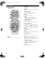
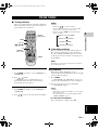
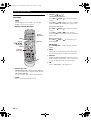
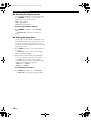
■ Remote control
(For DVR-C310)
For details on how to use the remote control, see page 18.
1 POWER (TV)
Turns on the TV, or sets it to the standby mode.
2 DIMMER
Selects different levels of brightness for the display
panel.
3 Numeric keypad (0 – 9)
Enters a track/title number of the disc.
Enters a number of a preset radio station.
4 REPEAT
Selects various repeat modes.
5 PROG
DVD/CD mode: starts programming.
TUNER mode: starts automatic/manual preset
programming if held for more than two seconds.
6 TOP MENU/RETURN
Returns to the previous menu.
Displays the top-level disc menu (if available).
7 Cursors ( // / )
DVD/CD mode: Use to select OSD menu items.
TUNER mode: press / to tune into a station or
press / to starts automatic tuning. When this
DVD receiver is in the XM Satellite Radio mode, see
page 42.
ENTER (OK)
Confirms a selection.
8 MENU
Accesses the menu of a disc. During playback, returns
to the main menu.
For VCD version 2.0 only:
Switches PBC (playback control) on or off.
9 s
DVD/CD mode: stops playback. Holding down the
button opens and closes the disc tray.
TUNER mode: deletes a preset station if held more
than two seconds, or cancels the preset installation in
Plug and Play (see page 39).
0 u PRESET d (b/a)
DVD/CD mode: selects the previous/next track or
chapter. Press and hold to fast forward or fast reverse.
TUNER mode: selects the preset number.
A SUBTITLE
Selects a subtitle language.
Note
POWER
DISPLAY
SET UP
MENU
SRCH
DIMMER SLEEP
SCAN
A - B SHUFFLEREPEATPROG
ON SCREEN
SUBTITLE
PRESET
AUDIO ANGLE
EFFECT SURR
ZOOM
VOLTV CHTV VOL
TV AUX TUNER DVD/CD
CH
+
CATCAT
ENTER
CH
TOP MENU/RETURN
PAG E
POWER
+
XM
TV
OK
DISC
SKIP
TRE
BASS
MUTE
TV
INPUT
DOCK
7
8
9
0
A
B
C
D
E
F
G
1
2
3
6
R
S
t
U
V
W
X
H
I
L
N
M
J
K
O
P
Q
4
5
01EN_DVX-C310_UC.book Page 6 Monday, July 10, 2006 11:22 AM

7 En
FUNCTIONAL OVERVIEW
English
INTRODUCTION
1
B AUDIO
Selects an audio language (DVD) or an audio channel
(VCD).
C TV CH (+ / –)
Switches the TV channel.
D TV VOL (+ / –)
Adjusts the TV volume.
E TV INPUT
Switches the TV input.
F EFFECT
Selects a sound effect.
G Input selection buttons
Select the input source.
TV: switches to TV input source.
AUX: switches to AUX ANALOG, AUX DIGITAL or
AUX FRONT input source.
TUNER: switches to TUNER/FM, TUNER/AM or
XM RADIO input source.
DVD/CD: switches to DVD/CD or iPod input source.
H POWER ( )
Turns on this DVD receiver, or sets it to the standby
mode.
While this DVD receiver is in the standby mode, it
consumes a small amount of power.
I SLEEP
Sets the sleep timer.
J SCAN
Scans each track/chapter on the disc.
K PAGE
Turns the pages of DVD-Audio still pictures.
L REPEAT A-B
Repeats a specific section on a disc.
M SHUFFLE
Plays tracks in random order.
N ON SCREEN/DISPLAY
Accesses or exits from the OSD (on screen display)
menu of this DVD receiver.
O SET UP
Accesses or exits from the setup menu of this DVD
receiver.
P h
DVD/CD mode: starts playback.
TUNER mode: starts preset installation in Plug and
Play (see page 39).
Q e
DVD/CD mode: pauses playback.
R DISC SKIP
Selects another disc.
S ZOOM
Enlarges the video image.
T ANGLE
Selects a DVD disc camera angle (if available).
U TRE/BASS
Selects the TREBLE (high tone) or BASS (low tone)
sound mode.
Use the VOLUME control to change the tone level.
V VOL (+ / –)
Adjusts the volume level.
W MUTE
Mutes the sound. Press again to restore the audio
output to the previous volume level.
X SURR
Switches to multi-channel surround mode or stereo
mode.
01EN_DVX-C310_UC.book Page 7 Monday, July 10, 2006 11:22 AM

SPEAKER SETUP
8 En
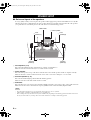
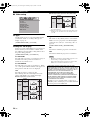
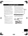
■ Roles and layout of the speakers
To enjoy quality sounds you need to place the speakers in their appropriate positions and install them correctly.The
following shows the recommended layout of the speakers. For the best possible surround sound, all of the speakers
(except the subwoofer) should be placed at the same distance from the listening position.
1 Front Speakers (L, R)
Place the front left/right speakers on both sides of your TV at equal distances.
Main roles: Produces front channel (stereo) sounds and effect sounds.
2 Center Speaker
Place the center speaker on top of the TV or inside the TV rack so that the speaker and TV are aligned vertically.
Main role: Produces sounds oriented toward the center of the screen such as dialogues or vocal sounds.
3 Surround Speakers (L, R)
Place the surround left/right speakers behind the listening position.
Main roles: Produces surround sounds and effect sounds.
4 Subwoofer
Place the subwoofer near a front speaker and turn it slightly toward the center of the room to reduce wall reflections.
Main roles: Produces bass sounds and low frequency (LFE) sounds contained in Dolby Digital or DTS.
– To avoid magnetic interference, do not position the front speakers too close to your TV.
– Allow adequate ventilation around the DVD receiver and subwoofer.
– Bass sounds produced by the subwoofer may be heard differently depending on the listening position and subwoofer location.
To enjoy desired sounds, try to change the location of the subwoofer according to the listening position.
SPEAKER SETUP
1
1
2
3
4
3
DVD receiver
Center speaker
Front
speaker (R)
Surround
speaker (L)
Subwoofer
Surround
speaker (R)
Front
speaker (L)
Notes
01EN_DVX-C310_UC.book Page 8 Monday, July 10, 2006 11:22 AM

SPEAKER SETUP
9 En
English
PREPARATION
2
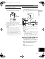
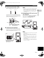
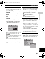
■ Placing the speakers
Placing the center speaker (NX-C300)
When placing the center speaker on the top of the TV,
use the supplied fasteners to secure the speaker.
1 Peel off the seals on one side of the fasteners and
attach them to the bottom of the center speaker.
2 Peel off the seals on the other side of the fasteners and
attach them to the top of the TV.
– Do not place the speaker on the TV if the top of the TV is
uneven or narrower than the bottom surface of the
speaker. Doing so may cause the speaker to fall. In this
case, place the speaker inside a TV rack or on a level
floor.
– Before attaching the fasteners to the TV, clean the surface
with a dry cloth. A dirty or wet surface may weaken the
adhesive force and cause the speaker to fall.
– Do not touch the bonding surfaces of the fasteners after
peeling off the seals. Doing so may weaken the adhesive
force and cause the speaker to fall.
Attaching to a wall
You can attach the speakers to a wall using
commercially available screws (Diameter: 3.5 to 4 mm
(1/8” to 5/32”), Length: 25 mm (1”) or more). Each
speaker requires two screws.
1 Install two screws in the wall where you want to place
the speaker.
2 Hang the speaker on the screws using the holes in the
rear of the speaker.
– To attach a speaker to a wall using screws, the wall must
be firm. Do not attach a speaker to a wall that is made of
weak materials such as plaster or veneered woods. Doing
so may cause the speaker to fall.
– After attaching each speaker, check that the speaker is
fixed securely. YAMAHA will bear no responsibility for
any accidents caused by improper installations.
Hanging on a wall (NX-F300, NX-S300)
You can hang the speakers on a wall using a
commercially available bracket and screws (Diameter:
6 mm). Attach a bracket firmly to the rear of the
speakers using screws. Then mount a screw on the
wall where the speaker is to be hung and hook the
speaker securely onto the mounted screws.
Do not use screw threads measured in inches for this
installation. Use metric screw threads only.
Notes
Fastener
Peel off
the seal
Notes
Note
+
–
+
–
Screws
(3.5 (1/8”) to 4 (5/32”)
mm dia., commercially
available)
20 mm (25/32”)
or more
79 mm
(2-3/4”)
5 mm
(1/5”)
151 mm
(5-15/16”)
01EN_DVX-C310_UC.book Page 9 Monday, July 10, 2006 11:22 AM

SPEAKER SETUP
10 En
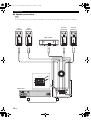
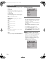
■ Speaker connections
Do not connect the power cord of the subwoofer and DVD receiver into an AC outlet until all cable connections are completed.
Note
+
–
+
–
+
–
+
–
+
–
TV IN
ANTENNA
AUX I N
LINE OUT TO NX-SW300
SYSTEM
CONNECTOR
DOCK
VIDEO
S VIDEO
COMPONENT
COAXIAL
DIGITAL IN VIDEO OUT (DVD ONLY)
PCM/DTS
q
DIGITAL
YP
R
P
B
XMHDMI
GND
AM
FM
75Ω
UNBAL.
L
R
FRONT
CENTE R
SURROUND
FRONT
CENTER
SURROUND
SPEAKERS
Subwoofer
DVD receiver
Front
speaker (R)
Front
speaker (L)
Center speaker
Surround
speaker (R)
Surround
speaker (L)
01EN_DVX-C310_UC.book Page 10 Monday, July 10, 2006 11:22 AM

SPEAKER SETUP
11 En
English
PREPARATION
2
■ Connecting the speaker cables
Be sure to twist the cable core firmly in a clockwise
direction. Twisting loosely may cause a short.
Connect the speaker cable with the white line to the
plus (Red (+)) connector on the front/center/surround
speakers and connect the speaker cable with the black
band to the minus (Black (–)) connector.
■ Connecting the subwoofer
Connect the speaker cable with the white line to the
plus (Red (+)) connector on the front/center/surround
speakers and connect the speaker cable with the black
band to the minus (Black (–)) connector.
– Do not use excessive force when inserting the cable plug.
Doing so may damage the cable or speaker terminals.
– When connecting the speakers, fix the speaker cables in
place so that cables do not loosen. If your foot or hand
accidentally gets caught on a loose speaker cable, the
speaker may fall.
■ Connecting the DVD receiver and
the subwoofer
Connect the subwoofer to DVD receiver using the
system control cable. Attach one end to the subwoofer
and the other to the SYSTEM CONNECTOR
terminal at the rear of the DVD receiver.
– After inserting the system control cable, be sure to tighten
the cable screws.
– Ensure that the speaker cables are correctly connected.
Improper connections may damage the system due to a
short-circuit.
– When connecting the speakers, fix the speaker cables in
place so that cables do not loosen. If your foot or hand
accidentally gets caught on a loose speaker cable, the
speaker may fall.
– To prevent unwanted noise, do not place the subwoofer
too close to the DVD receiver, AC power adaptor, TV or
other sources of radiation.
Good
No Good
Lever
Black
band
Press the lever down, then
insert the cable into the hole
and release the lever.
FRONT
CENTER
SURROUND
SPEAKERS
Lift up the lever, then insert
the cable into the hole and
replace the lever.
Lever
Black
band
NX-SW300
Notes
Notes
TV IN
ANTENNA
AUX IN
LINE OUT TO NX-SW300
SYSTEM
CONNECTOR
DOCK
VIDEO
S VIDEO
COMPONENT
COAXIAL
DIGITAL IN VIDEO OUT (DVD ONLY)
PCM/DTS
q
DIGITAL
YPR
PB
XMHDMI
GND
AM
FM
75Ω
UNBAL.
L
R
SYSTEM
CONNECTOR
SYSTEM
CONNECTOR
NX-SW300
01EN_DVX-C310_UC.book Page 11 Monday, July 10, 2006 11:22 AM

CONNECTION
12 En
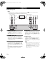
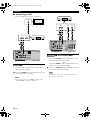
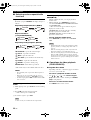
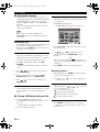
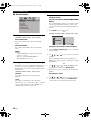
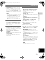
■ Connecting a TV
– You only need to make one audio connections from the following options (1 or 2) and one video connection from the
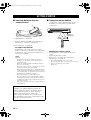
following options (1,2 or 3) depending on the capabilities of your TV.
– Do not connect the power cords until all cable connections are completed.
1 VIDEO output jack
Use the supplied video pin cable (yellow) to connect
the VIDEO jack of this DVD receiver to the video
input jack (or A/V In/Video In/Composite/Baseband
jack) of your TV.
2 S VIDEO output jack
S-video connections achieve a clearer picture than
composite video connections. Use a commercially
available S-video cable to connect the S VIDEO jack
of this DVD receiver to the S-video input jack (or Y/C
or S-VHS jack) of your TV.
3 COMPONENT VIDEO OUT jacks
Use commercially available component video cables
(red/blue/green) to connect the Y P
B PR jacks of this
DVD receiver to the corresponding component video
input jacks (or the Y Pb/Cb Pr/Cr/ YUV jacks) of your
TV.
Progressive scan video quality is only available when
using Y P
B PR in conjunction with a progressive scan
TV. To activate the progressive scan function see
page 34.
1 TV IN jacks
To output TV sound from the speakers connected to
this DVD receiver, use commercially available audio
cables (white/red) to connect the TV IN input jacks of
this DVD receiver to the corresponding audio output
jacks of your TV.
2 COAXIAL jack
To output TV sound from the speakers connected to
this DVD receiver, use a commercially available
coaxial cable to connect the COAXIAL input jack of
this DVD receiver to the corresponding coaxial output
jack of your TV.
– If you connect this DVD receiver to the analog audio and
digital audio at the same time, the digital audio signals
input at the COAXIAL jack take priority over the analog
audio signals input at the TV IN jacks.
– You can connect this DVD receiver to your TV using an
HDMI cable. For details, see “Connecting an HDMI
component” on page 13.
CONNECTION
Notes
TV IN
ANTENNA
AUX IN
LINE OUT TO NX-SW300
SYSTEM
CONNECTOR
DOCK
VIDEO
S VIDEO
COMPONENT
COAXIAL
DIGITAL IN VIDEO OUT (DVD ONLY)
PCM/DTS
q
DIGITAL
YPR
PB
XMHDMI
GND
AM
L
R
AUDIO
OUT
COAXIAL
OUT
Pr/Cr Pb/Cb Y
VIDEO
IN
S-VIDEO
IN
12312
R L
TV
Video connections
Audio connections
Notes
01EN_DVX-C310_UC.book Page 12 Monday, July 10, 2006 11:22 AM

CONNECTION
13 En
English
PREPARATION
2
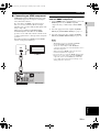
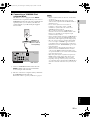
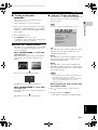
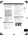
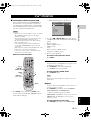
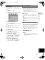
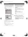
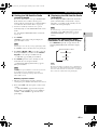
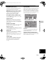
■ Connecting an HDMI component
HDMI (High-Definition Multimedia Interface) is the
first industry-supported, uncompressed, all-digital
A/V (audio/video) interface.
By connecting to an HDMI component (such as a
TV), you can enjoy standard, enhanced or high-
definition video as well as multi-channel digital audio
using a single cable.
When used in combination with HDCP (High-
bandwidth Digital Content Protection), HDMI
provides a secure audio/video interface that meets the
security requirements of content providers and system
operators.
For further information on HDMI, visit the HDMI
website at “http://www.hdmi.org/”.
Viewing and Listening to playback
from an HDMI component
1 Connect HDMI output jack of this DVD receiver to the
HDMI input jack of your HDMI compatible
component using a commercially available HDMI
cable.
2 Select the appropriate audio output from [HDMI
SETUP] in [AUDIO SETUP PAGE] (see page 33).
3 Select the appropriate video output from [HDMI
SETUP] in [VIDEO SETUP PAGE] (see page 35).
– This DVD receiver is not compatible with HDCP-
incompatible HDMI or DVI components.
– You need a commercially available HDMI/DVI
conversion cable when you connect this DVD receiver to
other DVI components.
– When connecting an HDMI component, refer to the
instruction manual for the component.
– Do not disconnect or connect the HDMI cable from this
DVD receiver or turn off the power of the HDMI/DVI
component connected to the HDMI jack of this DVD
receiver while data is being transferred. Doing so may
disrupt playback or cause noise.
TV IN
ANTENNA
AUX IN
LINE OUT TO NX-SW300
SYSTEM
CONNECTOR
DOCK
XMHDMI
GND
AM
L
R
HDMI
IN
TV
DVD receiver
Notes
01EN_DVX-C310_UC.book Page 13 Monday, July 10, 2006 11:22 AM

CONNECTION
14 En
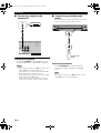
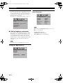
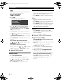
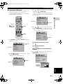
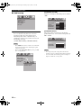
■ Connecting a VCR
Connect a VCR and enjoy video cassette tapes.
Viewing and listening to playback
from a VCR
1 Connect the video output jack of the VCR and the
video input jack of your TV.
2 Connect the AUX IN jacks of this DVD receiver to the
audio output jacks of your VCR.
Before starting operation, press AUX repeatedly to select
“AUX ANALOG” to activate the input source.
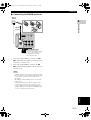
Using a VCR for recording DVD
playback
1 Connect the S VIDEO output of this DVD receiver to
the S-video input jack of your VCR.
OR
Connect the VIDEO output jack of this DVD receiver
and the video input jack of your VCR.
2 Connect the LINE OUT jacks of this DVD receiver to
the audio input jacks of your VCR.
Some DVDs are copy protected. You cannot record copy-
protected discs using a VCR.
Note
TV IN
ANTENNA
AUX IN
LINE OUT TO NX-SW300
SYSTEM
CONNECTOR
DOCK
XMHDMI
GND
AM
L
R
1
AUDIO
OUT
VIDEO
IN
VIDEO
OUT
RL
2
VCR
DVD receiver
TV
Note
L
R
TV IN
ANTENNA
AUX IN
LINE OUT
XMHDMI
GND
AM
VIDEO
S VIDEO
COMPONENT
COAXIAL
DIGITAL IN VIDEO OUT (DVD ONLY)
PCM/DTS
q
DIGITAL
YP
R
P
B
1
AUDIO
IN
VIDEO
IN
2
RL
S-VIDEO
OUT
VCR
DVD receiver
01EN_DVX-C310_UC.book Page 14 Monday, July 10, 2006 11:22 AM

CONNECTION
15 En
English
PREPARATION
2
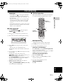
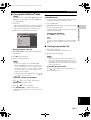
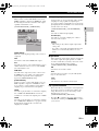
■ Connecting a YAMAHA iPod
universal dock
This DVD receiver is equipped with the DOCK
terminal on the rear panel that allows you to connect a
YAMAHA iPod universal dock (such as YDS-10 sold
separately) where you can station your iPod and
control playback of your iPod using the supplied
remote control.
1 Connect a YAMAHA iPod universal dock to the
DOCK terminal on the rear panel of this DVD
receiver using its dedicated cable.
2 Once the connection is complete, station your iPod in
the YAMAHA iPod universal dock.
For details on how to operate your iPod, see page 27.
– Only iPod (Click and Wheel), iPod nano, and iPod mini
are supported.
– You need a YAMAHA iPod universal dock and its
dedicated cable compatible with the DOCK terminal of
this DVD receiver.
– Do not connect any iPod accessories (such as
headphones, a wired remote control, or an FM
transmitter) to your iPod when it is stationed in a
YAMAHA iPod universal dock.
– Once your iPod is stationed in a YAMAHA iPod
universal dock connected to the DOCK terminal of this
DVD receiver, this DVD receiver begins the signal
transmission with your iPod.
– Unless your iPod is firmly stationed in a YAMAHA iPod
universal dock connected to the DOCK terminal of this
DVD receiver, audio signals may not be output properly.
– Once the connection between your iPod and this DVD
receiver is complete, “DOCKED” appears in the front
panel display. If the connection between your iPod and
this DVD receiver fails, “NOT DOCKED” appears in the
front panel display.
– Your iPod battery is automatically charged when your
iPod is stationed in a YAMAHA iPod universal dock
connected to the DOCK terminal of this DVD receiver
except when this DVD receiver is turned off, in DVD/CD
mode and in changer mode.
– Only analog audio signals of your iPod are input at the
DOCK terminal, and the analog audio signals can be
output at the analog LINE OUT jacks for recording.
– Depending on the type of iPod, you may need to insert
one of the iPod adapters supplied with a YAMAHA iPod
universal dock into the dock slot before you station your
iPod.
TV IN
ANTENNA
AUX IN
LINE OUT TO NX-SW300
SYSTEM
CONNECTOR
DOCK
XMHDMI
GND
AM
L
R
FM
75
UNBAL.
iPod
YAMAHA iPod
universal dock
(such as YDS-10
sold separately)
DVD receiver
Notes
01EN_DVX-C310_UC.book Page 15 Monday, July 10, 2006 11:22 AM

CONNECTION
16 En
■ Connecting a digital audio
component
Listening to playback
Connect the COAXIAL jack of this DVD receiver to
the digital output jack of a digital audio component.
– Before starting operation, press AUX repeatedly to select
“AUX DIGITAL” to activate the input source.
– You cannot hear or record the Super Audio-CD or MP3-
CD playback if you use a digital connection.
– For playback through a digital connection, set the digital
output of that player to PCM format.
– Always refer to the owner’s manual of the connected
component for complete connection and usage details.
■ Connecting a portable audio
player
Be sure to turn off the volume of this DVD receiver and the
connected component before making connections.
Listening to playback
Use the PORTABLE jack on the front panel to
connect your portable audio player to this DVD
receiver.
Before starting operation, press AUX repeatedly to select
“AUX FRONT” to activate the input source.
Notes
VIDEO
S VIDEO
COMPONENT
COAXIAL
DIGITAL IN VIDEO OUT (DVD ONLY)
PCM/DTS
q
DIGITAL
YP
R
P
B
COAXIAL
OUT
CD player, etc.
DVD receiver
Note
PLAY
X
CHANGE
INPUT
VOLUM E
AUDIO/VIDEO
1
23
4
5
PORTABLE
DISC
PORTABLE
Portable audio
player
01EN_DVX-C310_UC.book Page 16 Monday, July 10, 2006 11:22 AM
Page is loading ...
Page is loading ...
Page is loading ...
Page is loading ...
Page is loading ...
Page is loading ...
Page is loading ...
Page is loading ...
Page is loading ...
Page is loading ...
Page is loading ...
Page is loading ...
Page is loading ...
Page is loading ...
Page is loading ...
Page is loading ...
Page is loading ...
Page is loading ...
Page is loading ...
Page is loading ...
Page is loading ...
Page is loading ...
Page is loading ...
Page is loading ...
Page is loading ...
Page is loading ...
Page is loading ...
Page is loading ...
Page is loading ...
Page is loading ...
Page is loading ...
Page is loading ...
Page is loading ...
Page is loading ...
Page is loading ...
Page is loading ...
Page is loading ...
Page is loading ...
Page is loading ...
Page is loading ...
-
 1
1
-
 2
2
-
 3
3
-
 4
4
-
 5
5
-
 6
6
-
 7
7
-
 8
8
-
 9
9
-
 10
10
-
 11
11
-
 12
12
-
 13
13
-
 14
14
-
 15
15
-
 16
16
-
 17
17
-
 18
18
-
 19
19
-
 20
20
-
 21
21
-
 22
22
-
 23
23
-
 24
24
-
 25
25
-
 26
26
-
 27
27
-
 28
28
-
 29
29
-
 30
30
-
 31
31
-
 32
32
-
 33
33
-
 34
34
-
 35
35
-
 36
36
-
 37
37
-
 38
38
-
 39
39
-
 40
40
-
 41
41
-
 42
42
-
 43
43
-
 44
44
-
 45
45
-
 46
46
-
 47
47
-
 48
48
-
 49
49
-
 50
50
-
 51
51
-
 52
52
-
 53
53
-
 54
54
-
 55
55
-
 56
56
-
 57
57
-
 58
58
-
 59
59
-
 60
60


Ask a question and I''ll find the answer in the document
Finding information in a document is now easier with AI
Related papers
Other documents
-
Philips HTS3090/98 Quick start guide
-
-
-
Eltax Vision User manual
-
COBY electronic TF-DVD1256 User manual
-
Philips HTS3000/51 User manual
-
TEAC CR-H227I User manual
-
Audiovox DV7300 User manual
-
-
RCA RTS202 User manual