PLAN HOW YOU WILL INSTALL YOUR WATER HEATER
3. Fasten a length of garden hose to the water heater drain
valve. Place the other end of the hose at a suitable drain
point, lower than the drain valve (nearby floor drain, sink, tub,
or outside), open ,the drain valve and let all water drain from
the water heater. READ THE FOLLOWING WARNING.
WARNING
J WATER FROM THE DRAIN HOSE MAY BE VERY HOT. BE J
I
SURE NO ONE IS NEAR THE DRAIN HOSE OR THEY
I
COULD GET BURNED SEVERELY.
NOTE: For faster draining, open a hot water faucet, or the
temperature and pressure relief valve, so air can enter the
water heaterplumbing system.
4. DO STEP 1, if not already done. Then remove the water
heater junction box access cover.Disconnect electrical supply
wires to the water heater.
5. When all water has drained from the water heater, remove
the garden hose from the drain valve and close the valve.
6. Disconnect (or cut) the inlet and outlet water supply pipes
close to the water heater. Be careful not to damage the pipes
ifyou want to reuse them for installing your new water heater.
7. Remove and properly dispose of the old water heater.
CAUTION: Mineral buildup or sediment may have accumulat-
ed in your old water heater.This causes the water heater to be
much heavier than normal. The remaining water and residue, if
spilled out,could cause staining.
STEPS TO INSTALL YOUR WATER HEATER
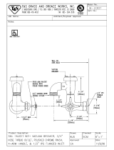
VACUUM RELIEF VALVE
• (FIG. 1, PAGE 5).
Your new waterheater is designed to give you many years of trouble
free service. To help safeguard your water heater investment, a
VACUUM RELIEF VALVEhas been included with the parts kit. It must
be installed according to the note below and the instructions on Page
5 to assure warranty coverage.
Certain conditions such as breakage in the main supply line, pump
failure on a well system or other plumbing system malfunctions may
cause atemporary pressure loss. The installation of the vacuum relief
valve on the cold water supply line to the water heater will allow air to
enter the tank and prevent damage in the event such conditions occur.
NOTE: The vacuum relief valve MUST be installed vertically at or
above the highest point of the tank. Do not install the shut-off valve
between the vacuum reliefvalve and the tank (see FIG. 1, Page 5).
NOTE:If your water pressure is over80 PSI, be sureto installa pressure
reducing valve (water pressure regulator) in the inlet
supply pipeto the water heater(seethe SafetyGuideson Page2).
COLD WATER SUPPLY TO WATER
• HEATER (FIG. 1, PAGE 5).
• Heat traps have been installed on your water heater to help
achieve the best operating efficiency. Heat traps help
prevent heat from flowing from the inlet and out[et
plumbing connections during periods when the heater is not heat-
ing water. To replace a plugged or damaged heat trap due to
scale build-up, be sure to follow the "CAUTIONS" on Page 4 and
illustrations on Pages5 and 13.
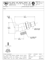
CAUTIONS: BE SURE TO INSTALL HEAT TRAPS AT THE CORRECT
WATER HEATER CONNECTION. OBSERVE FLOW ARROWS ON
THE HEAT TRAPS. IF INSTALLED WRONG, WATER FLOW
THROUGH THE WATER HEATER IS GREATLY REDUCED.
Use pipe joint compound or Teflon tape on the heat trap threads. The
last connection to the water heater must use the factory supplied
seal ring washers only. DO NOT use sealants with seal ring washers.
DONOTREMOVECOLOREDPLASTICiNSERTSFROMTHEHEATTRAPS.
DO NOT SWEAT SOLDER DIRECTLY TO THE HEAT TRAPS. DO
ALL SOLDERING FIRST. THEN CONNECT HEAT TRAPS TO THE
PIPES AND TO THE WATERHEATER.
FOLLOWALL INSTALLATIONINSTRUCTIONSINTHIS MANUAL.
• Thread the cold side heat trap into the 1" x 3/4" reducer bushing
using pipe joint compound or teflon tape.
• Loosely assemble the 1" x 3/4" reducer bushing with the cold
side heat trap attached to the INLET (COLD) hex union. Be sure
the seal dng is in place in the hex union. (Use factory supplied seal
ring washers only. DO NOT use sealants with seal ring washer.)
DO NOT TIGHTEN THE HEX UNION. Tightening of the hex
union will be done later, this is to help aid in measuring the
amount of pipe or tube that may need to be cut.
• Run a cold water supply line to the cold side heat trap using Sears
water heater installation kit (Page 3), threaded galvanized,
soldered copper or CPVC plastic pipe and fittings.
• Be sure to include a shut-off valve and fittings for the
vacuum relief valve as shown in FiG. 1, Page 5.
• Use pipe thread seal compound or teflon tape on all
outside threads. The last connection to the water heater
must use the factory supplied seal ring washers only, DO
NOT use sealants with seal ring washers,
• Read the following caution notes before tightening fittings,
soldering or cementing.
CAUTION: TO PREVENTHEATTRANSFERAND DAMAGETO THE
iNLET FITTINGAND HEATTRAR,DISCONNECT THE HEX UNION
NUTFROMTHEREDUCERBUSHING AND THE HEATTRAP FROM '
THE SWEATTO FEMALE PIPE ADAPTOR BEFORE SOLDERING.
ALWAYSTIGHTEN THE HEX UNION LAST, AFTER PLUMBING IS
iN PLACE, ALIGNED, SOLDERED, ETC. DO NOT A'I7"EMPTTO
TURN PIPE OR FITTINGS AFTER HEX UNIONS ARE TIGHT OR
YOUWILLDAMAGETHEWATERHEATERBEYONDREPAIR.
NOTE: If yourwater heater is installed using a check valve inthe water
line or a water meter wwith a check valve, contact the Sears Service
Center or localwater authoriity on how to control-this situation.
= HOT WATER PIPE FROM THE
WATER HEATER.
Install the hot side heat trap to the outlet (HOT) hex union nut. Be
sure a seat ring is in the hex union (USE FACTORY SUPPUED SEAL
RING WASHERS ONLY.DO NOT USESEALANTS WITH SEAL RING
WASHERS.)
Make all pipe to fitting connections the same way as you did in Step
2, observing the hex union and heat trap sweat to pipe adaptor fit-
ting, caution and tightening procedures listed on Page 4. Refer to the
instructions on Page'4, Step 2, and FIG.A, Page 13to replace a heat
trap.
• TEMPERATURE AND PRESSURE RELIEF
VALVE (See * Note on Page 2).
Your Survivor water heater was shipped with a temperature and
pressure relief valve factory installed. Do not operate the water heater
unless the temperature and pressure relief valve is in place and
working properly. A relief valve is essential for safety and to protect
the water heater.Too high of a temperature and/or pressure inside the
water heater could cause it to burst. The relief valve automatically
opens if temperature or pressure gets too high to relieve hot water
and/or pressure to the drain. READ AND COMPLY WITH THE
WARNING ON PAGE6.