Page is loading ...

Instruction Manual
245364-V
May 2002
http://www.processanalytic.com
Model 755A
Oxygen Analyzer

Emerson Process Management
Rosemount Analytical Inc.
Process Analytic Division
1201 N. Main St.
Orrville, OH 44667-0901
T (330) 682-9010
F (330) 684-4434
e-mail: [email protected]
http://www.processanalytic.com
ESSENTIAL INSTRUCTIONS
READ THIS PAGE BEFORE PROCEEDING!
Rosemount Analytical designs, manufactures and tests its products to meet many national and
international standards. Because these instruments are sophisticated technical products, you
MUST properly install, use, and maintain them to ensure they continue to operate within their
normal specifications. The following instructions MUST be adhered to and integrated into your
safety program when installing, using, and maintaining Rosemount Analytical products. Failure to
follow the proper instructions may cause any one of the following situations to occur: Loss of life;
personal injury; property damage; damage to this instrument; and warranty invalidation.
• Read all instructions prior to installing, operating, and servicing the product.
• If you do not understand any of the instructions, contact your Rosemount Analytical representative
for clarification.
• Follow all warnings, cautions, and instructions marked on and supplied with the product.
• Inform and educate your personnel in the proper installation, operation, and maintenance of
the product.
• Install your equipment as specified in the Installation Instructions of the appropriate
Instruction Manual and per applicable local and national codes. Connect all products to the
proper electrical and pressure sources.
• To ensure proper performance, use qualified personnel to install, operate, update, program, and
maintain the product.
• When replacement parts are required, ensure that qualified people use replacement parts specified by
Rosemount. Unauthorized parts and procedures can affect the product’s performance, place the safe
operation of your process at risk, and VOID YOUR WARRANTY. Look-alike substitutions may result
in fire, electrical hazards, or improper operation.
• Ensure that all equipment doors are closed and protective covers are in place, except when
maintenance is being performed by qualified persons, to prevent electrical shock and personal
injury.
The information contained in this document is subject to change without notice.
Teflon is a registered trademark of E.I. duPont de Nemours and Co., Inc.
SNOOP is a registered trademark of NUPRO Co.

Instruction Manual
245364-V
May 2002
Rosemount Analytical Inc. A Division of Emerson Process Management Contents i
Model 755A
TABLE OF CONTENTS
PREFACE...........................................................................................................................................P-1
Definitions ...........................................................................................................................................P-1
Intended Use Statement.....................................................................................................................P-2
Safety Summary .................................................................................................................................P-2
General Precautions For Handling And Storing High Pressure Gas Cylinders .................................P-4
Documentation....................................................................................................................................P-5
Compliances .......................................................................................................................................P-5
1-0 DESCRIPTION AND SPECIFICATIONS..............................................................................1-1
1-1 Overview................................................................................................................................1-1
1-2 Oxygen Range on Front Panel Digital Display ......................................................................1-1
1-3 Oxygen Ranges for Recorder Readout .................................................................................1-2
1-4 Recorder Voltage and Current Outputs.................................................................................1-2
1-5 Automatic Pressure Compensation.......................................................................................1-2
1-6 Options ..................................................................................................................................1-2
a. Alarm...............................................................................................................................1-2
b. Case Mounting ................................................................................................................1-2
c. Electrical Power ..............................................................................................................1-2
1-7 Specifications ........................................................................................................................1-4
a. General ...........................................................................................................................1-4
b. Sample ............................................................................................................................1-4
c. Electrical..........................................................................................................................1-5
d. Physical...........................................................................................................................1-5
2-0 INSTALLATION ....................................................................................................................2-1
2-1 Unpacking..............................................................................................................................2-1
2-2 Location And Mounting..........................................................................................................2-1
2-3 Voltage Requirements...........................................................................................................2-1
2-4 Electrical Connections ...........................................................................................................2-1
a. Line Power Connections .................................................................................................2-1
b. Recorder Connections ....................................................................................................2-2
c. Potentiometric Output .....................................................................................................2-2
d. Isolated Current Output (Optional)..................................................................................2-4
e. Output Connections for Dual Alarm Option ....................................................................2-4
f. Alarm Output Connections..............................................................................................2-4
g. Alarm Relay Characteristics............................................................................................2-5
2-5 Calibration Gases ..................................................................................................................2-7
a. Zero Calibration Gas.......................................................................................................2-7
b. Downscale Standard Gas ...............................................................................................2-7
c. Upscale Standard Gas....................................................................................................2-7
2-6 Sample Handling ...................................................................................................................2-7
a. Sample Temperature Requirements...............................................................................2-7
b. Sample Pressure Requirements: General ......................................................................2-7
c. Normal Operation at Positive Gauge Pressures.............................................................2-9
d. Operation at Negative Gauge Pressures........................................................................2-9
e. Sample Flow Rate...........................................................................................................2-9
f. Corrosive Gases .............................................................................................................2-10
2-7 Leak Test ...............................................................................................................................2-10
2-8 Purge Kit (Optional) ...............................................................................................................2-11

Instruction Manual
245364-V
May 2002
ii Contents Rosemount Analytical Inc. A Division of Emerson Process Management
Model 755A
3-0 OPERATION .........................................................................................................................3-1
3-1 Overview................................................................................................................................3-1
3-2 Selection of Recorder Oxygen Range...................................................................................3-1
a. Recorder Oxygen Range Selection Procedure...............................................................3-1
b. Readout of Applied Zero-Suppression Voltage on Digital Display .................................3-3
3-3 Startup Procedure .................................................................................................................3-4
3-4 Calibration..............................................................................................................................3-4
a. Calibration Using Digital Readout for Oxygen Readout..................................................3-4
b. Calibration Using Recorder for Oxygen Readout ...........................................................3-4
c. Calibration with Downscale and Upscale Standard Gases ............................................3-8
d. Calibration of Automatic Pressure Compensation ..........................................................3-8
3-5 Compensation for Composition of Background Gas .............................................................3-10
a. Oxygen Equivalent Values of Gases ..............................................................................3-10
b. Oxygen Equivalents of Gas Mixtures..............................................................................3-10
c. Computing Adjusted Settings for Zero and Span Controls.............................................3-10
3-6 Dual Alarm Option .................................................................................................................3-12
a. Initial Calibration and Selection of Setpoints for Alarms .................................................3-12
b. Selection of Deadband....................................................................................................3-13
3-7 Routine Operation .................................................................................................................3-14
3-8 Effect of Barometric Pressure Changes on Instrument Readout ..........................................3-14
3-9 Calibration Frequency ...........................................................................................................3-14
4-0 THEORY................................................................................................................................4-1
4-1 Principles of Operation ..........................................................................................................4-1
a. Magnetic Displacement Force ........................................................................................4-1
b. Physical Configuration of Detector/Magnet Assembly....................................................4-2
4-2 Variables Influencing Paramagnetic Oxygen Measurements ...............................................4-5
a. Pressure Effects..............................................................................................................4-5
b. Temperature Effects .......................................................................................................4-5
c. Interferents ......................................................................................................................4-5
d. Vibration Effects ..............................................................................................................4-5
4-3 Electronic Circuitry.................................................................................................................4-6
a. Detector/Magnet Assembly.............................................................................................4-6
b. Control Board and Associated Circuitry..........................................................................4-6
c. Case Board .....................................................................................................................4-7
d. Isolated Current Output Board (Optional) .......................................................................4-8
e. Alarm Option ...................................................................................................................4-8
5-0 CIRCUIT ANALYSIS.............................................................................................................5-1
5-1 Overview................................................................................................................................5-1
5-2 ±15VDC Power Supply..........................................................................................................5-1
5-3 Case Heater Control Circuit...................................................................................................5-1
5-4 Detector Heater Control Circuit .............................................................................................5-6
5-5 Detector Light Source Control Circuit....................................................................................5-7
5-6 Detector with First Stage Amplifier and Pressure Compensation Circuits ............................5-8
a. Pressure Compensation Circuit ......................................................................................5-9
b. Pressure Signal Circuit ...................................................................................................5-9
c. Positive and Negative Reference Voltage Circuits .........................................................5-9
5-7 Buffer Amplifiers U10 and Associated Anticipation Function ................................................5-11
5-8 Digital Output Circuit..............................................................................................................5-12
5-9 Analog Output Circuits for Recorder and Alarms ..................................................................5-12

Instruction Manual
245364-V
May 2002
Rosemount Analytical Inc. A Division of Emerson Process Management Contents iii
Model 755A
6-0 SERVICE AND MAINTENANCE ..........................................................................................6-1
6-1 Initial Checkout with Standard Gases ...................................................................................6-1
6-2 Detector Component Checks ................................................................................................6-2
a. Detector...........................................................................................................................6-2
b. Source Lamp...................................................................................................................6-2
c. Photocell .........................................................................................................................6-2
d. Suspension .....................................................................................................................6-2
6-3 Detector Component Replacement .......................................................................................6-3
a. Detector Replacement ....................................................................................................6-3
6-4 Source Lamp Replacement ...................................................................................................6-5
a. Photocell Replacement and Adjustment.........................................................................6-7
6-5 Heating Circuits .....................................................................................................................6-7
a. Case Heater Control Circuit ............................................................................................6-7
b. Detector/Magnet Heating Circuit.....................................................................................6-8
7-0 REPLACEMENT PARTS ......................................................................................................7-1
7-1 Circuit Board Replacement Policy .........................................................................................7-1
7-2 Selected Replacement Parts.................................................................................................7-1
7-3 Matrix .....................................................................................................................................7-2
8-0 RETURN OF MATERIAL ......................................................................................................8-1
8-1 Return Of Material .................................................................................................................8-1
8-2 Customer Service ..................................................................................................................8-1
8-3 Training..................................................................................................................................8-1
APPENDIX A - VAISALA BAROMETRIC PRESSURE TRANSDUCER..........................................A-1
A-1 Overview................................................................................................................................A-1
A-2 Circuit Function......................................................................................................................A-1
A-3 Installation..............................................................................................................................A-1
A-4 Adjustment.............................................................................................................................A-2
A-5 High Altitude Version (Option)...............................................................................................A-2

Instruction Manual
245364-V
May 2002
iv Contents Rosemount Analytical Inc. A Division of Emerson Process Management
Model 755A
LIST OF ILLUSTRATIONS
Figure 1-1. Model 755A Oxygen Analyzer ............................................................................... 1-1
Figure 1-2. Model 755A Component and Adjustment Locations ............................................. 1-3
Figure 2-1. Electrical Connections ........................................................................................... 2-2
Figure 2-2. Control Board......................................................................................................... 2-3
Figure 2-3. Connections for Potentiometric Recorder with Non-Standard Span ..................... 2-3
Figure 2-4. Model 755A Connected to Drive Several Current-Activated Output Devices ....... 2-4
Figure 2-5. Typical Alarm Settings ........................................................................................... 2-6
Figure 2-6. Relay Terminal Connections for Typical Fail-Safe Application.............................. 2-6
Figure 2-7. Connection of Typical Gas Selector Panel to Model 755A Oxygen Analyzer ....... 2-8
Figure 2-8. Installation of Purge Kit (Optional)....................................................................... 2-12
Figure 3-1. Model 755A Front Panel Controls ......................................................................... 3-2
Figure 3-2. Model 755A Internal Adjustments Locations ......................................................... 3-7
Figure 3-3. Calibration by Pressure Decrease Setup .............................................................. 3-9
Figure 3-4. Schematic Circuit of Alarm Relay Assembly ....................................................... 3-13
Figure 4-1. Spherical Body in Non-Uniform Magnetic Field..................................................... 4-2
Figure 4-2. Functional Diagram of Model 755A Paramagnetic Oxygen Measurement
System ................................................................................................................... 4-3
Figure 4-3. Detector/Magnet Assembly.................................................................................... 4-4
Figure 5-1. Two-Comparator OR Circuit .................................................................................. 5-2
Figure 5-2. Ramp Generator .................................................................................................... 5-3
Figure 5-3. Case Heater Control Circuit................................................................................... 5-4
Figure 5-4. Case Heater Circuit ............................................................................................... 5-5
Figure 5-5. Detector Heater Control Circuit.............................................................................. 5-6
Figure 5-6. Detector Light Source Control Circuit .................................................................... 5-7
Figure 5-7. Detector with First Stage Amplifier and Pressure Compensation Circuits .......... 5-10
Figure 5-8. Pressure Signal and Reference Voltage Circuits ................................................ 5-10
Figure 5-9. Buffer, Anticipation, and Digital Output Circuit .................................................... 5-11
Figure 5-10. Simplified Analog Output Circuit for Recorder (Showing Three Ranges) ........... 5-14
Figure 6-1. Detector/Magnet Assembly.................................................................................... 6-4
Figure 6-2. Detector/Magnet Assembly Wiring ........................................................................ 6-4
Figure 6-3. Detector Adjustment .............................................................................................. 6-5
Figure 6-4. Modification of 633689 Connector Board for Compatibility with Replacement
Lamp ...................................................................................................................... 6-6
Figure 6-5. Lamp Alignment..................................................................................................... 6-6
LIST OF TABLES
Table 3-1. Standard Gases Recommended for Calibration of Various Oxygen Ranges on
Analog Output........................................................................................................ 3-5
Table 3-2. Model 755A Internal Adjustments.......................................................................... 3-6
Table 3-3. Oxygen Equivalents of Common Gases.............................................................. 3-11

Instruction Manual
245364-V
May 2002
Rosemount Analytical Inc. A Division of Emerson Process Management Contents v
Model 755A
LIST OF DRAWINGS
(Located in rear of manual)
617186 Schematic Diagram, Master Board (Case)
617731 Pictorial Wiring Diagram, Model 755A
620434 Schematic Diagram, Current Output
632349 Installation Drawing, Model 755A
652219 Schematic Diagram, Control Board
652222 Schematic Diagram, Transducer

Instruction Manual
245364-V
May 2002
vi Contents Rosemount Analytical Inc. A Division of Emerson Process Management
Model 755A

Instruction Manual
245364-V
May 2002
Rosemount Analytical Inc. A Division of Emerson Process Management Preface P-1
Model 755A
PREFACE
The purpose of this manual is to provide information concerning the components,
functions, installation and maintenance of the 755A.
Some sections may describe equipment not used in your configuration. The user should
become thoroughly familiar with the operation of this module before operating it. Read
this instruction manual completely.
DEFINITIONS
The following definitions apply to DANGERS, WARNINGS, CAUTIONS and NOTES found throughout
this publication.
DANGER .
Highlights the presence of a hazard which will cause severe personal injury, death, or substantial
property damage if the warning is ignored.
WARNING .
Highlights an operation or maintenance procedure, practice, condition, statement, etc. If not
strictly observed, could result in injury, death, or long-term health hazards of personnel.
CAUTION.
Highlights an operation or maintenance procedure, practice, condition, statement, etc. If not
strictly observed, could result in damage to or destruction of equipment, or loss of effectiveness.
NOTE
Highlights an essential operating procedure,
condition or statement.

Instruction Manual
245364-V
May 2002
P-2 Preface Rosemount Analytical Inc. A Division of Emerson Process Management
Model 755A
INTENDED USE STATEMENT
The Model 755A is intended for use as an industrial process measurement device only. It is not intended
for use in medical, diagnostic, or life support applications, and no independent agency certifications or
approvals are to be implied as covering such applications.
SAFETY SUMMARY
If this equipment is used in a manner not specified in these instructions, protective systems may be
impaired.
AUTHORIZED PERSONNEL
To avoid explosion, loss of life, personal injury and damage to this equipment and on-site
property, all personnel authorized to install, operate and service the this equipment should be
thoroughly familiar with and strictly follow the instructions in this manual. SAVE THESE
INSTRUCTIONS.
DANGER.
ELECTRICAL SHOCK HAZARD
Do not operate without doors and covers secure. Servicing requires access to live parts which can
cause death or serious injury. Refer servicing to qualified personnel.
For safety and proper performance this instrument must be connected to a properly grounded
three-wire source of power.
WARNING.
PARTS INTEGRITY
Tampering or unauthorized substitution of components may adversely affect safety of this product.
Use only factory documented components for repair.
WARNING.
POSSIBLE EXPLOSION HAZARD
This analyzer requires periodic calibration with known zero and standard gases. Refer to Sections
2-5 (page 2-7) and 2-6 (page 2-7). See also General Precautions for Handling and Storing High
Pressure Cylinders, page P-4.

Instruction Manual
245364-V
May 2002
Rosemount Analytical Inc. A Division of Emerson Process Management Preface P-3
Model 755A
WARNING .
POSSIBLE EXPLOSION HAZARD
This analyzer is of a type capable of analysis of sample gases which may be flammable. If used for
analysis of such gases, the instrument must be either in an explosion-proof enclosure suitable for
the gas, or, protected by a continuous dilution purge system in accordance with Standard
ANSI/NFPA-496-1086 (Chapter 8) or IEC Publication 79-2-1983 (Section Three).
If gases are introduced into this analyzer, the sample containment system must be carefully leak-
checked upon installation and before initial start-up, during routine maintenance and any time the
integrity of the sample containment system is broken, to ensure the system is in leak-proof
condition. Leak-check instructions are provided in Section 2-7, page 2-10.
Internal leakage of sample resulting from failure to observe these precautions could result in an
explosion causing death, personal injury, or property damage.
CAUTION .
PRESSURIZED GAS
This module requires periodic use of pressurized gas. See General Precautions for Handling and
Storing High Pressure Gas Cylinders, page P-4

Instruction Manual
245364-V
May 2002
P-4 Preface Rosemount Analytical Inc. A Division of Emerson Process Management
Model 755A
GENERAL PRECAUTIONS FOR HANDLING AND STORING HIGH
PRESSURE GAS CYLINDERS
Edited from selected paragraphs of the Compressed Gas Association's "Handbook of Compressed
Gases" published in 1981
Compressed Gas Association
1235 Jefferson Davis Highway
Arlington, Virginia 22202
Used by Permission
1. Never drop cylinders or permit them to strike each other violently.
2. Cylinders may be stored in the open, but in such cases, should be protected against extremes of
weather and, to prevent rusting, from the dampness of the ground. Cylinders should be stored in the
shade when located in areas where extreme temperatures are prevalent.
3. The valve protection cap should be left on each cylinder until it has been secured against a wall or
bench, or placed in a cylinder stand, and is ready to be used.
4. Avoid dragging, rolling, or sliding cylinders, even for a short distance; they should be moved by using a
suitable hand-truck.
5. Never tamper with safety devices in valves or cylinders.
6. Do not store full and empty cylinders together. Serious suckback can occur when an empty cylinder is
attached to a pressurized system.
7. No part of cylinder should be subjected to a temperature higher than 125
°
F (52
°
C). A flame should
never be permitted to come in contact with any part of a compressed gas cylinder.
8. Do not place cylinders where they may become part of an electric circuit. When electric arc welding,
precautions must be taken to prevent striking an arc against the cylinder.

Instruction Manual
245364-V
May 2002
Rosemount Analytical Inc. A Division of Emerson Process Management Preface P-5
Model 755A
DOCUMENTATION
The following May 2002 instruction materials are available. Contact Customer Service or the local
representative to order.
245364 Instruction Manual (this document)
COMPLIANCES
The Model 755A Oxygen Analyzer (General Purpose Enclosure) has been designed to meet the applicable
requirements of the U.S. Occupational Safety and Health Act (OSHA) of 1970 if installed in accordance
with the requirements of the National Electrical Code (NEC) of the United States in non-hazardous areas
and operated and maintained in the recommended manner.
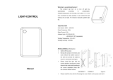
This product may carry approvals from a certifying agency or may be in compliance with EMC Directive. If
so, the product will carry approval insignia, like those shown here, on the product name rating plate.
®

Instruction Manual
245364-V
May 2002
P-6 Preface Rosemount Analytical Inc. A Division of Emerson Process Management
Model 755A

Instruction Manual
245364-V
May 2002
Rosemount Analytical Inc. A Division of Emerson Process Management Description and Specifications 1-1
Model 755A
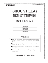
6 Digit LCD Display
ZERO Adjust
Rosemount Analytical
Model 755A
Oxygen Analyzer
PRESS CAL1 PRESS CAL 2
NORM REC OFFSET
SPAN Adjust
TEST Switch
ZERO
SPAN
SECTION 1
DESCRIPTION AND SPECIFICATIONS
1-1 OVERVIEW
The Model 755A Oxygen Analyzer provides
digital readout of the oxygen content of a
flowing gas sample. Oxygen is strongly
paramagnetic; other common gases, with only
a few exceptions, are weakly diamagnetic.
A front panel liquid crystal display provides
direct digital readout of oxygen concentration.
In addition a field-selectable voltage output is
provided as standard. An isolated current
output of 0 to 20 mA or 4 to 20 mA is
obtainable with the optional Current Output
Board. Current and voltage output may be
utilized simultaneously if desired.
The basic electronic circuitry is incorporated
into two master boards: The Control Board
Assembly and the Case Circuit Board
Assembly (see Figure 1-2, page 1-3). The
Control Board has a receptacle which accepts
optional circuit boards, thus permitting
inclusion of such features as current output.
1-2 OXYGEN RANGE ON FRONT PANEL
DIGITAL DISPLAY
The front panel LCD (liquid crystal display)
provides direct readout of oxygen
concentration from 0.00% to 100.00%.
Figure 1-1. Model 755A Oxygen Analyzer

Instruction Manual
245364-V
May 2002
1-2 Description and Specifications Rosemount Analytical Inc. A Division of Emerson Process Management
Model 755A
1-3 OXYGEN RANGES FOR RECORDER
READOUT
If desired, the recorder output may be set for
a fullscale range of 0 to 100% oxygen.
Alternatively, a desired portion of this overall
range may be selected for fullscale
presentation on the recorder. The selection is
made by an appropriate combination of scale
expansion and zero suppression.
Scale Expansion
Fullscale oxygen span for the recorder is
switch selectable for 1%, 2%, 5%, 10%, 20%,
or 100% oxygen.
Zero Suppression
The desired zero suppression is obtained as
the sum of (a) a jumper selectable fixed value
of 0%, 20%, 40%, 60% or 80% oxygen and
(b) a continuously adjustable value of 0% to
25% oxygen. Thus the electronic circuitry
provides the capability of setting the total zero
suppression for any desired value from 0% up
to a theoretical maximum of 105% oxygen.
However, the maximum usable zero
suppression is 99%, which is used in
establishing a range of 99% to 100%.
The effective zero suppression, in volts, may
be read on the digital display by placing the
front panel TEST Switch in position 4 and the
Reorder Oxygen Span Selection Switch in 1 X
gain position (i.e., 100% oxygen)
Example:
Desired oxygen range for recorder output:
99% to 100% oxygen.
Required span is 1% oxygen, obtained by
jumper position.
Required zero suppression is 99% oxygen.
Thus, fixed zero suppression of 80% oxygen
is selected by jumper position, and adjustable
zero suppression is set for 19% oxygen.
1-4 RECORDER VOLTAGE AND CURRENT
OUTPUTS
Voltage Outputs (Standard)
Provided a standard is a jumper selectable
voltage output of 0 to 10 mV, 0 to 100 mV, 0
to 1 V, or 0 to 5 V DC.
Isolated Current Output (Option)
An isolated current output is obtainable with
the optional Current Output Board, either
included with the Model 755A or added at a
later date in the field.
This option provides a current output of either 0 to
20mA or 4 to 20mA for a maximum of 850 ohms.
Refer to Section 8 Replacement Parts, for the
part number of the Isolated Current Output
option.
NOTE
Voltage and current outputs may be used
simultaneously, if desired.
1-5 AUTOMATIC PRESSURE COMPENSATION
The oxygen readout is automatically corrected for
pressure variations within 3% of the target value,
which may be set anywhere within the range of -
2.7 to 3.3 psig ±3 psig (-18.6 to 22.8 kPa ±21 kPa.
1-6 OPTIONS
a. Alarm
The analyzer has an alarm relay assembly
consisting of two single-pole, double-throw
relays, one each for the ALARM 1 and
ALARM 2 contacts. These relays may be
used to drive external, customer-supplied
alarm and/or control devices.
b. Case Mounting
The analyzer is supplied, as ordered, with
hardware for one of three mounting
arrangements: Panel, wall, or pipe stanchion.
c. Electrical Power
The analyzer is supplied, as ordered, for
operation on either 120 VAC, 50/60 Hz, or
240 VAC, 50/60 Hz.

Instruction Manual
245364-V
May 2002
Rosemount Analytical Inc. A Division of Emerson Process Management Description and Specifications 1-3
Model 755A
+
-
+
COM
MA
MV
TB2
NO
COM
NC
RESE
NO
CO
NC
RESET
NO. 1
NO. 2
HOT
GND
N
E
U
T
H
O
T
TB1
Zero Suppression
Adjustment
CAL2 Adjustment,
Pressure Compensation
CAL1 Adjustment,
Pressure Compensation
Location for Optional Current
Output Board
Control Board
ZERO Control
SPAN Control
Span -
Jumper Select
Recorder Output -
Jumper Select
Zero Offset -
Jumper Select
Recorder Output
TB2
Case Board
Transformer, Power T1
(Behind TB1)
Alarm Relay Assembly
(Alarm Option)
Case Heater
Assembly
AC Power
TB1
Detector/Magnet
Assembly
Detector/Magnet As-
sembly Shock
Mount
Fuse
AC Power
Fuse
Case Heater
Transducer
Figure 1-2. Model 755A Component and Adjustment Locations

Instruction Manual
245364-V
May 2002
1-4 Description and Specifications Rosemount Analytical Inc. A Division of Emerson Process Management
Model 755A
1-7 SPECIFICATIONS
a. General
1
Operating Range ........................... 0.00% to 100.0% oxygen
Recorder Range ............................ Selectable for 0% to 100% oxygen or for any desired span of 1%,
2%, 5%, 10%, 20% or 100% oxygen within the overall range.
Response Time ............................. (90% of fullscale) recorder output factory set for 20 seconds;
adjustable from 5 to 25 seconds.
Reproducibility (Digital Display)..... ±0.01% Oxygen ±2 counts.
Ambient Temperature Limits
Maximum ............................... 49°C (120°F) EXCEPT 38°C (100°F) for 99% to 100% oxygen.
Minimum ................................ -7°C (20°F) EXCEPT 4°C (40°F) for 99% to 100% oxygen.
Zero and Span Drift
2
...................... Within ±1% of fullscale (±2% of fullscale for 99% to 100% range)
per 24 hours, provided that ambient temperature does not change
by more than 11.1°C (20°F).
±2.5% of fullscale per 24 hours with ambient temperature change
over entire range.
Barometric Pressure
Compensation ....................... Oxygen readout automatically corrected to within ±1% of fullscale
for barometric pressure variations within ±3% of target value and
within ±2% of fullscale for barometric pressure variations within
±5% of target value.
The target may be set anywhere within range of -2.7 to 3.3 psig ±3
psig (-18.6 to 22.8 kPa ±21 kPa).
Exhaust vented to atmosphere.
b. Sample
Dryness ......................................... Sample dewpoint below 43°C (110°F), sample free of entrained
liquids.
Temperature Limits
Maximum ............................... 66°C (150°F)
Minimum ................................ 10°C (50°F)
Operating Pressure
Maximum ............................... 69 kPa (10 psig).
Minimum ................................ -13.1 kPa (-1.9 psig)
Flow Rate
3
Maximum ............................... 500 cc/min
Minimum ................................ 50 cc/min
Recommended ...................... 250 ±20 cc/min
Materials in Contact with
Sample Gas........................... 316 stainless steel, glass, titanium, Paliney No. 7, epoxy resin,
Viton-A, platinum, nickel.
1
Performance specifications based on recorder output.
2
Zero and span drift specifications based on following conditions: Operating pressure constant; ambient temperature change
from initial calibration temperature, less than 11.1 Celsius degrees (20 Fahrenheit degrees); deviation from set flow held to
within ±10% or ±20 cc/min, whichever is smaller.
3
Deviation from set flow would be held to within ±10% or ±20 cc/min, whichever is smaller. If so, zero and span drift will be
within specifications, provided that operating temperature remains constant.

Instruction Manual
245364-V
May 2002
Rosemount Analytical Inc. A Division of Emerson Process Management Description and Specifications 1-5
Model 755A
c. Electrical
Supply Voltage and Frequency
Standard ................................ 115 VAC ±10 VAC, 50/60 Hz
Optional ................................. 230 VAC ±10 VAC, 50/60 Hz
Power Consumption
Maximum ............................... 300 watts
Nominal.................................. 75 watts
Output
Standard ................................ Field selectable voltage output of 0 to 10mV, 0 to 100mV, 0 to 1V,
or 0 to 5VDC
Optional ................................. Isolated current output of 0 to 20mA or 4 to 20mA (with Current
Output Board)
Alarm Option.................................. High-Low Alarm
Contact Ratings ..................... 5 amperes, 240V AC, resistive load
5 amperes, 120V AC, resistive load
5 amperes, 28V DC, resistive load
Setpoint ......................................... Adjustable from 1% to 20% of fullscale
Deadband ...................................... Adjustable from 1% to 20% of fullscale (Factory set at 10% of
fullscale)
d. Physical
Mounting
Standard ................................ Panel mount
Optional ................................. Surface or stanchion mount accessory available
Enclosure Classification ................ Meets requirements for NEMA 3R
Air Purge Option
1
................... NFPA 496 (1989) Type Z purge
Weight ........................................... Approximately 32.5 lbs (14.74 Kg)
Dimensions.................................... Height: 13.5 (343 mm)
Width: 11.5 (294 mm)
Depth: 7.12 (181 mm)
1
When installed with user supplied components, meets requirements for Class I, Division 2 locations per National Electrical
Code (ANSI/NFPA 70) for analyzers sampling nonflammable gases. Analyzers sampling flammable gases must be pro-
tected by a continuous dilution purge system in accordance with Standard ANSI/NFPA 496-1986, Chapter 8. Consult factory
for recommendations.

Instruction Manual
245364-V
May 2002
1-6 Description and Specifications Rosemount Analytical Inc. A Division of Emerson Process Management
Model 755A
/