PC CHIPS M789CG (V3.0A) User guide
- Category
- Motherboards
- Type
- User guide
Page is loading ...
Page is loading ...

i
Motherboard User’s Guide
This publication, including photographs, illustrations and software,
is under the protection of international copyright laws, with all
rights reserved. Neither this manual, nor any of the material
contained herein, may be reproduced without the express written
consent of the manufacturer.
The information in this document is subject to change without
notice. The manufacturer makes no representations or warranties
with respect to the contents hereof and specifically disclaims any
implied warranties of merchantability or fitness for any particular
purpose. Further, the manufacturer reserves the right to revise this
publication and to make changes from time to time in the content
hereof without obligation of the manufacturer to notify any person
of such revision or changes.
Trademarks
IBM, VGA, and PS/2 are registered trademarks of International
Business Machines.
VIA is a registered trademark of VIA Technologies, Inc.
Microsoft, MS-DOS and Windows 98/ME/NT/2000/XP are
registered trademarks of Microsoft Corporation.
AMI is a registered trademark of American Megatrends Inc.
Other names used in this publication may be trademarks and are
acknowledged.
Copyright © 2004
All Rights Reserved
M789CG Series, V3.0B
CLE266/November 2004

ii
Motherboard User’s Guide
Table of Contents
Trademark ...................................................................................I
Static Electricity Precautions............................................................ III
Pre-Installation Inspection ................................................................ III
Features & Checklist Translations ........................................V
Chapter 1: Introduction............................................................ 1
Key Features ........................................................................................ 2
Package Contents ................................................................................5
Chapter 2: Motherboard Installation ..................................... 6
Motherboard Components................................................................... 7
I/O Ports ............................................................................................... 8
Installing Memory Modules ................................................................. 9
Jumper Settings .................................................................................. 11
Install the Motherboard.....................................................................12
Connecting Optional Devices............................................................13
Install Other Devices..........................................................................16
Expansion Slots..................................................................................18
Chapter 3: BIOS Setup Utility............................................... 20
Introduction .......................................................................................20
Running the Setup Utility ........................... …………………………...21
Standard CMOS Setup Page .............................................................22
Advanced Setup Page ........................................................................23
Power Management Setup Page........................................................26
PCI/Plug and Play Setup Page..........................................................28
Load Optimal Settings .......................................................................29
Load Best Performance Settings ........................................................29
Features Setup Page ..........................................................................29
CPU PnP Setup Page .........................................................................31
Hardware Monitor Page....................................................................32
Change Password ..............................................................................33
Exit .....................................................................................................33
Chapter 4: Software & Applications ..................................... 34
Introduction .......................................................................................34
Installing Support Software...............................................................35
Bundled Software Installation...........................................................37

iii
Motherboard User’s Guide
Static Electricity Precautions
Static electricity could damage components on this motherboard.
Take the following precautions while unpacking this motherboard
and installing it in a system.
1. Don’t take this motherboard and components out of their
original static-proof package until you are ready to install
them.
2. While installing, please wear a grounded wrist strap if
possible. If you don’t have a wrist strap, discharge static
electricity by touching the bare metal of the system chassis.
3. Carefully hold this motherboard by its edges. Do not touch
those components unless it is absolutely necessary. Put this
motherboard on the top of static-protection package with
component side facing up while installing.
Pre-Installation Inspection
1. Inspect this motherboard whether there are any damages to
components and connectors on the board.
2. If you suspect this motherboard has been damaged, do not
connect power to the system. Contact your motherboard
vendor about those damages.

iv
Motherboard User’s Guide
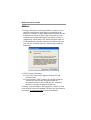
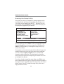
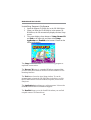
Notice:
1. Owing to Microsoft’s certifying schedule is various to every
supplier, we might have some drivers not certified yet by
Microsoft. Therefore, it might happen under Windows XP that
a dialogue box (shown as below) pop out warning you this
software has not passed Windows Logo testing to verify its
compatibility with Windows XP. Please rest assured that our
RD department has already tested and verified these drivers.
Just click the “Continue Anyway” button and go ahead the
installation.
2. USB 2.0 Driver Limitations:
2-1 The USB 2.0 driver only supports Windows XP and
Windows 2000.
2-2 If you connect a USB 2.0 hub to the root hub, plugging
USB devices into this hub, the system might not
successfully execute certain USB devices’ connection
because it could not recognize these devices.
Currently, we are working on such limitations’ solution. As soon
as the solution is done, the updated USB drive will be released to
our website:
www.pcchips.com for your downloading.
Page is loading ...
Page is loading ...
Page is loading ...
Page is loading ...
Page is loading ...
Page is loading ...
Page is loading ...
Page is loading ...
Page is loading ...
Page is loading ...
Page is loading ...
Page is loading ...
Page is loading ...
Page is loading ...
Page is loading ...
Page is loading ...
Page is loading ...

ii
Motherboard User’s Guide
xxii
Motherboard User’s Guide

1
Motherboard User’s Guide
Chapter 1 Introduction
This motherboard has a VIA C3 CPU onboard with front-side
bus speed up to 133MHz.
This motherboard integrates the VIA CLE266 Northbridge and
8235 Southbridge chipsets that support DDR 266MHz, Ultra
DMA 33/66/100/133 function and remarkably high system
performance under all types of system operations
It supports built-in USB 2.0 providing higher bandwidth. It
implements Universal Serial Bus Specification Revision 2.0
and is compliant with UHCI 1.1 and EHCI 1.0.
The motherboard supports the built-in AC’97 Codec, two 32-bit
PCI slots, one CNR (Communications and Networking Riser)
slot, and an onboard 10BaseT/100BaseTX Network interface
(optional). This motherboard integrates a 128-bit 3D/2D
graphics engine and a high-performance 3D accelerator.
In addition, this motherboard has a full set of I/O ports including
two PS/2 ports for mouse and keyboard, one serial port, one VGA
port, one parallel port. one LAN port (optional), audio jacks for
microphone, line-in and line-out, four back-panel USB2.0 ports
and onboard USB header USB1 providing two extra ports by
connecting the extended USB module to the motherboard.
This motherboard has all the features you need to develop a
powerful multimedia workstation. The board is FLEX ATX size
and has a power connector for an ATX power supply.

2
Motherboard User’s Guide
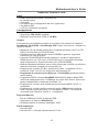
Key Features
The key features of this motherboard include:
CPU Type
• Supports the VIA C3 CPU onboard
• Supports 133 MHz Front-Side Bus
Chipset
There are VIA CLE266 Northbridge and 8235 Southbridge
in this chipset in accordance with an innovative and scalable
architecture with proven reliability and performance. A few of the
chipset’s advanced features are:
• High Performance CPU Interface: Support for VIA C3
processors; 133/100/66 MHz CPU Front Side Bus (FSB)
• High Bandwith 266 MB/sec 8-Bit V-Link Host Controller:
Supports 66 MHz V-Link Host Interface with total band-
width of 266 MB/sec
• Advanced High-Performance DDR/SDR DRAM Control-
ler: DRAM interface synchronous with host CPU (133/100
MHz) for most flexible configuration; Supports 4 banks up
to 2 GB DRAMs
• Integrated Graphics / Video Accelerator : 16/32/64 frame
buffer using system memory; Internal AGP 4x performance
• Concurrent PCI Bus Controller: 33 MHz operation, PCI 2.2
compliant, 32 bit 3.3V PCI interface with 5V tolerant inputs
• Fast Ethernet Controller: 1/10/100 MHz full and half
duplex operation
• UltraDMA-133/100/66/33 Master Mode EIDE Controller:
Transfer rate up to 133MB/sec to cover PIO mode 4, multi-
word DMA mode 2 drives, and UltraDMA-133 interface
• Direct Sound Ready AC’97 Digital Audio Controller:
AC’97 2.1 compliant

3
Chapter 1: Introduction
• Universal Serial Bus Controller: USB v2.0 and Enhanced
Host Controller Interface (EHCI) v1.0 compatible; USB
v1.1 and Universal Host Controller Interface (UHCI) v1.1
compatible
Memory Support
• Two 184-pin DIMM sockets for DDR memory modules
• Supports DDR266/200 memory bus
• Maximum installed memory is 2GB
Expansion Slots
• One CNR slot
• Two 32-bit PCI slots for PCI 2.2-compliant bus interface
Onboard IDE channels
• Two IDE Connectors
• Supports PIO (Programmable Input/Output) and DMA
(Direct Memory Access) modes
• Supports IDE Ultra DMA bus mastering with transfer rates
of 133/100/66/33 MB/sec
VGA
• Intergrated Graphics/Video Accelerator supports optimized
Shared Memory Architecture (SMA)
• Separate 128-bit data paths between north bridge and
graphics core for pixel data flow and texture/command
access
• Graphics engine clocks up to 133MHz decoupled from
memory clock
• High quality DVD video playback
AC’97 Codec
• 6- channel and compliant with Intel
®
AC’97 (REV. 2.3)
Spec, meeting with Microsoft
®
PC2001 requirements

4
Motherboard User’s Guide
• Advanced power management and power saving capabili-
ties.
• Stereo Line-in function shared with Surround out.
• High quality pseudo-differential analog CD Audio input.
• S/PDIF Output support: Output 96 / 48 kHz with 24 / 20 /16
bits
• Valuable add-on software technology: Support most industry
standards of PC 3D sound and unique karaoke function
support featured with microphone echo, key shifting, and
vocal cancellation.
Onboard I/O Ports
The motherboard has a full set of I/O ports and connectors:
• Two PS/2 ports for mouse and keyboard
• One serial port
• One parallel port
• One VGA port
• One LAN port (optional)
• Four back-panel USB2.0 ports
• Audio jacks for microphone, line-in and line-out
Fast Ethernet LAN (optional)
• 10Base-T/100Base-TX Physical Layer Solution
• Dual Speed – 100/10 Mbps
• MII Interface to Ethernet Controller/Configuration & Status
• Auto Negotiation: 10/100, Full/Half Duplex
• Meet All Applicable IEEE802.3, 10Base-T and 100Base-
TX Standards
USB 2.0
• Compliant with Universal Serial Bus Specification Revision
2.0
• Compliant with Intel’s Enhanced Host Controller Interface
Specification Revision 1.0

5
Chapter 1: Introduction
• Compliant with Universal Host Controller Interface Specifi-
cation Revision 1.1
• PCI multi-function device consists of two UHCI Host
Controller cores for full-/low-speed signaling and one
EHCI Host Controller core for high-speed signaling
• Root hub consists 4 downstream facing ports with inte-
grated physical layer transceivers shared by UHCI and
EHCI Host Controller, up to six functional ports
• Support PCI-Bus Power Management Interface Specifica-
tion release 1.1
• Legacy support for all downstream facing ports
BIOS Firmware
This motherboard uses AMI BIOS that enables users to configure
many system features including the following:
• Hard drives, diskette drives, and peripherals
• Power management
• CPU parameters and memory timing
• Hardware monitoring parameters
The firmware can also be used to set parameters for different
processor clock speeds.
Dimensions
• FLEX ATX form factor (230 x 170 mm)
Note: Hardware specifications and software items are subject to
change without notification.

6
Motherboard User’s Guide
Package Contents
Your motherboard package ships with the following items:
• The motherboard
• The User Guide
• One diskette drive ribbon cable (optional)
• One IDE drive ribbon cable
• The Software support CD
Optional Accessories
You can purchase the following optional accessories for this
mainboard.
• The Extended USB module
• The CNR v.90 56K Fax/Modem card
• Card Reader (You can buy your own Card Reader from the
third party, but please contact your local Card Reader
vendor on any issues of the specification and compatibility.
Note: You can purchase your own optional accessories from the
third party, but please contact your local vendor on any issues
of the specification and compatibility.

7
Chapter 2: Motherboard Installation
Chapter 2 Motherboard Installation
To install this motherboard in a system, please follow these
instructions in this chapter:
• Identify the motherboard components
• Install a CPU
• Install one or more system memory modules
• Make sure all jumpers and switches are set correctly
• Install this motherboard in a system chassis (case)
• Connect any extension brackets or cables to connectors/
headers on the motherboard
• Install peripheral devices and make the appropriate connec-
tions to connectors/headers on the motherboard
Note:
1. Before installing this motherboard, make sure jumper
JBAT1 is under Normal setting. See this chapter for
information about locating JBAT1 and the setting options.
2. Never connect power to the system during installation;
otherwise, it may damage the mainboard.

8
Motherboard User’s Guide
SPK1
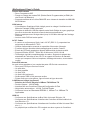
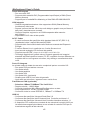
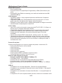
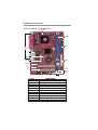
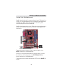
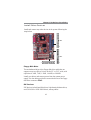
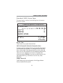
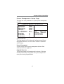
Motherboard Components
LABEL COMPONENTS
DIMM1/2 Two 184-pin DDR SDRAM sockets
IDE1/2 Primary/Secondary IDE connectors
ATX1 Standard 20-Pin ATX Power connector
USB1 Front Panel USB header
FDC1 Floppy Disk Drive connector
PANEL1 Front Panel Switch/LED header
SYSTEM_FAN1 System Fan connector
JBAT1 Clear CMOS jumper
SPK1 Speaker header
PCI 1-2 32-bit PCI slots
CD1 Analog Audio Input header
DIMM
IDE1
IDE2
SYSTEM_FAN1CNR1
PANEL1
JBAT1
FDC1
PCI
CD1
AUDIO2
CPU_FAN1
J5
USB1
ATX1
IO
PORTS

9
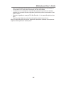
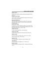
Chapter 2: Motherboard Installation
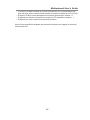
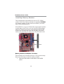
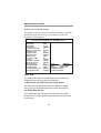
PS/2 Mouse
PS/2 Keyboard
Parallel Port (LPT1)
Serial Port COM1
VGA Port
LAN Port (optional)
USB Ports
Audio Ports
Use the upper PS/2 port to connect a PS/2
pointing device.
Use the lower PS/2 port to connect a PS/2
keyboard.
Use the Parallel port to connect printers or
other parallel communications devices.
Use the COM port to connect serial devices
such as mice or fax/modems. COM1 is
identified by the system as COM1.
Use the VGA port to connect VGA devices.
Connect an RJ-45 jack to the LAN port to
connect your computer to the Network.
Use the USB ports to connect USB devices.
Note: The lower USB port located beside
the VGA port is shared with the J5 header.
Use the three audio ports to connect audio
devices. The first jack is for stereo Line-In
signal. The second jack is for stereo Line-
Out signal. The third jack is for Microphone.
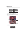
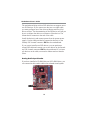
I/O Ports
The illustration below shows a side view of the built-in I/O ports
on the motherboard.
LABEL COMPONENTS
AUDIO2 Front Panel Audio header
J5 USB Card Reader header
CPU_FAN1 CPU Fan connector
CNR1 Communications Networking Riser slot
Shared
with J5
(Optional)

10
Motherboard User’s Guide
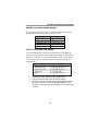
Installing Memory Modules
This motherboard accommodates two 184-pin 2.5V DIMM
sockets (Dual Inline Memory Module) for unbuffered DDR266/
200 memory modules (Double Data Rate SDRAM), and maxi-
mum 2.0GB installed memory.
DDR SDRAM is a type of SDRAM that supports data transfers
on both edges of each clock cycle (the rising and falling edges),
effectively doubling the memory chip’s data throughput. DDR
DIMMs can synchronously work with 200 MHz or 266 MHz
memory bus, providing 1.6 GB/s or 2.1 GB/s data transfer rate.
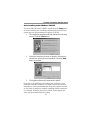
Memory Module Installation Procedure
These modules can be installed with up to 2 GB system memory.
Refer to the following to install the memory module.
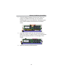
1. Push down the latches on both sides of the DIMM
socket.
DIMM1
DIMM2

11
Chapter 2: Motherboard Installation
3. Install the DIMM module into the socket and press it
firmly down until it is seated correctly. The socket latches
are levered upwards and latch on to the edges of the
DIMM.
4. Install any remaining DIMM modules.
2. Align the memory module with the socket. There is a
notch on the DIMM socket that you can install the
DIMM module in the correct direction. Match the cutout
on the DIMM module with the notch on the DIMM
socket.

12
Motherboard User’s Guide
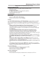
Jumper Settings
Connecting two pins with a jumper cap is SHORT; removing a
jumper cap from these pins, OPEN.
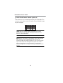
JBAT1: Clear CMOS Jumper
Use this jumper to clear the contents of the CMOS memory. You
may need to clear the CMOS memory if the settings in the Setup
Utility are incorrect and prevent your mainboard from operating.
To clear the CMOS memory, disconnect all the power cables from
the motherboard and then move the jumper cap into the CLEAR
setting for a few seconds.
Note: To avoid the system unstability after clearing CMOS, we
recommend users to enter the main BIOS setting page to “Load
Optimal De-faults” and then “Save Changes and Exit”.
Function Jumper Setting
Normal Short Pins 1-2
CLEAR CMOS Short Pins 2-3
1
JBAT1

13
Chapter 2: Motherboard Installation
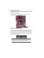
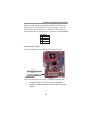
Install the Motherboard
Install the motherboard in a system chassis (case). The board is a
FLEX ATX size motherboard. You can install this motherboard in
an ATX case. Make sure your case has an I/O cover plate
matching the ports on this motherboard.
Install the motherboard in a case. Follow the case manufacturer’s
instructions to use the hardware and internal mounting points on
the chassis.
1
Connect the power connector from the power supply to the
ATX1 connector on the motherboard.
If there is a cooling fan installed in the system chassis, connect
the cable from the cooling fan to the SYSTEM_FAN1 fan
power connector on the motherboard.
Connect the case switches and indicator LEDs to the PANEL1
header.
ATX1
PANEL1
SYSTEM_FAN1
1

14
Motherboard User’s Guide
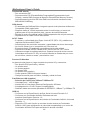
Connecting Optional Devices
Refer to the following for information on connecting the
motherboard’s optional devices:
SPK1: Speaker Header
Connect the cable from the PC speaker to the SPK1 header on
the motherboard.
Pin Signal Pin Signal
1 SPKR 2 NC
3 GND 4 +5V
SPK1
1
Here is a list of the PANEL1 pin assignments.
Pin Signal Pin Signal
1 HD_LED_P(+) 2 FP PWR/SLP(+)
3 HD_LED_N(-) 4 FP PWR/SLP(-)
5 RESET_SW_N(-) 6 POWER_SW_P(+)
7 RESET_SW_P(+) 8 POWER_SW_N(-)
9 RSVD_DNU 10 KEY
AUDIO2
1
J5
1
USB1
1

15
Chapter 2: Motherboard Installation
AUDIO2: Front Panel Audio Header
This connector allows the user to install auxiliary front-oriented
microphone and line-out ports for easier access.
Pin Signal Pin Signal
1 AUD_MIC 2 AUD_GND
3 AUD_MIC_BIAS 4 AUD_VCC
5 AUD_FPOUT_R 6 AUD_RET_R
7 HP_ON 8 KEY
9 AUD_FPOUT_L 10 AUD_RET_L
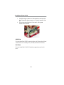
USB1: Front panel USB Header
The motherboard has USB ports installed on the rear edge I/O
port array. Additionally, some computer cases have USB ports at
the front of the case. If you have this kind of case, use auxiliary
USB header USB1 to connect the front-mounted ports to the
motherboard.
1. Locate the USB1 header on the motherboard.
2. Plug the bracket cable onto the USB1 header.
3. Remove a slot cover from one of the expansion slots on
the system chassis. Install an extension bracket in the
opening. Secure the extension bracket to the chassis with
a screw.
Pin Signal Pin Signal
1 VERG_FP_USBPWR0 2 VERG_FP_USBPWR0
3 USB_FP_P0(-) 4 USB_FP_P1(-)
5 USB_FP_P0(+) 6 USB_FP_P1(+)
7 GROUND 8 GROUND
9 KEY 10 USB_FP_OC0
Page is loading ...
Page is loading ...
Page is loading ...
Page is loading ...
Page is loading ...
Page is loading ...
Page is loading ...
Page is loading ...
Page is loading ...
Page is loading ...
Page is loading ...
Page is loading ...
Page is loading ...
Page is loading ...
Page is loading ...
Page is loading ...
Page is loading ...
Page is loading ...
Page is loading ...
Page is loading ...
Page is loading ...
Page is loading ...
Page is loading ...
-
 1
1
-
 2
2
-
 3
3
-
 4
4
-
 5
5
-
 6
6
-
 7
7
-
 8
8
-
 9
9
-
 10
10
-
 11
11
-
 12
12
-
 13
13
-
 14
14
-
 15
15
-
 16
16
-
 17
17
-
 18
18
-
 19
19
-
 20
20
-
 21
21
-
 22
22
-
 23
23
-
 24
24
-
 25
25
-
 26
26
-
 27
27
-
 28
28
-
 29
29
-
 30
30
-
 31
31
-
 32
32
-
 33
33
-
 34
34
-
 35
35
-
 36
36
-
 37
37
-
 38
38
-
 39
39
-
 40
40
-
 41
41
-
 42
42
-
 43
43
-
 44
44
-
 45
45
-
 46
46
-
 47
47
-
 48
48
-
 49
49
-
 50
50
-
 51
51
-
 52
52
-
 53
53
-
 54
54
-
 55
55
-
 56
56
-
 57
57
-
 58
58
-
 59
59
-
 60
60
-
 61
61
-
 62
62


PC CHIPS M789CG (V3.0A) User guide
- Category
- Motherboards
- Type
- User guide
Ask a question and I''ll find the answer in the document
Finding information in a document is now easier with AI
Related papers
-
Mercury M789CLU (V1.2) Specification
-
PC CHIPS M791G (V1.0a) Specification
-
-
-
-
-
ECS M985G Series User manual
-
-
-
ECS T12 (V1.0a) User manual
Other documents
-
Canyon CNR-USBHUB5N Datasheet
-
Conceptronic C05-128 Datasheet
-
A-Link HUBU4 Datasheet
-
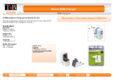 T'nB ACMPFR2A Datasheet
-
-
Lindy 51058 User manual
-
-
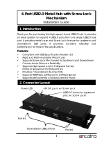 ANTAIRA USB-HUB4K Installation guide
-
-
Sitecom CN-029 Datasheet

