GE ZV750 Installation guide

Category
Cooker hoods
Type
Installation guide

This manual is also suitable for

Monogram ZV750 is a 36-inch range hood designed for efficient ventilation in your kitchen. It offers various features to enhance your cooking experience and maintain a clean and fresh environment. With its powerful motor, the hood effectively removes smoke, grease, and odors from the air, ensuring a pleasant cooking atmosphere. The hood's sleek design and decorative duct cover seamlessly integrate into your kitchen décor, complementing your appliances and enhancing the overall aesthetics of your space.

Monogram ZV750 is a 36-inch range hood designed for efficient ventilation in your kitchen. It offers various features to enhance your cooking experience and maintain a clean and fresh environment. With its powerful motor, the hood effectively removes smoke, grease, and odors from the air, ensuring a pleasant cooking atmosphere. The hood's sleek design and decorative duct cover seamlessly integrate into your kitchen décor, complementing your appliances and enhancing the overall aesthetics of your space.

GE Monogram ®
Installation
Instructions
36" Vent Hood
Model
ZV750
gefi_re you begin--Read these instructions completely and carefldly.
IMPORTANT: Save these instructions for local inspector's use.
IMPORTANT: OBSERVE ALL GOVERNING CODES AND ORDINANCES.
NOTE TO INSTALLER: Be sure to leave these instructions with the (;onsmner.
NOTE TO CONSUMER: Keep these instructions with yore _ Use and (_are Book t()i"
fllture reference.
_!lW'.l;tL'lh'[ell This appliance must be properly grounded. See "Electrical Supply", page 4. i
If wm have questions concerning the installa-
tion of this product, call the GE Answer
Center °' Consmner Intormation Service at
800.626.9000, 94 horn's a day, 7 days a week.
If wm received a damaged vent hood, you
should contact yore" dealer.
CAUTION!
Due to the weight and size of these vent hoods
and to reduce the risk of personal ii_jury or
damage to the product, T_VO PEOPLE ARE
REQUIRED FOR PROPER INSTALLATION.
WARNING!
To reduce the risk of fire or electric shock, do
not use this range hood with any external
solid-state speed control device. Any such
alteration fl'om original thctory wiring could
result in damage to the trait ai'ld/or create an
electrical safety hazard.
To reduce the risk of fire and to properly
exhaust aiI; be sm'e to duct air outdoors. Do
not vent exhaust air into spaces within walls or
ceilings or into attics, crawl spaces or garages.
_\:ARNING: TO REDUCE THE RISK OF FIRE,
USE ONINMETAL DUCT_VORK.
TO REDUCE THE RISK OF FIRE, ELECTRIC
SHOCK OR INJURY TO PERSONS,
OBSERVE THE FOI_LOWING:
A. Use this trait only in the rammer intended
bv the mamlthcturer. If you have arJy q ues-
tions, contact the mamffacturer.
B. Beti)re servicing or cleaning trait, switch
power oil at service panel and lock service
panel to prevent power fl'om being switched
on accidentally. If the service panel cam_ot be
locked, thsten a tag or prominent warning
label to the panel.
For general ventilating use only. Do not use
to exhaust hazardous or explosive materials
and vapors.
Installation work and electrical wiring must be
done by qualified person (s). In accordance
with all applicable codes and standards
including fire-rated construction.
Sufficient air is needed for proper combustion
and exhausting of gases through the flue
(chimney) of tirol burning equipment to
prevent back drafting. Follow the heating
eq uipm ent manuthcturer's guideline and
satiety standards such as those published bv the
National Fire Protection Association (NFPA),
and the American Society for Heating, Refl'ig-
eration and Air Conditioning Engineers
(ASHRAE), and the local code authorities.
Con_n_
Design Information
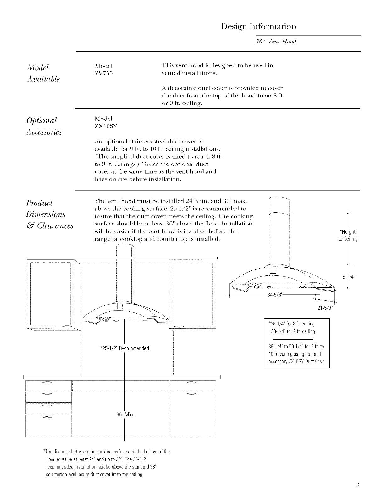
Models available .................................................................................................................................. 3
Optional Accessories ........................................................................................................................... 3
Product Dimensions & Clearances .................................................................................................... 3
Advance Plmming ............................................................................................................................... 4
Electrical Supply .................................................................................................................................. 4
Installation Preparation
Duct Fittings ....................................................................................................................................... 5
Tools and Materials Required ............................................................................................................ 6
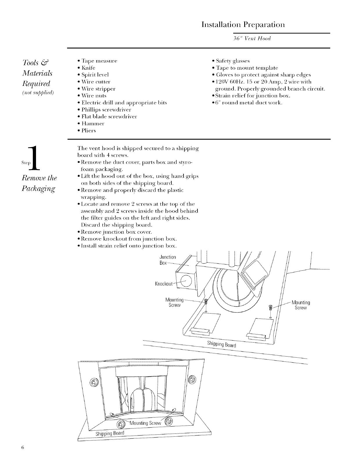
Step 1: Remove the packaging ........................................................................................................... 6
Installation
Step 2: Check Installation Hardware ................................................................................................. 7
Step 3: Mount Template ..................................................................................................................... 7
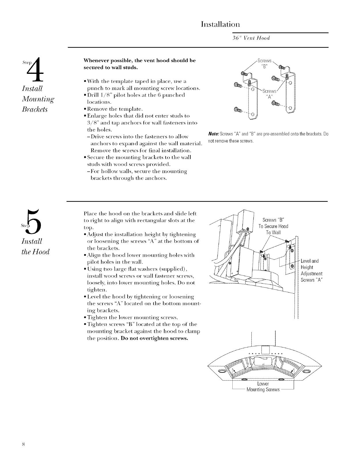
Step 4: Install Motmting Bracket ....................................................................................................... 8
Step 5: Install the Hood ...................................................................................................................... 8
Step 6: Install Duct Bracket ................................................................................................................. 9
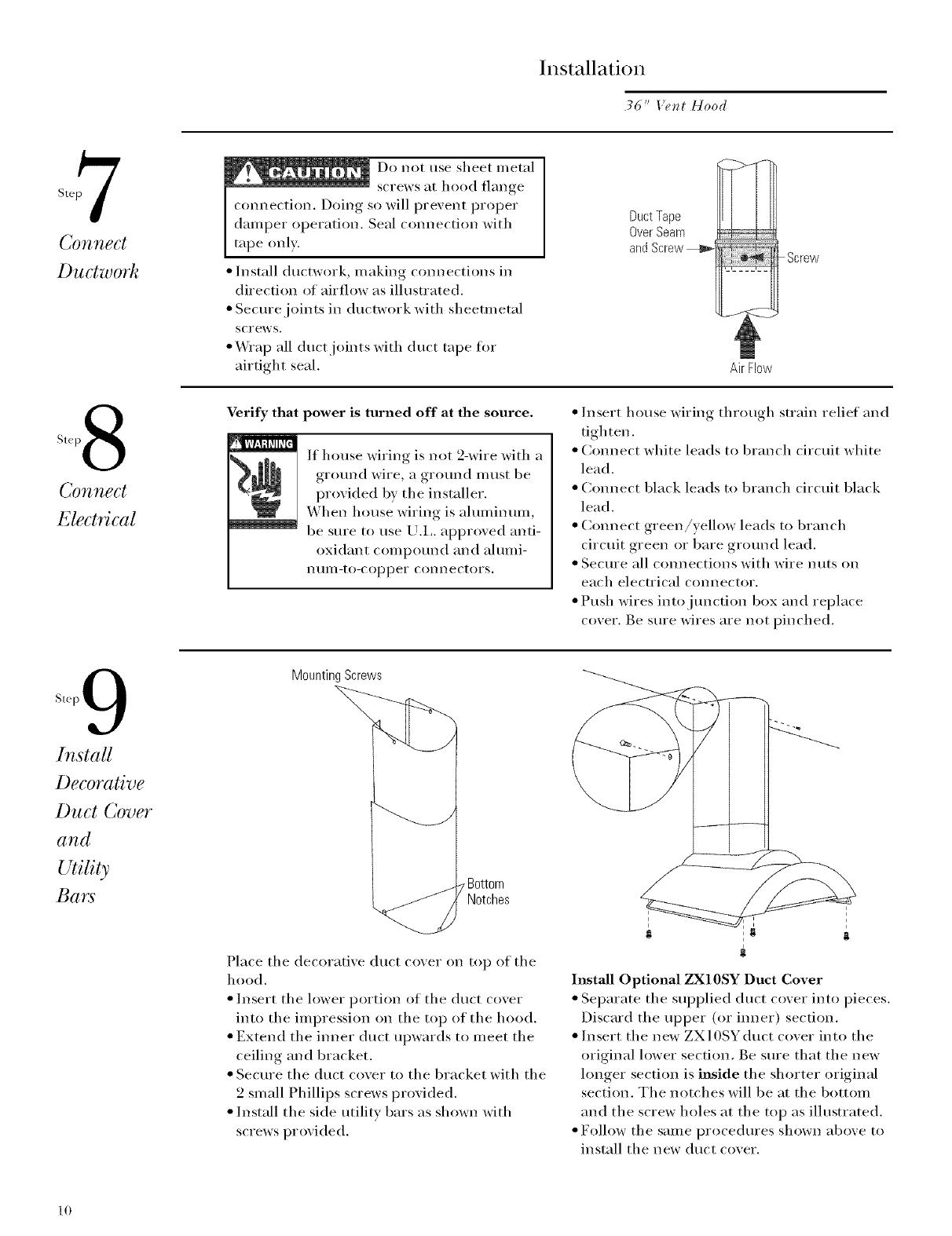
Step 7: Comaect Ductwork ................................................................................................................ 10
Step 8: Cmmect Electrical ................................................................................................................. 10
Step 9: Install Decorative Duct Cover. .............................................................................................. 10
Step 10: Install Filters ........................................................................................................................ 11
Step 11 : Finalize Installation ............................................................................................................. 11
Design hdbrmation
36" Ve_t Hood
Model
Available
Optional
Accessories
Model
ZV750
This xent hood is designed to be used in
xented installations.
A decorative duct coxer is proxided to coxer
the duct fl'on_ the top of the hood to an S ti.
or 9 ft. ceiling.
Model
ZX 10SY
An optional stainless steel duct cover is
available for 9 ft. to 10 ft. ceiling installations.
(The supplied duct cover is sized to reach 8 It.
to 9 ft. ceilings.) Oi'der the optional duct
cover at the same time as the vent hood and
have on site befi)re installation.
Product
Dimensions
& Clea" ances
o
[
o II
L o
o
Tile xent hood m ust be installed 24" rain. and 30" max.
aboxe tile cooking sm'face. 25-1/2" is recommended to ]_
insm'e that tile duct coxer meets tile ceiling. The cooking _ _-_
surthce should be at least 36 aboxe tile floor. Installation
will be easier if tile xeilt hood is installed before tile
_ meig_t
range or cooktop and comatertop is installed, to Ceiling
21-5/8"
<=> "26-1/4" for 8 ft. ceiling
38-1/4" for 9 ft. ceiling
"25-1/2" Recommended 38-1/4" to 50-1/4" for 9ft. to
10ft. ceiling usingoptional
accessoryZXlOSYDuct Cover
I
o
36"Min.
*The distance betweenthe cooking surfaceandthe bottom of the
hoodmust beat least24" and upto 30". The25-1/2"
recommendedinstallation height, abovethe standard 36"
countertop, will insure duct coverfit to the ceiling.
Design Infi)rmation
36" ge_t Hood
Advance
Plannin, g
Ductwork
Determine tile exact location of tile vent hood.
Plan tile route for venting exhaust to tile
outdoors.
Use tile shortest and straightest duct route
possible. For satistactory perflwmance, duct
run should not exceed 100 feet equivalent
length tot any duct configm_ations.
• Refer to "Duct Fittings" chart to compute tile
maxim mn permissable length tot duct rims to
tile outdoors.
Install a wall cap with damper or roof cap at
tile exterior opening.
Electrical
Supply
Warning, for
Personal
Safety:
Reillove house
fllse or open
circuit breaker betore
begimfing installation.
Do not IlSe aI] extensi(m
cord or adapter plug with
this appliance. Follow
National electrical codes
or prevailing local codes
and ordinances.
Electrical supply
This vent hood must be supplied with 120V,
60Hz., and comaected to an individual, properly
gro/mded branch circuit, protected bv a 15 o1"
90 ampere circuit breaker or time delay fllse.
• Wiring illtlSt be 2 wire with grotmd.
• If tile electrical supply does not meet tile
above requirements, call a licensed electrician
before proceeding.
• Route wiring as close to tile installation
location as possible, in tile ceiling or soffit.
Cmmect tile wiring to tile house wiring in
accordance with local codes.
Grounding Instruction
Tile grounding conductor must be cmmected to
a gro/md metal, permanent wiring system, or an
equipment-gro/mding terminal or lead on tile
hood.
Warning: Tile improper comaec-
tion of tile equipmerJt-ground-
ing conductor can result in a
risk of electric shock. Check with
a qualified electrician or service
representative if you are in doubt whether
tile appliance is properly gro/mded.
Installation Preparation
36" l,'e_H Hood
Dztct
Use this chart to
conlpute I11axilIl tlI/l
permissable lengths
I_i)I"duct I'/lI]S to
outdoors.
Total
Equivalent Quantity Equivalent
Duct Piece Dimensions i,ength* Used I,ength
Round, 1 tL
straight (per tiler
length)
3-1/4" x 10" 1 ti.
straight (pet" toot
length)
90° elbow 15 ft.
42)° elbow 9 ft.
3-1/4" x 1()"
90._elbow 15 il.
3-1/4" x 10"
45° elbow 9 ft.
3-1/4" x 10"
90'_flat elbow 20 ft.
_ 6" round to
3-1/4" x 10" or
3- 4 x 24 trmsition 1 ft.
3-1/4" x 10"
to 6" round transition 5 ft.
_,, )_ 6" round to
3-1/4" x ll)"
tr msition 9()_ elbow 5 ft.
3-1/4" x 10" to 6" round
tr msition 90 ° elbow l 5 ti.
Note: Donotexceedmaximum
permissahleequivalentlengths!
Maximum ductlength:
100foot for rangehoods.
Flexible ducting:
If flexible metal
ducting is ttsed, all
tile equivalent teet
values in tile table
should be doubled.
Tile flexible metal
duct should be
straight and smooth
and extended as
much as possible.
Do NOT use flexible
plastic ducting.
Note: Anyhomeventilation
system,suchasaventilation
hoed,mayinterrupttheproper
flow ofcombustionairand
exhaustrequiredbyfireplaces,
gasfurnaces,gaswater I_eaters
andothernaturallyvented
systems.To mMmizethechance F>
of interruptionofsuchnaturally
%
ventedsystems,follow theheating
equipmentmanufacturer's
guidelinesandsafeS/standards
suchasthosepublishedbyNFPA
andASHRAE.
R,.)ut'_d
wall cap
with d re]per 30 ft.
_ 3-1/4" x 10" wall cap
]dth d unper 30 fl.
Round
roof cap 26 ft.
Round
roof vent 24 ft.
*Actual length of straight duct plus duct fitting Total Duct Run
equivalent. Equivalentlength of duct pieces are based
onactual tests conducted by GEEvaluation Engineer-
ing and reflect requirements for good venting
performance with any ventilation hood.
Installation Preparation
36" V_,_I Hood
7bots &
Materials
Required
(not s,])Jg@d)
Tape measure
I0aife
Spirit level
Wire cutter
Wire stripper
_vVire nuts
Electric drill and appropriate bits
Phillips screwdriver
Flat blade screwdriver
Hanlnler
Pliers
Salety glasses
Tape to mount mmplate
Gloves to protect against sharp edges
12(W 60Hz. 15 or 20 _Mnp, 2 wire with
ground. Properly grounded branch circuit.
Strain relief for jun ctinn box.
6" rotmd metal duct work.
The vent hood is shipped secured to a shipping
board with 4 screws.
Remove the duct cover, parts box and styro-
ti:mm packaging.
I,ifl the hood ()tit of the box, using hand grips
on both sides of tile shipping hoard.
Remove and properly discard the plastic
wrapping.
Locate and renlove 2 screws at the top of the
assembly and 2 screws inside the hood behind
the filter guides on the lett and right sides.
Discard the shipping board.
Relnove.jullctioI_ box cover.
Rein ore knockout tl"om j unction box.
Install strain relief onto jui_ctioia box.
Junction
Knockout_
Mountin
Screw
/Mounting
Screw
ShippingBoard
Screw
0ard
Installation
36" Ve_t Hood
(/heck
hl,stallation
Hardware
s'3
Ductwork,
WMng,
Hood
Attachment
Locations
Locate the hardware accessory box packed
with range hood and check contents.
Wall
Fasteners
2 Mounting
@ Brackets
Yg
_, 2PhillipsHeadScrews
UtilityBarswith Screws 3 Filters
2Large
FlatWashers
10
Wood
Screws
Decorative
Duct
Cover
i
Wall Mount Template
To determine ductwork locations:
Locate the template packed with the litera-
ttlre.
Determine the exact installation location.
-Measm'e 36" fl'om the floor to the top of
the cooking stlrfhce. Add 25-1/2" recom-
mei_ded space fl'om the cooking sui'filce to
bottom of hood. Mark that location.
-Use a level to draw a straight pencil line on
the wall.
-Tape the template in position along the
penciled line. CHECK TO BE SURE
TEMPLATE IS LEVEl.
Measure fi'oln the peak of the hood to the
ceiling as indicated. The dilnei_sioi_ should
be:
-26-1/4" to 38-1/4" for 8 ft. to 9 fi. ceilings.
-38-1/4" to 50-1/4" for 9 ft. to lO fL ceilings
this installation requires ZX 10SY accessory
(hlct cover.
CEILING DUCTING
If ductwork will vent straight up to the ceiling:
Llse a level to draw a line straight up, fl'om
the centerline on the template to the ceiling.
Measm'e 3-1/2" from the back wall to the
centerline of a 6-1/2" dia. hole on the
ceiling.
Note: Ifdrywallisnotpresent,adddrywallthicknesstothe
3-1/2"dimension.
31/2"
CenterlineT(
VENTDUCTING
6-1/2" Dia.Hole,
6" Min.Above
BracketLocation
WALL DUCTING
If ductwork will vent to the rear:
Use the level to draw a line straight up fl'om
the cei_terline on the telnplate.
Measure at least 6" above the bracket location
shown on the template to the centerline of
the 6-1/2" dia. duct hole. (Hole may need to
be elongated tor duct elbow.)
HOUSE WIRING LOCATION:
• The junction box is located on the top of the
hood, at the fl'ont right side.
Route house wiring as close to the installation
location as possible; through the ceiling,
soltit or back wall. Wiring should enter at
least 4" above the bracket on the right side.
Installation
36" Ve_t Hood
2 e_
St
hi, stall
Mounting
Brackets
Whenever possible, the vent hood should be
secured to wall studs.
*With the template taped in place, use a
punch to mark all mounting screw locations.
Drill 1/8" pilot holes at tile 6 punched
locations.
Remove tile template.
Enlarge holes that did not enter studs to
3/8" and tap anchors tor wall tasteners into
tile holes.
-Drive screws into tile tasteners to allow
anchors to expand against tile wall material.
Remove tile screws for final installation.
Secure tile mounting brackets to tile wall
studs with wood screws provided.
-For hollow walls, secure tile mounting
brackets through tile anchors.
Note: Screws'W' and"B"arepre-assembbdontothebrackets.Do
notremovethesescrews.
5
Install
the Hood
Place tile hood on tile brackets and slide left
to right to align with rectangular slots at tile
top.
• At!just the installation height by tightening
or loosening tile screws "A" at tile bottom of
the brackets.
• Align tile hood lower mounting holes with
pilot holes in tile wall.
Using two large flat washers (supplied),
install wood screws or wall tastener screws,
loosely, into lower mounting holes. Do not
tighten.
Level tile hood by tightening or loosening
tile screws "A" located on tile bottom inount-
ing brackets.
Tighten tile lower mounting screws.
Tighten screws "B" located at tile top of tile
mounting bracket against tile hood to clamp
tile position. Do not overtighteu screws.
\
Screws"B"
ToSecureHood
ToWall
-Leveland
Height
Adjustment
Screws'W'
Lower
MountingScrews
Installation
36" Ve_H Hood
Install Duct
Bracket
(/br vertical exhau,sO
Install the 2 small screws into the sides of the
duct bracket. Remoxe the scre_s. This will
insm'e ease of final installation.
Temporarily install a piece of 6" duct cut to
length bet_een the hood outlet and the
ductwork at the ceiling.
Position the upper duct bracket behind the
duct and against the wall and ceiling.
Llse a level to check that duct is x ertical and
duct bracket is centered.
Mark the 4 screw locations of the bracket.
Remoxe the bracket and temporary duct
section.
Drill 1/8" pilot holes in marked bracket
location.
If pilot holes do not enter studs, enlarge the
holes 3/8" and install _all thstener anchors,
Drixe screws into the
thsteners to allow anchors
to expand against the _all
material, Remox e the _"
scre_ s,
Secure the bracket to the
ceiling and wall with wood
screws ai]d/or _all
fasteI] er screws,
Duct
Work
_teBA
Install Duct
Bracket
(/br ho)'izo_?lal exhau,sO
The upper duct bracket should be installed
against the ceiling. This bracket will hold the
decorative duct cover in place at the top.
Install the 2 small screws into the sides of the
duct bracket, Remove the screws, This will
insm'e ease of final installation.
Position the bracket against the wall and
ceiling. (:enter the bracket using marked
centerline of the hood,
Use a pencil to mark the bracket location
along its outside edges,
Temporarily place the decorative duct cover
on top of the hood and extend the im]er
portion to meet the ceiling,
The duct cover should be level and align with
marks for bracket,
Rein ove the duct cover,
Place bracket against marked location and
mark the 4 screw locations,
Drill 1/8" pilot holes in marked location,
If pilot holes do not enter studs, enlarge the
holes 3/8" and install wall thstener anchors,
Drive screws into the thsteners to allow
anchors to expand against the wall material,
Remove the screws.
Secure the bracket to the ceiling and wall
with wood screws and/or wall thstei]er
screws.
9
Installation
36" Ve_t Hood
7
Connect
Ductwork
Do not use sheet metal
screws at hood flange
connection, Doing so will prevent proper
damper operation, Seal connection with
tape only.
Install ductw()rk, making com_ections in
direction of airflow as illustrated.
Secure joints in ducrwork with sheetm etal
screws.
Wrap all duct joints with duct tape fin.
airtight seal,
Duct Tape
Over Seam
and Screw _i
Screw
AirFlow
Step 8
Connect
Electrical
Verify that power is turned off at the source.
If house wiring is not 2-wire with a
ground wire, a ground must be
provided by the installer.
When house wiring is aluminum,
be sure to use U.L. approved anti-
oxidant compound and alumi-
ntlul-to-copper connectors.
Insert house wiring through strain relief and
tighten,
Connect white leads to branch circuit white
lead,
Connect black leads to branch circuit black
lead,
Connect green/yellow leads to branch
circuit green or bare ground lead,
Secure all connections with wire nuts on
each electrical connector,
Push wires into junction box and replace
cover. Be sure wires are not pinched.
Step 9
lnstaU
Decorative
Duct Cover
and
Utility
Bars
Mounting Screws
Notches
Place tile decorative duct cover on top of tile
hood,
Insert tile lower portion ot tile duct cover
into the impression on the top of the hood,
Extend the inner duct upwards to meet the
ceiling and bracket,
Secure the duct cover to the bracket with the
2 small Phillips screws provided,
Install the side utility bars as shown with
screws provided.
i
i
i
Install Optional ZX10SY Duct Cover
Separate tile supplied duct cover into pieces.
Discard tile upper (or imaer) section.
Insert tile new ZX10SYduct cover into tile
original lower section, Be sure that tile new
longer section is inside tile shorter original
section. Tile notches will be at tile bottom
and tile screw holes at tile top as ilh|strated.
• F(>llow tile saule procedtlres shown above to
install tile new duct cover.
10
Installation
36 _' Ve_l Hood
hl,stall Filter:s
Remove protective film on filters.
Tip the filter into the lower slots at the rear
of the opening, lift the filter and pull the
knob fin'ward until the filter rests on the
slots.
To relnove the filters, grasp the knob and
push the filter towards the rear and tilt
downwards.
Finafize
Installation
Remove protective film covering the control
panel on the fl'ont thee of the hood and anv
remaining packaging materials.
Reter to the Use and Care book fi)r
operating instructions.
11
Monogram:
General Electric Company
Louisville, KY40225
Note: While performing installations described in this book,
safety glasses or goggles should be worn.
Mom_o,ral, inoduct or s_,rvic_s call (;E A _z_w_rC_,llle__'
_o_l_ume_ D@_matio_z se_vi_ e at 800.626.2000 a_9'
Zime, day or _zigfiZ.
l,). Mo_og'_am Io_zd se_vi_ e Dzyou_ an,a, tail
1-800-444-1845.
N()TE: P:oauct implovemenl is _ containing endeavo: _I Gene_ d
Electric¸ Theret_>re. malerials, appearance and _pecificalions are
sul_iecl Io change wilhom nolice
Pub. N_. 49-8990-1
Dwg. N_}. 164D3333P214
(0 2000 GE Appli;m(es
(N.D. 6] 2) 5/00
Printed in Italy
  • Page 1 1
  • Page 2 2
  • Page 3 3
  • Page 4 4
  • Page 5 5
  • Page 6 6
  • Page 7 7
  • Page 8 8
  • Page 9 9
  • Page 10 10
  • Page 11 11
  • Page 12 12

GE ZV750 Installation guide

Category
Cooker hoods
Type
Installation guide
This manual is also suitable for

Monogram ZV750 is a 36-inch range hood designed for efficient ventilation in your kitchen. It offers various features to enhance your cooking experience and maintain a clean and fresh environment. With its powerful motor, the hood effectively removes smoke, grease, and odors from the air, ensuring a pleasant cooking atmosphere. The hood's sleek design and decorative duct cover seamlessly integrate into your kitchen décor, complementing your appliances and enhancing the overall aesthetics of your space.

Ask a question and I''ll find the answer in the document

Finding information in a document is now easier with AI