KitchenAid 9755235 User manual

Category
Ovens
Type
User manual
®
HOME APPLIANCES
R
Part No. 9755235 Rev. A
Tip Over Hazard
A cMId or adult can tip the range and be
kUled.
Connect anti-tip bracket to rear range foot.
Reconnect the anti-tip bracket, if the range
is moved.
Failure to follow these instructions can
result in death or serious burns to children
and adults.
I
a
these _n,
O_So
IMPORTANT :
Installer: Leave Installation instructions
with the homeowner.
Homeowner: Keep Installation
instructions and anti-tip bracket
template for future reference.
Save Installation Instructions for local
electrical inspector's use.
30" (76.2 c
Seal urner
F in
m
n
with seff-cmeaning thermal/convection oven
Before you start...
Your safety and the safety of others
are very important.
Wehaveprovided many important safety messagesin
this manuaIand on your appliance. Always readand
obeyall safety messages.
This isthe safety abrt symb0i.
This symb0t abrts you to potential hazards
that can kiii or hurt you and others.
Ati safety messageswiii f0ii0w the safety alert symbol
and eitherthe word "DANGER"or "WARNING".These
words mean:
Youcan be kilbd or sed0usly injured ifyou don't
follow instructions.
AII safety messageswilI teli you what the p0tentiai
hazardis, teli you how to reducethe chance of injury,
and teii you what can happenif the instructions are not
followed.
WARNING: _fthe information in this
manual is not folmowed exactly, a fire
or explosion may resuJt causing
property damage, personal injury or
death.
- Do not store or use gasoline or
other flammabme vapors and liquids in
the vicinity of this or any other
appliance.
-WHAT TO DO iF YOU SMELL GAS
o Do not try to _ight any appliance.
o Do not touch any e_ectrica_ switch
o Do not use any phone in your
building.
o Immediately call your gas supplier
from a neighbor's phone. Follow the
gas supplier's instructions.
o if you cannot reach your gas
supplier, call the fire department.
- installation and service must be
performed by a qualified installer,
service agency or the gas supplier.
In the State of Massachusetts, the following
installation instructions apply:
Installations and repairs must be performed by
a qualified or licensed contractor, plumber, or
gasfitter qualified or licensed by the State of
Massachusetts.
If using a ball vaK,e, it shaft be a
T-handb type.
A flexible gas connector, when used, must not
exceed 3 feet.
Cabinet opening dimensions
25" (63.5 cm) countertop depth (with or without backsplash)
and 24" (61 cm) base cabinet depth, 36" (91.4 cm) countertop height
Freestanding
Range
max. /
upper cabinet depth _'_l
For minimum
30" (76.2 cm) cabinet clearance to
opening width
30" (76.2 cm)
|_ ,_ opening width
3"
(7.6 cr_
(22.9 cm)
4" (10.2 cm) rain. clearance
from both sides of range to
side wall or other
combustible material.
6"
! (15.2 cm)
18" (45.7 cm)
upper cabinet to
countertop
Gas tine opening can be
located within this
area.
\
\
.10" Outlet shoutd be
cm) located within the 18" x
10" (45.7 cm x 25.4
cm) shaded area.
I
2-1/2" (6.4 cm) I
floorgas,he
opening if directly _. I _- /
below regulator
7/8" (2.2 cm) rain.
required between
opening
and door or hinge
opening.
Slide-in
max. upper
cabinet depth _
30" (76.2 cm) cabinet
_ opening width
30" (76.2 cm)
_j_._ opening width
4" (10.2 cm) rain.
clearance from both sides / I
of range to side wali or __ ",.,_.,_/"
other combustible matehal. " m,,"
¢
(22.9 cm)
(7.6 cm)
Gas line opening should
be tocated within this
shaded area.
floor gas fine opening
directly below
(61 cm)
For minimum
clearance to
cooktop, see
***NOTE
Outlet should be
located within
the 18" x 10"
(45.7 x 25.4 cm)
shaded area.
f
18" (45.7 cm)
upper cabinet
to countertop
IMPORTANT:
Rear vent must be
instalbd on all slide-in
models for proper
ventilation. See Step 7,
Panel D.
7/8" (2.2 cm) min. required between
pening and door or hinge
opening.
Countertop opening dimensions that are shown
must be used. Given dimensions provide required
clearances.
When installing a range under existing cabinets
and the installation does not meet the minimum
cabinet clearances, install a range hood above the
range to avoid burn hazards.
Read electrical and carpentry instructions.
Proper installation is your responsibility. A qualified
technician must install this range. Make sure you
have everything necessary for correct installation.
it is the customer's responsibility to make sure that
the countertop has been properly prepared and
that the installation clearances specified on the
model/serial rating plate are met. The model/serial
rating plate is located on the oven frame behind
the oven drawer.
Check location where range wifl be installed. The
range should be located for convenient use in the
kitchen. Recessed installations must provide
complete enclosure of the sides and rear of range.
Aft openings in the wall or floor where range is to
be installed must be sealed.
Panel A
IMPORTANT: Some cabinet and building materials
are not designed to withstand the heat produced
by the oven for baking and self-cleaning. Check
with your builder or cabinet supplier to make sure
that the materials used will not discolor, delaminate
or sustain other damage.
It is the customer's responsibility:
To contact a qualified electrical instafler.
To assure that the ebctrical installation is adequate
and in conformance with National Electrical Code,
ANSI/NFPA 70 -- latest edition*, or CSA Standard
C22.1, Canadian Electrical Code, Part 1 -- latest
edition**, and all local codes and ordinances.
NOTE: This appliance is manufactured for use with
Natural Gas. Conversion to LR Gas can be made
using the kit included in your literature package.
NOTE: The metal chassis of the range must be
grounded in order for the control panel to work. If
the metal chassis of the range is not grounded, no
keypads will operate. Check with a qualified
electrician if you are not sure the range is
grounded.
IMPORTANT: Observe all governing codes and
ordinances.
Grounded ebctdcal outlet is required. See
"Electrical requirements," Panel C.
Cabinet opening dimensions that are shown must
be used.
Do not pinch the power supply cord between the
range and the wall.
Do not seal range to side cabinets.
Copies of the standards listed may be obtained from:
*National Fire Protection Association
One Batterymarch Park
Quincy, Massachusetts 02269
**CSA International
8501 East Pleasant'Valley Road
Cleveland, Ohio 44131-5575
*** NOTE 24" (6I cm) rain. when bottom of wood or
metal cabinet is protected by not less than 1/4"
(6.4 mm) flame retardant miltboard covered with not
tess than No. 28 MSG sheet steel, 0.015" (0.4 mm)
stainless steel, 0.024" (0.6 mm) aluminum or 0.020"
(0.5 ram) copper.
30" (76.2 cm) rain. clearance between the top of the
cooking platform and the bottom of an unprotected
wood or metal cabinet.
ran es:
countertop preparation
ation:
for
30 _
(76.2 cm)
opening,
width
1/2"
p"
30-7/8"
(78.4 cm) Formed or tiled countertop
. / trimmed 1/2" (1.3 cm)back
at front corners of
countertop opening.
The cooktop sides of the siidedn range fit over
the cutout edge of your countertop.
if you have a square finish (flat) countertop and
the opening width is 30" (76.2 cm), no
countertop preparation is required.
Formed front-edged countertops: Must have
molded edge shaved flat 1/2" (1.3 cm) from
each front corner of opening.
Tile countertops may need trim cut back
1/2" (1.3 cm) from each front corner andlor
rounded edge flattened.
(63.5 cm)
Cooktop sides of range fit over
edges of countertop opening.
if countertop opening width is greater than
30" (76.2 cm), adjust the 1/2" (1.3 cm) dimension.
Countertop must be level. Place level on
countertop, first side to side; then front to back.
if countertop is not level, range will not be level
Oven must be level for satisfactory baking
conditions.
uct dimensions
Freestanding Range
30" (76.2 cm)
range width
36-1/8"
(91.8 cm)
cooktop
height
44-3/8"
(112.7 cm)
-4
Assemble the required tools and parts before starting
installation. Read and follow the instructions provided
with any tools listed here.
level
Phillips scewdriver
fiat-blade screwdriver or 5/16""(7.9 mm) nut driver
3/8" ( 9.5 mm) ratchet
adjustable wrench
pliers
hammer
measureing tape or ruler
hand or electric drill
wood floor: 1/8" (0.3 cm) drift bit
concrete/ceramic floor: 3/16" (0.48 cm)
carbide-tipped masonry drill bit
LR gas conversion requires: pin pick up
(claw attachment)
5/16" nut driver
arts sup
n:
for
burner grates and caps
vent cap
LR conversion orifice spud kit:
1 - 0.95 mm (0.0374") cooktop (blue)
2 - 0.67 mm (0.0264") cooktop (black)
1 - 1.05 mm (0.0413") cooktop (green)
1 -#65 (0.0350") broil burner
anti-tig
plastic
anchors
(#10 x 1-1/2")
(Bracket must be securely mounted to sub-floor.
Thickness of flooring may require longer screws to
anchor the bracket to sub-floor.)
1-1/2"
(3.8 cm)
27-3/4"
(70.5 cm)
depth
with
handle
Slide-in Range
]
30" (76.2 cm) _1
rear vent width
(2.54 cm)
spacer
27-3/4"
(70.5 cm) ...
depth
with
handle
36-1/8"
(91.8 cm)
cooktop
height
30 _
(76.2 cm)
width
iMPORTANT:
Rear vent must be
installed on aJJ
slide-in models for
proper ventilation.
See Step 7, Panel D.
Mobile home installation
The installation of this range must conform to the
Manufactured Home Construction and Safety
Standards, Title 24 CFR, Part 3280 (formerly the
Federal Standard for Mobile Home Construction and
Safety, Title 24, HUD, Part 280); or when such
standard is not applicable, the Standard for
Manufactured Homes installations (Manufactured
Home Sites, Communities and Setups), ANSI
A225.1/NFPA 501A*, or with local codes.
In Canada, the installation of this range must conform
with the current standards CAN/CSA-Z240 -- latest
edition**, or with local codes.
When this range is installed in a mobile home, it must
be secured to the floor during transit. Any method of
securing the range is adequate as long as it conforms
to the standards listed above.
Copies of the standards listed may be obtained from:
* National Fire Protection Association
One Batterymarch Park
Quincy, Massachusetts 02269
**CSA International
8501 East Pleasant'Valley Road
Cleveland, Ohio 44131-5575
The floor anti-tip bracket must
be installed. To install the anti-tip
bracket shipped with the range,
see Panel D and the anti-tip
bracket template.
Panel B
Gas supply
requirements
Explosion Hazard
Use a new AGA or CSA approved gas
supply line.
install a shutoff valve.
Securely tighten all gas connections.
if connected to L.P. have a qualified person
make sure gas pressure does not exceed
14" water column.
Examples ofa qualifiedperson include:
licensed heating personnel,
authorizedgas company personnel,and
authorizedservicepersonnel.
Failure to do so can resuJt in death,
explosion, or fire.
Observe alJgoverning codes and ordinances.
IMPORTANT: Range must be connected to a
regulated gas supply.
This installation must conform with local
codes and ordinances. In the absence of
local codes, installations must conform
with American National Standard, National Fuel
Gas Code ANSI Z223.1 -- latest edition or
CANI-B149 -- latest edition* installation codes.
Input ratings shown on the modeVsedal
rating plate are for elevations up to 2,000
feet (609.6 m). For elevations above
2,000 feet (609.6 m), ratings are reduced at a rate
of 4% for each 1,000 feet (304.8 m) above sea
level. (Not applicable for Canada.)
This range is equipped for use with
Natural gas. It is design-certified by
AGA/CSA for Natural and LR gas with
appropriate conversion. The model/serial rating
plate, located on the oven frame behind the
drawer, has information on the type of gas that can
be used. If this information does not agree with the
type of gas available, check with your KitchenAid
dealer.
Provide a gas supply line of 3/4" (1.9 cm)
rigid pipe to the range location. A smaller
size pipe on long runs may result in
insufficient gas supply. Pipe-joint compounds
appropriate for use with LR gas must be used.
With LR gas, piping or tubing size can be 1/2"
(1.3 cm) minimum. LR gas suppliers usually
determine the size and materials used on the
system.
Copies of the standards listed may be obtained from:
* CSA International
8501 East Pleasant Valley Road
Cleveland, Ohio 44131-5575
If local codes permit, a new AGA/CSA
design-certified, 4-5 foot (122 -152.4 cm)
long, 1/2" (1.3 cm) or 3/4" (1.9 cm) I.D.,
flexible metal appliance connector is
recommended for connecting this range to the gas
supply line. Do not kink or damage the flexible
tubing when moving the range. A 1/2" (1.3 cm)
male pipe thread is needed for connection to
pressure regulator female pipe threads.
The supply line shall be equipped with an
approved shutoff valve. This valve should
be located in the same room, but external
to the range, and should be in a location that
allows ease of opening and closing. Do not block
access to shutoff valve.
frgdppos glssu
line, a combination of pipe fittings
must be used to obtain an in-line
connection to the range. All strains must be
removed from the supply and fuel lines so range
will be level and in line.
The regulator setting must be checked at
a minimum of 1 inch water column above
the manifold pressure. The inlet pressure
to the regulator should be as follows for operation:
Natural gas:
Manifold pressure -- 5 inches
Maximum pressure -- 14 inches
LR gas:
Manifold pressure -- 10 inches
Maximum pressure -- 14 inches
Linepressure testing:
Testing above 1/2 psi (gauge): The range
and its individual shutoff valve must be
disconnected from the gas supply piping system
during any pressure testing of that system at test
pressures greater than 1/2 psig (3.5 kPa).
Testing at 1/2 psi (gauge) or lower: The range must
be isolated from the gas supply piping system by
closing its individual manual shutoff valve during
any pressure testing of the gas supply piping
system at test pressures equal to or less than
1/2 psig (3.5 kPa).
requ
Electrical Shock Hazard
Plug into a grounded 3=prong outtet.
Do not remove ground prong.
Do not use an adapter.
Do not use an extension cord.
Failure to follow these instructions can result
in death, fire, or electrical shock.
If codes permit and a separate ground wire is
used, it is recommended that a qualified electrician
determine that the ground path is adequate.
Check with a qualified electrician if you are not
sure whether the range is properly grounded.
Do not ground to a gas pipe.
A 120=volt, 60=Hz, AC=only, 15=ampere, fused
electrical circuit is required. A time=delay fuse or
circuit breaker is recommended. It is recommended
that a separate circuit serving only this range be
provided.
Electronic ignition systems operate within wide
voltage limits, but proper ground and polarity are
necessary. In addition to checking that the outlet
provides 120=volt power and is correctly grounded,
the outlet must be checked by a qualified
electrician to see if it iswired with correct polarity.
The wiring diagram is included in the literature
package. The wiring diagram can also be found on
the back of the range.
NOTE:The metal chassis of the range must be
grounded in order for the control panel to work. If
the metal chassis of the range is not grounded, no
keypads will operate. Check with a qualified
electrician if you are in doubt as to whether the
metal chassis of range is grounded.
Recommended ground method
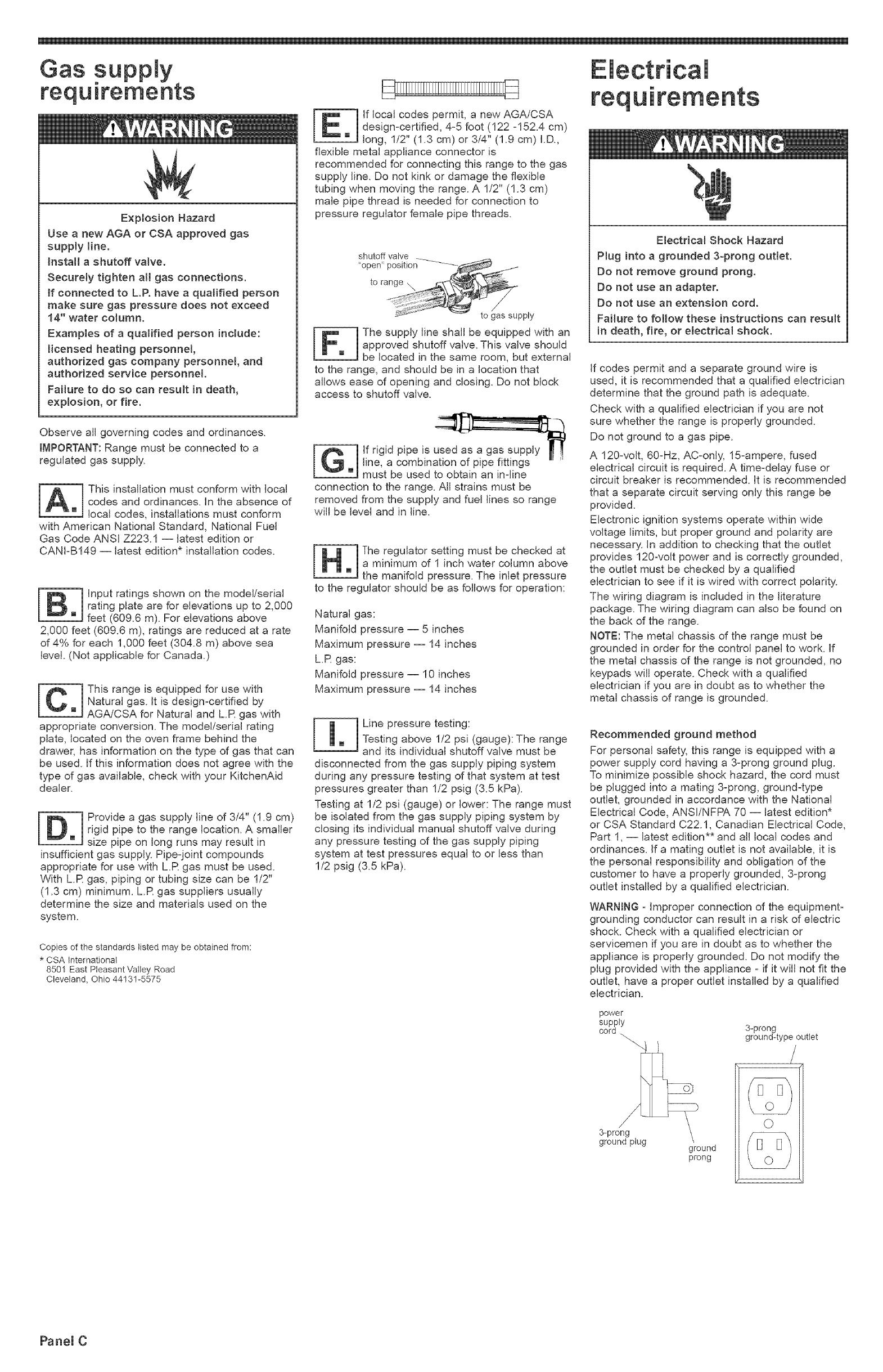
For personal safety, this range is equipped with a
power supply cord having a 3oprong ground plug.
To minimize possible shock hazard, the cord must
be plugged into a mating 3-prong, ground-type
outlet, grounded in accordance with the National
Electrical Code, ANSI/NFPA 70 -- latest edition*
or CSA Standard C22.1, Canadian Electrical Code,
Part 1, -- latest edition** and all local codes and
ordinances. If a mating outlet is not available, it is
the personal responsibility and obligation of the
customer to have a properly grounded, 3-prong
outlet installed by a qualified electrician.
WARNING - Improper connection of the equipment-
grounding conductor can result in a risk of electric
shock. Check with a qualified electrician or
servicemen if you are in doubt as to whether the
appliance is properly grounded. Do not modify the
plug provided with the appliance - if it will not fit the
outlet, have a proper outlet installed by a qualified
electrician.
power
suppty
cord 3-prong
"_ ground-type outlet
ground plug
ground
prong
O
Panel C
ow start...
W{th range in Htchen.
Put on safety glasses and gloves.
Remove shipping materials, tape and
protective film from range. Keep
cardboard bottom and shipping base under range.
Remove oven racks and parts package from inside
oven. If you have a slidezin range, remove back
vent package from range top. See Step 7 for
installation.
cardboard j_J--
corner
posts
Tip Over Hazard
A child or adult can tip the range and be
killed.
Connect antFtip bracket to rear range foot.
Reconnect the antFtip bracket, if the range
is moved.
Failure to follow these Bnstructions can
result Bndeath or serious burns to children
and adults.
.]
Line up holes in anti4ip bracket with mounting
holes in floor. Use the screws provided to fasten
anti-tip bracket to floor.
NOT[=:Anti4ip bracket must be mounted securely
to the sub41oor. Depending on the thickness of
your flooring, longer screws may be necessary to
anchor the bracket to the sub-floor. Longer screws
are available from your local hardware store.
Take 4 cardboard corner posts from the
carton. Stack one cardboard corner post
on top of another. Repeat with the other
two corner posts. Place corner posts lengthwise on
the floor in back of range so corner posts wilJ
support outer side edges of range as shown.
Excessive Weight Hazard
Use two or more people to move and install
range.
Failure to follow this instruction can result
in back or other injury.
Firmly grasp the range and gently lay it on
its back on the cardboard corner posts.
Pull cardboard bottom and shipping base
firmly to remove.
Use an adjustable wrench to loosen the
leveling legs 1_1/2 turns.
Place cardboard or hardboard in front of
range. Stand range back up onto
cardboard or hardboard.
Rear vent must
be installed.
\
\
If you have a slideqn range, remove the
outside screws from rear trim on range.
Use screws to attach rear vent to range.
Check that the type of gas supply is
correct for this range. (See model/serial
rating plate.)
If connecting to LR Gas, follow directions in
Conversion Kit included in your literature package.
If connecting to Natural gas, go to Step 9.
25" (63.5 cm)
countertop over
24" (61 cm)
cabinet
anti-tip
bracket
temptate
[_ lace the anti4ip bracket template on the
floor in the cabinet opening so that the
left edge is against cabinet and the top
edge is against the rear wall, molding or cabinet.
If countertop is deeper than 25 inches (63.5 cm),
measure and mark a distance 25 inches (63.5 cm)
in from front of countertop opening and align
template with mark (or subtract 25 inches
[63.5 cm] from the countertop depth and add the
difference to the corresponding dimension).
25" I
Countertop overhangs
_ cabinet side.
A = Difference between
countertop depth and 25"
(63.5 cm).
_A
anti-tip bracket
template
If countertop is not flush to the side of the cabinet
opening, align the left side of the template to allow
for the countertop overhang. Tape the freestanding
range anti-tip bracket template in place.
Contact a qualified floor covering installer for the
best procedure of drilling mounting holes through
your type floor covering.
Before moving, slide range onto cardboard or
hardboard.
To mount anti4ip bracket to wood floor,
use the anti-tip bracket template to
E mark where to drill mounting holes. Use
a drill with a 1/8" (0.3 cm) drill bit to drill the two
mounting holes. Remove template from floor.
To mount anti4ip bracket to concrete or ceramic
floor, use the anti4ip bracket template to mark
where to drill mounting holes. Use a drill with a
3/16" (0.5 cm) masonry drill bit to drill the two
holes. Remove template from floor. Tap plastic
anchors into mounting holes in floor with hammer.
Move range close to cabinet opening.
Remove cardboard or hardboard from
under range.
Press on front of storage drawer and
release to open. Pull open to first stop
position. Lift front of drawer to clear
white wheels in drawer guides. Remove drawer
and set it aside on a protected surface.
Carefully move range into final position.
Look under range (a flashlight may be
needed) to check that left rear leveling
leg is engaged in the anti-tip bracket. If leveling leg
is not properly engaged, remove and reposition the
anti-tip bracket to insure that the leveling leg fits
properly in the anti-tip bracket.
Place rack in oven. Place level on rack,
first side to side; then front to back. If
the range is not level, pull range
forward until the rear leveling leg is removed from
the anti-tip bracket. Adjust the leveling legs up or
down. Then slide range back into position. Check
that leveling leg is engaged in anti-tip bracket.
NOTE: Oven must be level for satisfactory baking
conditions.
PaneU D
All connections must be wrench-tightened.
etbow
pressure regulator
and valve assembly
flexible manual
connector shutoff valve
J
1/2" (I .3 cm) flare union adapters
1Assemble the flexible connector from
the gas supply pipe to the pressure
m regulator, located in the lower left side
of the storage drawer area, in this order: shutoff
valve, 1/2" (1.3 cm) flare union adapter, flexible
connector, 1/2" (1.3 cm) flare union adapter. Seal
all openings in floor or wall wherever range is
installed.
I Use pipe-joint compounds appropriate
for use with LR gas to seal all gas
m connections, if flexible connectors are
used, be certain connectors are not kinked.
j Open the shutoff valve in the gas
supply line. Wait a few minutes for the
m gas to move through the gas line.
ITest for gas leaks. Leak testing shall be
Iconducted according to the following
mJinstructions:
Test all connections by brushing on an approved
non-corrosive leak-detection solution. Bubbles will
show a leak. Correct any leak found.
Plug into a grounded 3 prong outlet.
B "8888" should appear in clock display.
I2 1 Remove vent cap, cooktop burner caps
ml and grates from parts package. Align
notches in burner caps with pins in
burner base. Burner caps should be level when
properly positioned. Place burner grates over
burners and caps. Place vent cap over vent dome.
vent
cap
er
vent _ grate
Adjust the height of top burner flames
(some models)
The cooktop LOW burner flame should be a steady
blue flame approximately 1/4" (0.64 cm) high. It
can be adjusted using the adjustment screw in the
center of the valve stem. The valve stem is located
directly underneath the control knob.
If the LOW flame needs to be adjusted:
a. Remove the control knob.
b. Hold the knob stem with a pair of pliers. Use
a small flat-head screwdriver to
turn the screw located in the
center of the control knob stem
until the flame is the proper
size.
c. Replace the control adjustment
knob. screw,
d. Test the flame by
turning the control from
"LO" to "HI", checking the
flame at each setting.
Top burner flame appearance:
towflame
high flame
I2 5 ] Remove the oven rack. Removethe
oven bottom and place it on a protected
m surface.
i2 6 ] Check the operation of the oven
burner. Push the "BAKE" pad and
m ,350oF, will appear in the temperature
display. Press the "START" pad. "LO" will appear in
the display; then "170°R ''The oven burner should
light in 50 to 60 seconds. This delay is normal. The
oven safety valve requires a certain time before it
will open and allow gas to flow.
Electric ignitors are used to light the oven and broil
burners.
Do not insert any object into the opening of the
protective shield that surrounds the ignitor.
Do not clean the area.
Push "CANCEL/OFF' pad. Insert oven
bottom tabs into slots in oven burner
area. Check that tabs are correctly
placed in slots. If the oven bottom is not positioned
properly, poor baking performance could occur.
Replace oven racks.
Check the operation of the
oven broil burner. Close the oven door.
Press the "BROIE' pad. "500 F' will
appear in the temperature display. Press the
"START" pad. The oven broil burner should light in
50 to 60 seconds. This delay is normal. The oven
safety valve requires a certain time before it will
open and allow gas to flow. The first time broil
burner is lighted, it may take longer to light
because of air in gas line. The first few times
burner is used sparks may appear. This is normal.
NOTE: Oven door must be shut for broil burner to
operate.
Look through oven window to check
broil burner for proper flame. The flame
should have a uniform, light blue
appearance around the burner surface. No yellow
tips, blowing or lifting of the flame should occur.
NOTE:The first few times the broil burner is used,
yellow sparks may appear in the flame. This is
normal and will stop after burner has been used a
few times.
Press the "CANCEL/OFF' pad. If the
broil burner flame needs adjustment,
contact your KitchenAid dealer or
authorized service company for assistance.
/
Insert storage drawer into slide rails
on sides of drawer opening. Lift front
of drawer slightly and push firmly to
close drawer.
E ectronic gnition System E
Initial lighting and gas flame adjustments.
Cooktop and oven burners use electronic ignitors
in place of standing pilots. When the cooktop
control knob is turned to the "LITE" position, the
system creates a spark to light the burner. This
sparking continues as long as the control knob is
turned to "LITE".
When the oven control is turned to the desired
setting, a glow bar heats up bright orange and
ignites the gas. No sparking occurs and the glow
bar remains on while the burners operate.
i Check the
operation of OFF
m the cooktop
burners. Pushinand _ {_
turn each control knob
to the "LITE" position.
The flame should light
within 4 seconds. The
first time a burner is _ ". _ )
lighted it may take "G,_ _-_'J'_
longer than 4 seconds ,'>-20 " _, _ , _ _o
to light because of air in @_D M_.o
gas line. LO
oven
rear
j ignitor
oven burner
I2 7 1 Check the oven burner for proper flame.
This flame should have a 1/2" (1.3 cm)
m long inner cone of bluish-green, with an
outer mantle of dark blue, and should be clean and
soft in character. No yellow tips, blowing or lifting of
flame should occur.
oven burner
air shutter
location \
air shutter -
locking screw rotate to
"-. adjust for
".. proper flame
as conversion
No attempt shall be made to convert the range
from the gas specified on the model/serial rating
plate for use with a different gas without consulting
the servicing gas supplier. An L.R Gas Conversion
Kit is included in your literature package.
To get the most efficient use from your new range,
read your Use and Care Guide. Keep Installation
Instructions and Guide close to range for easy
reference.
l lf burners do not light properly, turn
cooktop control knob to the "OFF"
m position. Check that the power supply
cord is plugged in and the circuit breaker or fuse
has not blown. Check that the gas shutoff valves
are set to the "OPEN" position. Repeat Step 22. If
a burner does not light at this point, contact your
KitchenAid dealer or authorized service company
for assistance.
brass orifice
oven burner hood (nut)
I28 ] If the oven flame needs be adjusted'
locate the air shutter near the center
m rear of range. Loosen the locking screw
and rotate the air shutter until the proper flame
appears. Tighten locking screw.
PaneU E
If range does not
operate...
Check that the circuit breaker is not tripped or the
house fuse is not blown.
Check that the power supply cord is plugged into
the wall receptacle.
Check that the gas supply is on.
Check that the regulator shutoff valve is in the
"OPEN" position.
For cleaning and
maintenance.,,
if removing the range is ever necessary for
cleaning or maintenance, shut off gas supply to
range. Disconnect the gas and electrical supply.
if the gas or electrical supply is inaccessible, lift
the range slightly at the front and pull the range out
away from the wall. Pull the range out only as far
as necessary to disconnect the gas and electrical
supply lines.
Remove the range to complete cleaning or
maintenance.
Move range back into operating position. Remove
drawer. Level the range. Connect gas line to range
and check for leaks. Plug in range or reconnect
power. Make sure that left rear leveling leg is
engaged in the anti-tip bracket.
If you need assistance...
The KitchenAid Consumer Assistance Center will
answer any questions about operating or
maintaining your range not covered in the
installation Instructions. The KitchenAid Customer
Interaction Center is open 24 hours a day, 7 days a
week. Just dial 1-800-422-1230 -- the call is free
within the continental United States.
When you call, you will need the range model
number and serial number. Both numbers can be
found on the model/serial rating plate located on
the oven frame behind the oven drawer.
Part No. 9755235 Rev. A
© 2004 KitchenAid.
® Registered Trademark of KitchenAid, U.S.A.
If you need service,,,
In the event that >,ourKitchenAid appliance should
need service, call the dealer from whom you
purchased the appliance or a KitchenAid-authorized
service company. A KitchenAid-authorized service
company is listed in the Yellow Pages of your
telephone directory under "Appliances -- Household
-- Major -- Service and Repair."
You can also obtain the service company's name
and telephone number by dialing, free, within the
continental United States, the KitchenAid Consumer
Assistance Center telephone number,
1-800-422-1230. A special operator will tell you the
name and number of your nearest KitchenAid-
authorized service company
Maintain the quality built into your KitchenAid appliance
-- call a KitchenAid-authorized service company.
Moving the range..,
Tip Over Hazard
A child or adult can tip the range and be
killed.
Connect anti=tip bracket to rear range foot.
Reconnect the anti=tip bracket, if the range
is moved.
Faiiure to foitow these instructions can
result in death or serious burns to chitdren
and adults.
HOME APPUANCES
Prepared by KitchenAid, Benton Harbor, Michigan 49022
When moving range, slide range onto cardboard or
hardboard to prevent damaging the floor covering.
If removing the range is necessary for cleaning or
maintenance:
1. Remove the storage drawer.
2. Shut off the gas supply to the range.
3. Slide range forward, away from the wall, just far
enough to disconnect the gas and electric supply
lines.
4. Slide range forward to complete cleaning or
maintenance.
5. Making sure the anti-tip bracket is installed:
Look for the anti-tip bracket securely attached
to floor.
Slide range back so rear range foot is under
anti-tip bracket.
6. Check that range is level.
7. Reconnect gas line to range and check for
leaks.
8. Plug power supply cord into outlet. Reinstall
storage drawer.
Printed in U.S.A.
04/2004
  • Page 1 1
  • Page 2 2
  • Page 3 3
  • Page 4 4
  • Page 5 5
  • Page 6 6
  • Page 7 7

KitchenAid 9755235 User manual

Category
Ovens
Type
User manual

Ask a question and I''ll find the answer in the document

Finding information in a document is now easier with AI