Tripp Lite 120V, 1000W PowerVerter APS Inverter/Charger with Pure Sine Wave Output Owner's manual
- Category
- Power adapters & inverters
- Type
- Owner's manual
This manual is also suitable for

1
Owner’s Manual
Sine Wave DC-to-AC Inverter/Chargers
Models: APS1012SW, APS2012SW
12VDC to 120VAC
1111 W. 35th Street, Chicago, IL 60609 USA
www.tripplite.com/support
Copyright © 2011 Tripp Lite. All rights reserved.
Warranty
Registration
Register online today for a
chance to win a FREE Tripp Lite
product! www.tripplite.com/warranty
Table of Contents
Important Safety Instructions 2
1. Overview & Features 3
1.1 Overview 3
1.2 Indicators, Controls and Settings 3
1.3 Optional Features 6
2. Battery Charger 6
2.1 Mode of Operation 6
2.2 Transfer Switching Speed 6
3. Battery Installation
and Maintenance 6
3.1 Select Battery Type 6
3.2 Monthly Maintenance 8
3.3 Battery Installation 8
3.4 Battery Connection 8
4. Inverter/Charger
Installation and Operation 10
4.1 Installation 10
4.2 Installation Diagrams and Charts 10
4.3 Installation and Start-Up 11
5. Technical Specifications 11
6. Troubleshooting 12
7. Service and
Warranty Registration 12
Español 13

2
Important Safety Instructions
SAVE THESE INSTRUCTIONS!
This manual contains important instructions and warnings that should be followed during the installation,
operation and storage of all Tripp Lite Inverter/Chargers.
Location Warnings
• Install your Inverter/Charger in a location or compartment that minimizes exposure to heat, dust, direct sunlight and
moisture. Flooding the unit with water will cause it to short circuit and could cause personal injury due to electric shock.
• Leave a minimum of 2” clearance at front and back of the Inverter/Charger for proper ventilation. To avoid overheating the
Inverter, any compartment that contains the Inverter/Charger must be properly ventilated with adequate outside air flow. The
heavier the load of connected equipment, the more heat will be generated by the unit.
• Do not install the Inverter/Charger directly near magnetic storage media, as this may result in data corruption.
• Do not install near ammable materials, fuel or chemicals.
• Do not mount unit with its front or rear panel facing down (at any angle). Mounting in this manner will seriously
inhibit the unit’s internal cooling, eventually causing product damage not covered under warranty.
Battery Connection Warnings
• Multiple battery systems must be comprised of batteries of identical voltage, age, amp-hour capacity and type.
• Because explosive hydrogen gas can accumulate near batteries if they are not kept well-ventilated, do not install batteries in
a “dead air” compartment. Ideally, any compartment would have some ventilation to outside air.
• Sparks may result during nal battery connection. Always observe proper polarity as batteries are connected.
• Do not allow objects to contact the DC input terminals. Do not short or bridge these terminals together. Serious personal
injury or property damage could result.
Ground Connection Warnings
• Safe operation requires connecting the Inverter/Charger’s Main Ground Terminal directly to the frame of the vehicle or earth
ground.
Equipment Connection Warnings
• Use of this equipment in life support applications where failure of this equipment can reasonably be expected to cause
the failure of the life support equipment or to signicantly affect its safety or effectiveness is not recommended. Do not
use this equipment in the presence of a ammable anesthetic mixture with air, oxygen or nitrous oxide.
• You may experience uneven performance results if you connect a surge suppressor, line conditioner or UPS system to the
output of the Inverter/Charger.
• User must supply proper protection for wire openings in unit panels.
Operation Warnings
• Your Inverter does not require routine maintenance.
• Potentially lethal voltages exist within the Inverter/Charger as long as the battery supply is connected. During any service
work, the battery supply should therefore be disconnected.
• Do not connect or disconnect batteries while the Inverter/Charger is operating from the battery supply. Dangerous arcing may
result.

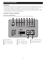
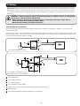
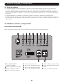
321 4 5 6 7 8 9
10 11
3
1. Overview and Features
1.1 Overview
• Tripp Lite’s Sine Wave Inverter-Charger is a heavy-duty unit generating a pure sine wave from a 12V battery bank. It can
supply energy to a wide range of connected equipment; from heaters, air conditioners, refrigerators and vacuum cleaners to
computers and peripheral devices. It is designed to work in heavy load conditions, so de-rating is unnecessary.
• The smart charger is compatible with various battery types and sizes. The switch module automatically diverts the energy
transfer path between the inverter and an AC input. When the AC source is lower than the transfer level, the path switches
to the inverter. Otherwise, the load is powered by the AC input.
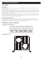
1.2 Indicators, Controls and Settings
1.2.1 Controls and LED Indicators
Shown below are the control panel and indicator lights on the front panel of the Inverter/Charger.
1
Power ON/OFF Button
2
LED 1 – DC Mode Inverter
3
LED 2 – AC Mode Charger
4
LED 3 – Inverter Condition
5
LED 4 – Battery Limits
6
LED 5 – 25% Battery Voltage
7
LED 6 – 50% Battery Voltage
8
LED 7 – 75% Battery Voltage
9
LED 8 – 100% Battery Voltage
10
Battery Temperature Port (RJ11)
11
Communication Port (RJ45)

4
1. Overview and Features
LED and Alarm Indicator
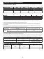
LED 1 LED 2 LED 3 LED 4 LED 5 LED 6 LED 7 LED 8 Alarm
AC Normal Off
On/
Flashing
Off Off 10.8V~11.5V 11.5 ~ 12.5V 12.5 ~ 13.5V >13.5V Off
DC Mode On Off Off Off 10.2 ~ 11.5V 11.5 ~ 12.5V 12.5 ~ 13.0V >13.0V Off
Battery Low
(DC Mode)
On Off Off On 10.2 ~ 11.5V 11.5 ~ 12.5V 12.5 ~ 13.0V >13.0V
1 beep
@ 5 sec for
3 min.
Low Battery
Cutoff (LBCO)
Off Off Off On Off Off Off Off
1 beep @
shutdown
Battery High
(AC Mode)
On Off Off Flashing 10.2 ~ 11.5V 11.5 ~ 12.5V 12.5 ~ 13.0V >13.0V
1 beep
@ 0.5sec
Overload—
110%-129%
(DC Mode)
On Off On Off 10.2 ~ 11.5V 11.5 ~ 12.5V 12.5 ~ 13.0V >13.0V
1 beep
@ 0.5 sec
Overload—
130%-149%
(DC Mode)
On Off On Off 10.2 ~ 11.5V 11.5 ~ 12.5V 12.5 ~ 13.0V >13.0V
On
(Constant)
Overload—
>150%
(DC Mode)
On Off On Off 10.2 ~ 11.5V 11.5 ~ 12.5V 12.5 ~ 13.0V >13.0V
On
(Constant)
AC Bypass
Power Off
Off Off Off Off 10.8 ~ 11.5V 11.5 ~ 12.5V 12.5 ~ 13.5V >13.5V Off
1.2.2 Power ON/OFF Button
The Power ON/OFF button is located in the left of the panel. Press to power the Inverter/Charger ON or OFF. When the button is
pressed, the alarm will beep.
Note: When connected to batteries, the Inverter/Charger will start up even if not connected to AC power. Defaults to 60Hz.
Note: Unit is in BYPASS mode as soon as power is applied to the input.
Power On: Press the Power ON/OFF button for 3 seconds until the alarm beeps and the INVERTER MODE light illuminates.
Power Off: Press the Power ON/OFF button for 3 seconds. The alarm will beep when the shutdown process is completed.
1.2.3 DC Mode Inverter (LED 1)
This LED illuminates to indicate that the system is working in inverter mode (supplying power from battery).
1.2.4 AC Mode Charger (LED 2)
The LED flashes during the charging process and remains illuminated once the battery is full charged.
1.2.5 Inverter Condition (LED 3)
When the inverter temperature exceeds the default setting, this LED will ash and the inverter will shut down automatically.
After the temperature returns to normal, depress the Power ON/OFF button to restart.
When the unit is overloaded in DC mode, LEDs 1, 3 and the audible alarm indicate inverter status as follows:
Load Capacity (DC Mode) LED1 LED 3 Alarm INVERTER STATUS
110%-129% On On 1 beep/0.5sec Shutdown after 60 seconds.
130%-149% On On On (Constant) Shutdown after 10 seconds.
>150% On On On (Constant) Shutdown after 1 second.
1.2.6 Battery Limits (LED 4)
Battery High: In AC mode, LED 4 will flash.
Battery Low: LED 4 will illuminate and the alarm will beep once every ve seconds for three minutes. If the battery voltage
drops below the cutoff voltage (LBCO), then the inverter will shut down all LEDs except LED4, and will turn off.

5
1. Overview and Features
1.2.7 Battery Voltage (LED 5-8)
LED 5-8 indicate the battery capacity as detailed in the following table:
Battery Voltage LED 5 LED 6 LED 7 LED 8
25% On — — —
50% On On — —
75% On On On —
100% On On On On
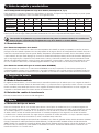
1.2.8 Voltage Setting (Switch 1-3)*
Switch ON OFF
DC-to-AC Transfer Delay (Switch 1) 30 sec (Default) 5 sec
Low Battery Alarm (Switch 2) 11.2V 10.9V (Default)
AC Transfer Voltage (Switch 3) 95V 85V (Default)
*Note:
1. Switch 1 is located farthest from the battery temperature port. See diagram on page 3.
2. All switches must be set before the system is turned on.
3. Switch 2 sets the low battery voltage alarm level (at higher voltage, the alarm sounds sooner).
4. Switch 3: Low-level AC-to-DC voltage point. If the AC input voltage decreases to below the setpoint, the inverter will
automatically switch to DC MODE. Please see the table for details.
Nominal Voltage Low Voltage Transfer Point (AC-to-DC) Return Voltage Point (DC-to-AC)
120V
On 95 100
Off 85 90
1.2.9 Search Mode Setting (Switch 4)
Search Mode activates when the unit is operating in inverter mode (battery power) to prevent unnecessary battery discharge
when electrical power is not required. If the inverter is supporting loads that must constantly be powered, turn off switch 4 to
disable Search Mode.
Switch 4 Search Mode Function
ON Enable Inverter only turns on if load > 100W
OFF (Default) Disable
Inverter is always on in the absence of
AC power
1.2.10 Battery Type/Floating Voltage (Switch 5)
Switch 5 Floating Voltage Acceptance Voltage Battery Type
ON (Default) 13.8V 14.5V Absorbed Glass Mat (AGM)
OFF 13.2V 13.8V Wet-Cell
Note: The unit will charge the battery to Acceptance voltage, continue for up to 12 hours, then drop to Floating voltage.

6
1. Overview and Features
1.2.11 Battery Charging Rate Setting (Switch 6, 7 & 8)
These switches control the maximum charging rate in amps. The charge rate has 8 stages. It can be adjusted by setting these
switches as shown in the following table:
Switch 6
ON ON ON ON OFF OFF OFF OFF
Switch 7
ON ON OFF OFF ON ON OFF OFF
Switch 8
ON OFF ON OFF ON OFF ON OFF
APS1012SW
40A 32A 24A 20A (Default) 16A 12A 8A 4A
APS2012SW
60A 48A 36A 30A (Default) 24A 18A 12A 6A
Note: The charging rate depends on the battery bank size. Consult the battery manufacturer’s specs for the maximum allowed
charge rate (usually 0.3 times the AH rating).
Caution! An excessively high charging rate can overheat the battery. If a small-capacity battery is
used, set the battery charge rate to the minimum setting.
1.3 Features
1.3.1 Battery Temperature Port
This port allows connection of a Battery Temperature-Sensing Cable (sold separately). The sensing function prolongs battery
life by adjusting the charge oat voltage level based on battery temperature. Connect the sensor cable to the RJ11 port
labeled “Battery Temperature.” With user-supplied electrical or duct tape, secure the sensor to the side of the battery below
the electrolyte level. Make sure that nothing, not even tape, comes between the sensor and the side of the battery. To guard
against false readings due to ambient temperature, place the sensor between batteries, if possible, or away from the sources
of extreme heat or cold. If the sensor cable is not used, the Inverter/Charger will charge according to its default 25°C values.
1.3.2 Communication Port (for APSRMSW Remote Control)
This port allows connection with the APSRMSW Remote Control (sold separately). The remote conrol allows the Inverter/
Charger to be mounted in a compartment or cabinet out of sight, while operated conveniently from a remote location. See
instructions packed with the remote control module for more information.
2. Battery Charger
2.1 Mode of Operation
The internal battery charger and automatic transfer relay allow the unit to operate as either a battery charger or an inverter. An
external source of AC power (e.g., shore power or generator) must be supplied to the inverter’s AC input in order to allow it to
operate as a battery charger. When the unit is operating as a charger, AC loads are powered by the external AC power source.
2.2 Transfer Switching Speed
Transfer time is less than 16 milliseconds.
3. Battery
3.1 Select Battery Type
Select 12V “Deep Cycle” batteries to receive optimum performance from your Inverter/Charger. Do not use ordinary car or
starting batteries or batteries rated in Cold Cranking Amps (CCA). If the batteries you connect to the Inverter/Charger are not
true Deep Cycle batteries, their operational lifetimes may be signicantly shortened. If you are using the same battery bank to
power the Inverter/Charger as well as DC loads, your battery bank will need to be appropriately sized (larger loads will require a
battery bank with a larger amp-hour capacity) or the operational lifetimes of the batteries may be signicantly shortened.
Batteries of either Wet-Cell (vented) or Gel-Cell /Absorbed Glass Mat (sealed) construction are ideal. Set Switch 5 to OFF
for Wet-Cell batteries and to ON for Absorbed Glass Mat (AGM) batteries. Two 6-volt “golf cart”, Marine Deep-Cycle or 8D
Deep-Cycle batteries in series are also acceptable. In many cases, the vehicle battery may be the only one installed. Auxiliary
batteries must be identical to the vehicle batteries if they are connected to each other.

7
540 watts ÷ 12V = 45 DC Amps
270 Amp-Hours ÷ 55 Amps
Inverter/Charger Rating = 5 Hours Recharge
Example
Tools
¼” Drill Orbital Sander Cordless Tool Charger
Appliances
Blender Color TV Laptop Computer
300W + 220W + 20W = 540W
300W + 140W + 100W = 540W
45 DC Amps × 5 Hrs. Runtime
× 1.2 Inefficiency Rating = 270 Amp-Hours
•STEP1:DetermineTotalWattageRequired
Add the wattage ratings of all equipment you will connect to your
Inverter/Charger. Wattage ratings are usually listed in equipment
manuals or on nameplates. If your equipment is rated in amps,
multiply that number times AC utility voltage to determine watts.
(Example: a ¼ in. drill requires 2½ amps. 2½ amps × 120 volts =
300 watts .)
Note: Your Inverter/Charger will operate at higher efficiencies at about 75% - 80% of
nameplate rating.
•STEP2:DetermineDCBatteryAmpsRequired
Divide the total wattage required (from step 1, above) by the battery
voltage (12) to determine the DC amps required.
•STEP3:EstimateBatteryAmp-HoursRequired
(for operation unsupported by the alternator)
Multiply the DC amps required (from step 2, above) by the number
of hours you estimate you will operate your equipment exclusively
from battery power before you have to recharge your batteries with
utility- or generator-supplied AC power. Compensate for inefciency by
multiplying this number by 1.2. This will give you a rough estimate of
how many amp-hours of battery power (from one or several batteries)
you should connect to your Inverter/Charger.
NOTE! Battery amp-hour ratings are usually given for a 20-hour discharge rate.
Actual amp-hour capacities are less when batteries are discharged at faster rates.
For example, batteries discharged in 55 minutes provide only 50% of their listed amp-
hour ratings, while batteries discharged in 9 minutes provide as little as 30% of their
amp-hour ratings.
•STEP4:EstimateBatteryRechargeRequired,
Given Your Application
You must allow your batteries to recharge long enough to replace the
charge lost during inverter operation or else you will eventually run
down your batteries. To estimate the minimum amount of time you
need to recharge your batteries given your application, divide your
required battery amp-hours (from step 3, above) by your Inverter/
Charger’s rated charging amps (depending on the Switch 6, 7 and 8
ON/OFF settings).
NOTE! For Tripp Lite Inverter/Chargers providing 1000 watts or less of continuous AC
power, a full-size battery will normally allow sufficient power for many applications
before recharging is necessary. For mobile applications, if a single battery is
continuously fed by an alternator at high idle or faster, then recharging from utility or
generator power may not be necessary. For Tripp Lite Inverter/Chargers over 1000 watts
used in mobile applications, Tripp Lite recommends you use at least two batteries, if
possible fed by a heavy-duty alternator anytime the vehicle is running. Tripp Lite Inverter/
Chargers will provide adequate power for ordinary usage within limited times without
the assistance of utility or generator power. However, when operating extremely heavy
electrical loads at their peak in the absence of utility power, you may wish to “assist
your batteries” by running an auxiliary generator or vehicle engine, and doing so at
faster than normal idling.
3. Battery
3.1.1 Match Battery Amp-Hour Capacity to Your Application
Select a battery or system of batteries that will provide your Inverter/Charger with proper DC voltage and an adequate amp-
hour capacity to power your application. Even though Tripp Lite Inverter/Chargers are highly-efcient at DC-to-AC inversion,
their rated output capacities are limited by the total amp-hour capacity of connected batteries and the support of your
vehicle’s alternator if the engine is kept running.

8
3. Battery
3.2 Monthly Maintenance
• Check the level of the electrolyte of each Wet-Cell battery cell monthly after the batteries have been charged. It should be
about one-half inch above the top of the plates, but not completely full. Note: This is not necessary on maintenance-free
batteries.
• Check the battery connections for tightness and corrosion. If any corrosion is found, disconnect the cables and clean them
with a mild solution of baking soda and water. DO NOT ALLOW THE SOLUTION TO ENTER THE BATTERY. When nished, rinse
the top of the battery with clean water.
• To reduce corrosion on the battery terminals, coat them with a thin layer of petroleum jelly or anti-corrosion grease. Do not
apply any material between the terminal and the cable lugs; the connection should be metal to metal. Apply the protective
material after the bolts have been tightened.
3.3 Battery Installation
Caution! Batteries can produce extremely high currents. Review both the important safety
instructions at the beginning of this manual and the battery supplier’s precautions before installing
the inverter and batteries.
3.3.1 Battery Location
Batteries should be installed in an accessible location with good access to the battery caps and terminals. At least two feet
(24 in.) of overhead clearance is recommended. They must be located as close as possible to the inverter. Do not locate the
inverter in the same compartment with non-sealed batteries (sealed batteries are acceptable). The gasses produced by these
batteries during charging are very corrosive and will shorten the life of the inverter.
3.3.2 Battery Enclosure
Batteries should be installed in a ventilated, locked enclosure or room. The enclosure should be well-ventilated to prevent
accumulation of hydrogen gasses that are released in the battery charging process. The enclosure should be made of acid
resistant material or coated with an acid resistant nish to resist corrosion from spilled electrolyte and released fumes. If the
batteries are located outdoors, the enclosure should be rainproof and have mesh screens to prevent insects and rodents from
entering. Before placing the batteries in the enclosure, cover the bottom with a layer of baking soda to neutralize any acid
spills.
3.4 Battery Connection
3.4.1 Connect your Inverter/Charger to your batteries using the following procedures:
• Connect DC Wiring: Though your Inverter/Charger is a high-efciency converter of electricity, its rated output capacity is
limited by the length and gauge of the cabling running from the battery to the unit. Use the shortest length and largest
diameter cabling to provide maximum performance (see table below). Shorter and heavier gauge cabling reduces DC
voltage drop and allows for maximum transfer of current. Your Inverter/Charger is capable of delivering peak wattage at
up to 200% of its rated continuous wattage output for brief periods of time. Heavier gauge cabling should be used when
continuously operating heavy draw equipment under these conditions. Tighten your Inverter/Charger and battery terminals
to approximately 3.5 Newton-meters of torque to create an efcient connection and to prevent excessive heating at this
connection. Insufcient tightening of the terminals could void your warranty.
Maximum Recommended DC Cable Length
Maximum Distance From Battery to Inverter/
Charger
Output
Wire Gauge (AWG)
2 0 00 (2/0)
1000W 20 ft. 31 ft. 39 ft.
2000W
Do not use Do not use
20 ft.

12 Volt Inverter/Charger
12 Volts
12 Volts
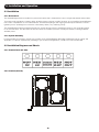
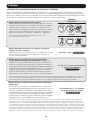
12 Volt Main Battery Connection
12 Volt Inverter/Charger
12 Volts
12 Volts
12 Volts
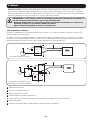
12 Volt Main and Auxiliary (House)
Battery Connection (Isolated Parallel)
1 2
3
3
4
7
7
5
1
6
2
2
5
9
1
12 Volt Alternator
2
Vehicle Battery Ground
3
12 Volt Main Battery
4
12 Volt Auxiliary (House) Battery
5
UL-Listed Fuse & Fuse Block (mounted within 18 inches of the battery)
6
Battery Isolator
7
Large Diameter Cabling, Maximum 2/0 Gauge to Fit Terminals
3. Battery
• Connect Fuse: NEC (National Electrical Code) article 551 requires that you connect all of your Inverter/Charger’s positive
DC Terminals directly to a UL-listed fuse(s) and fuse block(s) within 18 inches of the battery. The fuse’s rating must equal
or exceed the minimum DC fuse rating displayed on the Inverter/Charger’s nameplate. See diagrams below for proper fuse
placement.
WARNING! • Failure to properly ground your Inverter/Charger to a vehicle’s chassis or earth ground
may result in a lethal electrical shock hazard.
• Never attempt to operate your Inverter/Charger by connecting it directly to output from an
alternator rather than a battery or battery bank.
• Observe proper polarity with all DC connections.
3.4.2 Non-Vehicular or Vehicular
Your Inverter/Charger’s Nominal DC Input Voltage must match the voltage of your battery or batteries—12 Volts in most
vehicular applications.
It is possible to connect your Inverter/Charger to the main battery within your vehicle’s electrical system. In most vehicles, the
Inverter/ Charger will be connected to one or more dedicated auxiliary (house) batteries that are isolated from the drive system
to prevent possible draining of the main battery.

10
4. Installation and Operation
4.1 Installation
4.1.1 Environment
The Inverter/Charger must be installed in a protected location that is isolated from sources of high temperature and moisture.
To promote peak performance, battery cables should be kept as short as possible. However, do not install the Inverter/Charger
in the same compartment as non-sealed batteries. Accumulated hydrogen and oxygen generated by the batteries could be
ignited by an arc (resulting from connection of the battery cables) or by switching a relay.
The Inverter/Charger requires unrestricted air flow to operate at high power for sustained periods. Do not mount the inverter
in an enclosed space. This will restrict air ow and cause the inverter’s protection circuitry will activate, reducing maximum
available power.
4.1.2 System Grounding
Proper grounding is essential to assure safe operation of the Inverter/Charger. Grounding requirements vary in country and
application. For specic requirements pertaining to your location and application, consult local codes and the NEC.
4.2 Installation Diagrams and Charts
4.2.1 Terminal Block (AC Side)
4.2.2 Terminal (DC Side)4. Installation and Operation

11
4. Installation and Operation
4.3 Installation and Start-Up
4.3.1
Connect the unit to the batteries per Section 3. Ensure that the nominal DC battery voltage is 12V.
4.3.2
Connect the unit to the AC load. Then, connect to the AC source. Conrm all wiring is correct and terminal is tight.
4.3.3
Press the ON/OFF button. The system will start working after a few seconds. If the AC source power fails, the unit will work in
Inverter mode. Otherwise, the system will switch to AC Mode and will power the load while charging the battery.
5. Technical Specifications
Model
Specification
APS1012SW APS2012SW
Continuous Power 1000 Watts 2000 Watts
Peak Inverter Efciency >79%
Output Waveform Sine Wave
DC Current at Rated Power 120 Amps 250 Amps
Recommended Battery Fuse 200 Amps 400 Amps
Nominal Input Voltage 12 VDC
DC Input Voltage Range 10.0 ~ 16 VDC
Low Battery Protection (Heavy/Light Load) 10.9/11.2 VDC
DC Mode Output Voltage Regulation +/- 10%
Power Factor Allowed 0.8 to 1
Frequency Regulation 50/60 Hz +/- 0.5 Hz (Autoselect)
Standard Output Voltage 120 VAC
Load Sensing (Power Saving) 100 W
Transfer Time 16 ms, maximum
Forced Air Cooling Variable Speed
Automatic Transfer Relay 15A 30A
Adjustable Charge current 4 ~ 40 A 6 ~ 60A
Resistive Load 100%
Inductive Load YES
Motor Load YES
Rectier Load YES
Wall-Mounting YES

12
6. Troubleshooting
• Your Inverter/Charger requires no maintenance and contains no user-serviceable or user-replaceable parts, but should be
kept dry at all times. Periodically check, clean and tighten all cable connections, as necessary, both at the unit and at the
battery.
• A small-size battery being charged at a higher charging rate could cause an overvoltage shutdown. To prevent this, reduce
the charge rate or discharge the battery before recharging.
• If the Inverter does not start up properly, disconnect the system from the battery for 30 seconds, and then repeat the
startup procedure. If the system still does not start up properly, visit www.tripplite.com/support.
201110125 • 933053-EN
1111 W. 35th Street, Chicago, IL 60609 USA
www.tripplite.com/support
WARRANTY REGISTRATION
Visit www.tripplite.com/warranty today to register the warranty for your new Tripp Lite product. You’ll be automatically entered into a drawing
for a chance to win a FREE Tripp Lite product!*
* No purchase necessary. Void where prohibited. Some restrictions apply. See website for details.
Regulatory Compliance Identification Numbers
For the purpose of regulatory compliance certications and identication, your Tripp Lite product has been assigned a unique series
number. The series number can be found on the product nameplate label, along with all required approval markings and information. When
requesting compliance information for this product, always refer to the series number. The series number should not be confused with the
marking name or model number of the product.
Tripp Lite follows a policy of continuous improvement. Product specications are subject to change without notice.
7. Service
Your Tripp Lite product is covered by the warranty described in this manual. A variety of Extended Warranty and On-Site Service
Programs are also available from Tripp Lite. For more information on service, visit www.tripplite.com/support. Before returning
your product for service, follow these steps:
1. Review the installation and operation procedures in this manual to insure that the service problem does not originate from a
misreading of the instructions.
2. If the problem continues, do not contact or return the product to the dealer. Instead, visit www.tripplite.com/support.
3. If the problem requires service, visit www.tripplite.com/support and click the Product Returns link. From here you can
request a Returned Material Authorization (RMA) number, which is required for service. This simple on-line form will ask
for your unit’s model and serial numbers, along with other general purchaser information. The RMA number, along with
shipping instructions will be emailed to you. Any damages (direct, indirect, special or consequential) to the product incurred
during shipment to Tripp Lite or an authorized Tripp Lite service center is not covered under warranty. Products shipped to
Tripp Lite or an authorized Tripp Lite service center must have transportation charges prepaid. Mark the RMA number on the
outside of the package. If the product is within its warranty period, enclose a copy of your sales receipt. Return the product
for service using an insured carrier to the address given to you when you request the RMA.
Page is loading ...
Page is loading ...
Page is loading ...
Page is loading ...
Page is loading ...
Page is loading ...
Page is loading ...
Page is loading ...
Page is loading ...
Page is loading ...
Page is loading ...
Page is loading ...
-
 1
1
-
 2
2
-
 3
3
-
 4
4
-
 5
5
-
 6
6
-
 7
7
-
 8
8
-
 9
9
-
 10
10
-
 11
11
-
 12
12
-
 13
13
-
 14
14
-
 15
15
-
 16
16
-
 17
17
-
 18
18
-
 19
19
-
 20
20
-
 21
21
-
 22
22
-
 23
23
-
 24
24


Tripp Lite 120V, 1000W PowerVerter APS Inverter/Charger with Pure Sine Wave Output Owner's manual
- Category
- Power adapters & inverters
- Type
- Owner's manual
- This manual is also suitable for
Ask a question and I''ll find the answer in the document
Finding information in a document is now easier with AI
in other languages
Related papers
-
Tripp Lite APSX2012SW User manual
-
Tripp Lite PowerVerter APS700HF User manual
-
-
-
-
-
-
-
-
Other documents
-
Creative Inspire T10 Quick start guide
-
PEAK PKC0AW Owner's manual
-
-
Schumacher PI-140PI-140 Owner's manual
-
DieHard 71496 Owner's manual
-
Clore Automotive PI15000X User manual
-
 TECO-Westinghouse TECO-Westinghouse E510 Compact AC Drives User guide
-
Jupiter 57334 Owner's manual
-
 Xantrex M1512 (E) and M1524 (E) Owner's manual
-
Schumacher Electric XI14 Owner's manual

