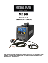
Clarke IMAGE 14 120V Operating instructions

Category
Vacuum cleaners
Type
Operating instructions

This manual is also suitable for

120v FLUXCORE/MIG SPOOL GUN WELDER
OPERATING MANUAL
CAUTION: Before using this
product, read this manual and
follow all its Safety Rules and
Operating Instructions.
Model # WE6441
UPC: 052249 065371
Clarke Power Products Inc.
28740 Glenwood Rd., Perrysburg, OH 43551
Tel # 800-227-9603 or (419) 930-2299 • Fax # (419) 930-0740
www.clarkeusa.com • E-mail: customer[email protected]
Limited Warranty on Clarke Welder
This Clarke welder has a limited warranty covering manufacturing defects. Even though we have
strict quality control during our manufacturing process, sometimes a product gets shipped that does not
meet our specifications. If you have a product that does not work correctly within 30 days of your pur-
chase, take the product and the original receipt to the store for credit or replacement. After 30 days, please
do not return the product to the store. This will only delay the repair process.
For ten years from the date of purchase, if the welder's transformer or rectifier fails, due to a defect
in material or workmanship, you must return the complete welder to the address below or to an authorized
repair center - postage or UPS paid - for repair or replacement of the defective part.
For two years from the date of purchase, if any part of this welder, outside of the transformer or
rectifier, fails due to a defect in material or workmanship, you must return the complete welder to the
address below or to an authorized repair center - postage or UPS paid - for repair or replacement of the
defective part.
This warranty does not cover normal wear and tear or consumable parts such as contact tips or noz-
zles, which are consumed during normal welder operation. This warranty applies only while this product is
used in the United States or Canada. This warranty gives you specific legal rights, and you may also have
other rights, which vary from state to state.
Before returning any product, you must contact the Customer Service Department of Clarke Power
Products at 1-800-227-9603 to acquire a Return Authorization Number.
When sending your product you must pack it securely and include:
1. A copy of the dated store receipt showing the original purchase,
2. Full name and address where product was purchased,
3. Your full name, street address and telephone number.
4. Your Return Authorization Number, clearly marked on outside of package.
Clarke Power Products will not be responsible for any damage caused in shipment of your product. Clarke
strongly suggests that you insure your product shipment.
Ship to:Clarke Power Products Inc., 28740 Glenwood Rd, Perrysburg, OH 43551,
A
TTN: Warranty Return
W
e will examine the product. If the problem is due to a manufacturing defect and within our warranty peri
-
od, we will repair or replace the product at no charge and return it to you - postage or UPS paid. If the
problem is due to misuse, abuse, the product has been modified or out of warranty, we will contact you
with a repair estimate and ask for a credit card number for payment.
After the product has been repaired, it
will be returned postage or UPS paid.
2
WARRANTY
TABLE OF CONTENTS
Warranty ..................................................2
Safety Summary......................................3
Safety Information..................................3
Shock Hazards ......................................4
Flash Hazards........................................4
Fire Hazards ..........................................5
Fume Hazards ......................................6
Compressed Gasses
and Equipment Hazards......................6
Additional Safety Information ................7
Welder Specifications ............................8
Description ............................................8
Welder Operating Characteristics..........8
Duty Cycle ..........................................8
Internal Thermal Protection ..................8
Know Your Welder ..................................9
Welder Installation ..................................10
Site Selection ........................................10
Power Source Connection ....................10
Assembling the W
elder..........................10
Packing List............................................10
Selecting Shielding Gas ........................12
Install
The Shielding Gas ......................13
Check the Gas Flow ..............................13
Align and Set the Drive Roller ..............13
Install the Welding Wire ........................14
Set the Wire Drive Tension ....................16
Change Polarity ....................................16
Operation ................................................18
Controls and Indicators..........................18
Tuning in the Wire Speed ......................18
Learning to Weld....................................19
Holding the Gun ....................................19
Welding Techniques ..............................20
Moving the Gun ..................................20
Types of Weld Beads ..........................20
Welding Positions ................................21
Multiple Pass Welding ........................22
Special Welding Methods....................23
Spot Welding ....................................23
Maintenance ............................................24
General ..................................................24
Consumable Maintenance ....................24
Maintaining the Contact Tip ..................24
Maintaining the Nozzle ..........................24
Testing for a Shorted Nozzle ................25
Preventive Maintenance ........................25
Troubleshooting ....................................26
Wiring Diagram........................................27
Parts List..................................................28
3
TABLE OF CONTENTS
The warnings, cautions and instructions dis-
cussed in this instruction manual cannot
cover all possible conditions or situations
that could occur. It must be understood by
the operator that common sense and caution
are factors which cannot be built into this
product, but must be supplied by the opera-
tor. Reading this operator’s manual before
using the welder will enable you to do a bet-
ter, safer job. Learn the welder’s applications
and limitations as well as the specific
potential hazards peculiar to welding.
IMPORTANT SAFETY
INFORMATION
The following safety information is provided
as guidelines to help you operate your new
welder under the safest possible conditions.
Any equipment that uses electrical power
can be potentially dangerous to use when
safety or safe handling instructions are not
known or not followed. The following safety
information is provided to give the user the
information necessary for safe use and
operation.
A procedure step preceded by a
WARNING is an indication that the next step
contains a procedure that might be injurious
to a person if proper safety precautions are
not heeded.
A procedure step preceded by a
CAUTION
is an indication that the next step contains a
procedure that might damage the equipment
being used.
A
NOTE may be used before or after a
procedure step to highlight or explain
something in that step.
READ ALL SAFETY INSTRUCTIONS
CAREFULLY
before attempting to install,
operate, or service this welder
. Failure to
comply with these instructions could result in
personal injury and/or property damage.
RETAIN THESE INSTRUCTIONS FOR
FUTURE REFERENCE.
Note:
The following safety alert symbols identify
important safety messages in this manual.
When you see one of the symbols shown
here, be alert to the possibility of personal
injury and carefully read the message that
follows.
This symbol indicates that the
possibility of electric shock hazard
exists during the operation of the
step(s) that follow.
This symbol indicates that the
possibility of fire hazard exists
during the operation of the step(s)
that follow.
This symbol indicates that the
helmet must be worn during the
step(s) that follow to protect
against eye damage and burns
due to flash hazard.
This symbol indicates that the
possibility of toxic gas hazard
exists during operation of the
step(s) that follow.
This symbol indicates that the
possibility of being burned by hot
slag exists during operation of the
step(s) that follow.
This symbol indicates that the eye
protection should be worn to
protect against flying debris in
the following step(s).
This symbol indicates that the
possibility of injury or death exists
due to improper handling and
maintenance of compressed gas
cylinders or regulators.
Published standards on safety are
available. They are listed in ADDITIONAL
SAFETY INFORMATION at the end of
this SAFETY
SUMMAR
Y.
The National Electrical Code, Occupation
Safety and Health Act regulations, local
industrial codes and local inspection
requirements also provide a basis for
equipment installation, use, and service.
SAFETY SUMMARY
4
SHOCK HAZARD
WARNING
ELECTRIC SHOCK CAN KILL! To reduce
the risk of death or serious injury from shock,
read, understand, and follow the following
safety instructions. In addition, make certain
that anyone else who uses this welding
equipment, or who is a bystander in the
welding area understands and follows these
safety instructions as well.
IMPORTANT! TO REDUCE THE RISK
OF DEATH, INJURY, OR PROPERTY
DAMAGE, DO NOT ATTEMPT
OPERATION of this welding equipment
until you have read and understand the
following safety summary.
Do not, in any manner, come into
physical contact with any part of the
welding current circuit. The welding
current circuit includes:
a. the work piece or any conductive
material in contact with it,
b. the ground clamp,
c. the electrode or welding wire,
d. any metal parts on the electrode
holder, or wire feed gun.
Do not weld in a damp area or come in
contact with a moist or wet surface.
Do not attempt to weld if any part of
clothing or body is wet.
Do not allow the welding equipment to
come in contact with water or moisture.
Do not drag welding cables, wire feed
gun, or welder power cord through or
allow them to come into contact with
water or moisture.
Do not touch welder, attempt to turn
welder on or off if any part of the body or
clothing is moist or if you are in physical
contact with water or moisture.
Do not attempt to plug the welder into the
power source if any part of body or cloth-
ing is moist, or if you are in physical
contact with water or moisture.
Do not connect welder work piece clamp
to or weld on electrical conduit.
Do not alter power cord or power cord
plug in any way.
Do not attempt to plug the welder
into the power source if the ground prong
on power cord plug is bent over, broken
off, or missing.
Do not allow the welder to be connected
to the power source or attempt to weld if
the welder, welding cables, welding site,
or welder power cord are exposed to any
form of atmospheric precipitation, or salt
water spray.
Do not carry coiled welding cables around
shoulders, or any other part of the body,
when they are plugged into the welder.
Do not modify any wiring, ground
connections, switches, or fuses in this
welding equipment.
Wear welding gloves to help insulate
hands from welding circuit.
Keep all liquid containers far enough
away from the welder and work area so
that if spilled, the liquid can not possibly
come in contact with any part of the
welder or electrical welding circuit.
Replace any cracked or damaged parts
that are insulated or act as
insulators such as welding cables, power
cord, or electrode holder IMMEDIATELY.
FLASH HAZARDS
WARNING
ARC RAYS CAN INJURE EYES AND
BURN SKIN!
To reduce the risk of injury
from arc rays, read, understand, and follow
the following safety instructions. In addition,
make certain that anyone else that uses this
welding equipment, or is a bystander in the
welding area understands and follows these
safety instructions as well. Headshields and
filter should conform to ANSI Z87.1 stan-
dards.
Do not look at an electric arc without proper
protection. A welding arc is extremely bright
and intense and, with inadequate or no eye
protection, the retina can be burned, leav-
ing a permanent dark spot in the field of
vision. A shield or helmet with a number 10
shade filter lens (minimum) must be used.
Do not strike a welding arc until all
bystanders and you (the welder) have
welding shields and/or helmets in place.
Do not wear a cracked or broken
5
helmet and replace any cracked or
broken filter lenses IMMEDIATELY.
To prevent an arc flash from being
created on contact do not allow the unin-
sulated portion of the wire feed
gun to touch the ground clamp or
grounded work.
Provide bystanders with shields or
helmets fitted with a #10 shade filter lens.
Wear protective clothing. The intense
light of the welding arc can burn the skin
in much the same way as the sun, even
through light-weight clothing. Wear dark
clothing of heavy material. The shirt worn
should be long sleeved and the collar
kept buttoned to protect chest and neck.
Protect against REFLECTED ARC RAYS.
Arc rays can be reflected off shiny surfaces
such as a glossy painted surface,
aluminum, stainless steel, and glass. It is
possible for your eyes to be injured by
reflected arc rays even when wearing a
protective helmet or shield. If welding with a
reflective surface behind you, arc rays can
bounce off the surface, then off the filter
lens on the inside of your helmet or shield,
then into your eyes. If a reflective
background exists in your welding area,
either remove it or cover it with something
non-flammable and non-reflective.
Reflective arc rays can also cause skin
burn in addition to eye injury.
FIRE HAZARDS
WARNING
FIRE OR EXPLOSION CAN CAUSE
DEATH, INJURY, AND PROPERTY DAM-
AGE!
To reduce the risk of death, injury, or
property damage from fire or explosion, read,
understand, and follow the following safety
instructions. In addition, make certain that
anyone else that uses this welding equip-
ment, or is a bystander in the welding area,
understands and follows these safety
instructions as well. REMEMBER!
Arc welding by nature produces sparks, hot
spatter, molten metal drops, hot slag, and hot
metal parts that can start fires, burn skin, and
damage eyes.
Do not wear gloves or other clothing that
contains oil, grease, or other
flammable substances.
Do not wear flammable hair preparations.
Do not touch the hot weld bead or weld
puddle until fully cooled.
Do not weld in an area until it is checked
and cleared of combustible and/or
flammable materials. BE AWARE that
sparks and slag can fly 35 feet and can
pass through small cracks and openings.
If work and combustibles cannot be
separated by a minimum of 35 feet,
protect against ignition with suitable,
snug-fitting, fire resistant, covers or
shields.
Do not weld on walls until checking for
and removing combustibles touching the
other side of the walls.
Do not weld, cut, or perform other such
work on used barrels, drums, tanks, or
other containers that had contained a
flammable or toxic substance. The
techniques for removing flammable sub-
stance and vapors, to make a used
container safe for welding or cutting, are
quite complex and require special
education and training.
Do not strike an arc on a compressed
gas or air cylinder or other pressure
vessel. Doing so will create a brittle area
that can result in a violent rupture
immediately or at a later time as a result
of rough handling.
Do not weld or cut in an area where the
air may contain flammable dust (such as
grain dust), gas, or liquid vapors (such as
gasoline).
Do not handle hot metal, such as the work
piece or electrode stubs, with bare hands.
Wear leather gloves, heavy long sleeve
shirt, cuffless trousers, high-topped
shoes, helmet, and cap. As necessary,
use additional protective clothing such as
leather jacket or sleeves, fire resistant
leggings, or apron. Hot sparks or metal
can lodge in rolled up sleeves, trouser
cuffs, or pockets. Sleeves and collars
should be kept buttoned and pockets
eliminated from the shirt front.
Have fire extinguisher equipment handy
for immediate use! A portable chemical
fire extinguisher, type ABC, is
recommended.
6
Wear ear plugs when welding overhead
to prevent spatter or slag from falling
into ear.
Make sure welding area has a good,
solid, safe floor, preferably concrete or
masonry, not tiled, carpeted, or made of
any other flammable material.
Protect flammable walls, ceilings,
and floors with heat resistant covers
or shields.
Check welding area to make sure
it is free of sparks, glowing metal or
slag, and flames before leaving the
welding area.
FUME HAZARDS
WARNING
FUMES, GASSES, AND VAPORS CAN
CAUSE DISCOMFORT, ILLNESS, AND
DEATH!
To reduce the risk of discomfort,
illness, or death, read, understand, and
follow the following safety instructions. In
addition, make certain that anyone else that
uses this welding equipment or is a
bystander in the welding area, understands
and follows these safety instructions as well.
Do not weld in an area until it is checked
for adequate ventilation as described in
ANSI standard #Z49.1. If ventilation is
not adequate to exchange all fumes and
gasses generated during the welding
process with fresh air, do not weld unless
you (the welder) and all bystanders are
wearing air-supplied respirators.
Do not heat metals coated with, or that
contain, materials that produce toxic
fumes (such as galvanized steel), unless
the coating is removed. Make certain the
area is well ventilated, and the operator
and all bystanders are wearing air-sup-
plied respirators.
Do not weld, cut, or heat lead, zinc,
cadmium, mercury, beryllium, or similar
metals without seeking professional
advice and inspection of the ventilation of
the welding area. These metals produce
EXTREMELY TOXIC fumes which can
cause discomfort, illness, and death.
Do not weld or cut in areas that are near
chlorinated solvents. Vapors from
chlorinated hydrocarbons, such as
trichloroethylene and perchloroethylene,
can be decomposed by the heat of an
electric arc or its ultraviolet radiation.
These actions can cause PHOSGENE, a
HIGHLY TOXIC gas to form, along with
other lung and eye-irritating gasses. Do
not weld or cut where these solvent
vapors can be drawn into the work area
or where the ultraviolet radiation can
penetrate to areas containing even very
small amounts of these vapors.
Do not weld in a confined area unless it
is being ventilated or the operator (and
anyone else in the area) is wearing an
air-supplied respirator.
Stop welding if you develop momentary
eye, nose, or throat irritation as this
indicates inadequate ventilation. Stop
work and take necessary steps to
improve ventilation in the welding area.
Do not resume welding if physical
discomfort persists.
COMPRESSED GASSES AND
EQUIPMENT HAZARDS
WARNING
IMPROPER HANDLING AND
MAINTENANCE OF COMPRESSED GAS
CYLINDERS AND REGULATORS CAN
RESULT IN SERIOUS INJURY OR DEATH!
To reduce the risk of injury or death from
compressed gasses and equipment hazards,
read, understand, and follow the following
safety instructions. In addition, make certain
that anyone else who uses this welding
equipment or a bystander in the welding
area understands and follows these safety
instructions as well.
Do not use flammable gasses with MIG
welders. Only inert or nonflammable
gasses are suitable for MIG welding.
Examples are Carbon Dioxide, Argon,
Helium, etc. or mixtures of more than one
of these gasses.
Do not attempt to mix gasses or refill a
cylinder yourself. Do not expose
7
cylinders to excessive heat, sparks, slag
and flame, etc. Cylinders exposed to
temperatures above 130°F will require
water spray cooling.
Do not expose cylinders to electricity of
any kind.
Do not use a cylinder or its contents for
anything other than its intended use. Do
not use as a support or roller.
Do not locate cylinders in passageways
or work area where they may be struck.
Do not use a wrench or hammer to open
a cylinder valve that cannot be opened
by hand. Notify your supplier.
Do not modify or exchange gas
cylinder fittings.
Do not deface or alter name, number or
other markings on a cylinder. Do not rely
on cylinder color to identify the contents.
Do not connect a regulator to a cylinder
containing gas other than that for which
the regulator was designed.
Do not attempt to make regulator repairs.
Send faulty regulators to manufacturers
designated repair center for repair.
Do not attempt to lubricate a regulator.
Always change cylinders carefully to
prevent leaks and damage to their walls,
valves, or safety devices.
Always secure cylinders with a steel chain
so that they cannot be knocked over.
Always protect a cylinder, especially the
valve, from bumps, falls, falling objects
and weather. Remember that gasses in
the cylinders are under pressure and
damage to a regulator can cause the
regulator or portion of the regulator to be
explosively ejected from the cylinder.
Always make certain the cylinder cap is
securely in place on the cylinder,
whenever the cylinder is moved.
Always close the cylinder valve and
immediately remove a faulty regulator
from service, for repair, if any of the
following conditions exist:
•Gas leaks externally.
•Delivery pressure continues to rise with
down stream valve closed.
The gauge pointer does not move of
f the
stop pin when pressurized or fails to
return to the stop pin after pressure is
released.
ADDITIONAL SAFETY INFORMATION
For additional information concerning
welding safety, refer to the following
standards and comply with them as
applicable.
ANSI Standard Z49.1 – SAFETY IN
WELDING AND CUTTING – obtainable
from the American Welding Society, 550
NW Le Jeune Road, Miami, FL 33126
Telephone (800) 443-9353,
Fax (305) 443-7559 – www.amweld.org
or www.aws.org
ANSI Standard Z87.1 – SAFE PRAC-
TICE FOR OCCUPATION AND
EDUCATIONAL EYE AND FACE
PROTECTION – obtainable from the
American National Standards Institute,
11 West 42nd St., New York, NY 10036
Telephone (212) 642-4900,
Fax (212) 398-0023 – www.ansi.org
NFPA Standard 51B – CUTTING AND
WELDING PROCESS – obtainable from
the National Fire Protection Association,
1 Batterymarch Park, P.O. Box 9101,
Quincy, MA 02269-9101
Telephone (617) 770-3000
Fax (617) 770-0700 – www.nfpa.org
OSHA Standard 29 CFR, Part 1910,
Subpart Q., WELDING, CUTTING AND
BRAZING – obtainable from your state
OSHA office or U.S. Dept. of Labor
OSHA, Office of Public Affairs, Room
N3647, 200 Constitution Ave.,
Washington, DC 20210 – www.osha.gov
CSA Standard W117.2 – Code for
SAFETY IN WELDING AND CUTTING. –
obtainable from Canadian Standards
Association, 178 Rexdale Blvd.,
Etobicoke, Ontario M9W 1R3 –
www.csa.ca
American Welding Society Standard
A6.0. WELDING AND CUTTING
CONTAINERS WHICH HAVE HELD
COMBUSTIBLES. – obtainable from the
American Welding Society, 550 NW Le
Jeune Road, Miami, FL 33126
Telephone (800) 443-9353,
Fax (305) 443-7559 – www
.amweld.org
or www.aws.org
8
DESCRIPTION
Your new MIG (Metal Inert Gas) wire feed
welder is designed for maintenance and
sheet metal fabrication. The welder consists
of a single-phase power transformer,
stabilizer, rectifier, and a unique spool gun
wire feeder.
Now you can weld sheet metal from 26
gauge up to 3/16 inch thick with a single
pass. You can weld thicker steel with bevel-
ing and multiple pass techniques. Table 1
lists your MIG welder specifications.
Table 1. Welder Specifications
Primary (input) volts 120 Vac
Primary (input) Amps 13
Phase Single
Frequency 60Hz
Secondary (output) volts 21 Vdc
Secondary (Max. output) amps 85
Open Circuit Volts (Max.) 30 Vdc
Duty Cycle Rating (CSA) 40%@60A
MIG welders equipped with gas are capable
of welding with 0.024 (0.6mm) and 0.030
(0.8mm) solid steel, bronze or aluminum wire
on dc reverse polarity and with 0.030
(0.8mm) and 0.035 inch (0.9mm) self-shield-
ing flux-core wire on dc straight polarity. The
use of larger diameter wire makes welding
difficult and the results cannot be guaran-
teed. Use of larger than .035 diameter wire is
not recommended.
WELDER OPERATING
CHARACTERISTICS
DUTY CYCLE
The duty cycle rating of a welder defines
how long the operator can weld and how
long the welder must be rested and cooled.
Duty cycle is expressed as a percentage of
10 minutes and represents the maximum
welding time allowed.
The balance of the 10-
minute cycle is required for cooling.
This welder has a duty cycle rating of 40% at
the rated output.
This means that you can
weld for 4 minutes out of 10 with the
remaining 6 minutes required for cooling.
(See Table 2).
Table 2. Duty Cycle Ratings
Duty Maximum Required
Cycle Welding Resting
Rating Time Time
20% 2 minutes 8 minutes
40% 4 minutes 6 minutes
60% 6 minutes 4 minutes
80% 8 minutes 2 minutes
100% 10 minutes 0 minutes
INTERNAL THERMAL
PROTECTION
CAUTION
Do not constantly exceed the duty cycle or
damage to the welder can result. If you
exceed the duty cycle of the welder, an inter-
nal thermal protector will open, shutting off
all welder functions except the cooling fan. If
this happens, DO NOT SHUT OFF THE
WELDER. Leave the welder turned on with
the fan running. After cooling, the thermal
protector will automatically reset and the
welder will function normally again. However
you should wait at least ten minutes after the
thermal protector opens before resuming
welding. You must do this even if the thermal
protector resets itself before the ten minutes
is up or you may experience less than speci-
fied duty cycle performance.
If you find that the welder will not weld for
four minutes without stopping, reduce the
wire speed slightly and tune in the welder at
the lowest wire speed setting that still pro-
duces a smooth arc. Welding with the wire
speed set too high causes excessive current
draw and shortens the duty cycle.
WELDER SPECIFICATIONS
9
Handle Rugged, top mounted handle
allows for easy transport of your welder.
Voltage Selector The VOLTAGE selector
controls the weld heat. There are four voltage
(heat) selections available on this welder.
Lower voltage (less heat) is achieved by set-
ting the
Voltage Selector Dial to A. Higher
voltage (more heat) is achieved by setting the
Voltage Selector Dial to D. Different materi-
als and material thickness will require differ-
ent voltage settings. You will need to adjust
your voltage accordingly for different welding
conditions. By properly adjusting your voltage
settings and wire feed speed, you will enable
clean, precision welds.
Power Switch This switch turns the welder
ON and OFF. (Make sure the power switch is
in the OFF position before performing any
maintenance on the welder.)
Power Cord This is a grounded, three
prong, 120 volt power cord. (Make sure you
are using a properly grounded 120 Vac,
60Hz, single phase, 20 amp power source.)
Ground Clamp Attaching the ground
clamp to your work piece “completes” the
welding current circuit. You must attach the
ground clamp to the metal you are welding. If
the ground clamp is not connected to the
metal work piece you intend to weld, the
welder will not have a completed circuit and
you will be unable to weld. A poor connection
at the ground clamp will waste power and
heat. Scrape away dirt, rust, scale, oil or
paint before attaching the ground clamp.
Ground Cable The ground cable connects
the ground clamp to the internal workings of
the welder.
Welding Gun and Cable The welding gun
controls the delivery of the welding wire to
the material to be welded. The welding wire
is fed through the welding gun when the
welding gun trigger is pulled. You will need to
install a contact tip and welding nozzle to the
end of the welding gun, as described later in
this manual, prior to welding.
Wire Speed Control Use this dial to adjust
the speed at which the welder feeds wire
through the gun. This exclusive design allows
you to adjust the wire speed right on the gun!
When the wire speed is properly “tuned-in”
the welding wire will melt into the material you
are welding as quickly as it is fed through the
welding gun.
Welding Terms
Now that you are familiar with the main parts
of the welder, make note of the following
terms. You will see them used throughout
this manual.
weld puddle: The localized volume
of molten metal in a weld prior to its
solidification.
weld angle: The angle of the welding wire,
as it extends from the welding gun, in
relation to the item being welded.
slag: The protective coating that forms on
the surface of molten metal.
arc: A sustained luminous discharge of
electricity across a gap in a circuit.
welding bead: The extended build up of a
weld, made by pushing or pulling the weld
puddle.
KNOW YOUR WELDER
Figure 1. Model WE6441 Welder
10
SITE SELECTION
Select a clean, dry location with adequate
working space around all components.
The power supply is fan cooled by air flow
through the front and side panels. This air
flow must not be obstructed. Provide at least
two feet of space on all sides of the unit to
allow for free flow of air.
POWER SOURCE CONNECTION
POWER REQUIREMENTS
This welder is designed to operate on a
properly grounded 120 volt, 60Hz, single-
phase alternating current (ac) power source
fused with a 20 amp time delayed fuse or cir-
cuit breaker. It is recommended that a quali-
fied electrician verify the
ACTUAL VOLT-
AGE
at the receptacle into which the welder
will be plugged and confirm that the recepta-
cle is properly fused and grounded. The use
of the proper circuit size can eliminate nui-
sance circuit breaker tripping when welding.
DO NOT OPERATE THIS WELDER if the
ACTUAL power source voltage is less than
105 volts ac or greater than 132 volts ac.
Contact a qualified electrician if this problem
exists. Improper performance and/or damage
to the welder will result if operated on inade-
quate or excessive power.
CONNECT TO POWER SOURCE
WARNING
High voltage danger from power source!
Consult a qualified electrician for proper
installation of receptacle at the power source.
This welder must be grounded while in use to
protect the operator from electrical shock. If
you are not sure if your outlet is properly
grounded, have it checked by a qualified elec-
trician. Do not cut off the grounding prong or
alter the plug in any way and do not use any
adapters between the welders power cord
and the power source receptacle. Make sure
the POWER switch is OFF then connect your
welders power cord to a properly grounded
120 Vac, 60 Hz, single phase, 20 amp power
source.
EXTENSION CORDS
For optimum welder performance, an exten-
sion cord should not be used unless
absolutely necessary. If necessary, care
must be taken in selecting an extension cord
appropriate for use with your specific welder.
Select a properly grounded extension cord
that will mate directly with the power source
receptacle and the welder power cord with-
out the use of adapters. Make certain that
the extension is properly wired and in good
electrical condition. Extension cords must be
a #12 gauge cord at the smallest. Do not use
an extension cord over 25 ft. in length.
ASSEMBLING THE WELDER
The following procedures describe the
process required to assemble, install, main-
tain, and prepare to weld with your new
spool gun welder.
UNPACKING THE WELDER
1. Remove any cartons or bags containing
parts/accessories. (Most parts are
shipped INSIDE the welder door.)
2. Open the cartons or bags packed with your
welder and inspect their contents for damage.
3. Layout the parts and compare them to
the packing list in Table 3 to familiarize
yourself with the parts and what they are
called. This will help you when reading
the manual.
PACKING LIST
Table 3 contains a list of the items you will
find packed in the carton.
Table 3. Packing List
ITEM QTY.
Welder 1
Face Shield 1
Face Shield Handle 1
Shaded Lens 1
Welder Handle 1
Handle Screws 2
Front and Back Foot 1 ea.
Foot Screws 4
Wire Brush/Hammer 1
Parts Bag 1
Contact Tip 0.024 1
Contact Tip 0.030 1
Contact
T
ip 0.040
1
Nozzle 1
Wire .030 Fluxcore 1/2 lb.
Manual, Instruction 1
WELDER INSTALLATION
11
ASSEMBLE THE FACE SHIELD
1. Remove the lens retaining pegs and
shield handle nut from the arm of the
shield handle. (DO NOT DISCARD!)
2. Place the shaded lens into the space
provided on the inside of the face shield.
3. Screw the lens retaining nuts into the
holes to either side of the lens until they
are tight against lens.
4. Insert threaded peg on shield handle into
hole on face shield. Press firmly until
threaded peg and smaller peg below it
are locked into place.
5. From inside of shield, screw the shield
handle nut tightly onto peg threads.
See Figure 2 for face shield assembly.
INSTALLING THE HANDLE
1. Insert the tabs of the welder handle into the
slots provided on the top of the welder.
2. Insert a large flat head screw (included in
the accessories bag) into each hole on
the top of the welder handle.
3. With a flat tip screwdriver, securely
tighten both screws. (see Figure 3)
INSTALLING THE FEET
Locate the two black plastic feet for the
welder. (The front foot is slightly larger than
the back foot.)
1. Lay the welder on its side.
2. Align the holes of the front foot with the
front screw holes on the bottom of the
welder. The curved face of the front foot
should face the front of the welder.
3. Insert the two Phillips head screws (includ-
ed in the accessories bag) into the holes.
4. With a Phillips head screwdriver, securely
tighten both screws.
5. Align the holes of the back foot with the
rear screw holes on the bottom of the
welder. The curved face of the back foot
should face the rear of the welder.
6. Insert the two Phillips head screws
(included in the accessories bag) into the
holes.
7. With a Phillips head screwdriver, securely
tighten both screws. (see Figure 4)
INSTALLING THE WELDING TORCH
1. Open the side door of the welder.
2. Loosen and remove the three screws
from the junction box cover.
3. Remove junction box cover from junction
box.
4. Insert Torch Cable through Torch Cable
Grommet on the face of the welder. (See
Figure 5)
5.
Place the
Torch Cable into the junction
box as shown in Figure 6. Make sure the
outer sleeve of the Torch Cable is resting
in the grooved portion of the junction
box.The gas hose should exit the junction
box at the top. The Power Coupler and
Figure 4. Feet Installation
Figure 3. Handle Installation
Figure 2. Face Shield Assembly
Figure 5.
Torch
Installation
12
the Torch Wire should exit the junction
box at the bottom.
6. Replace the Junction Box cover and
tighten the three screws.
7. Plug the Power Coupler into the Power
Supply Port. The coupler will fit into the
port only one way. If it does not fit, rotate
the coupler 180 degrees and try again.
Do not try to force the coupler into the
port.
8. Remove the retaining knob from the
mounting post on the Polarity Block.
Place the Torch Wire ring terminal onto
the mounting post. Replace the retaining
knob and hand tighten. See CHANGE
POLARITY section on page 16 of this
manual for correct polarity settings for
gas and no-gas welding.
9. Feed the Gas Hose through the eyelets,
which are stamped into the welders
Dividing Panel, and back towards the
Fast Coupler Fitting at the rear of the
welder. (See Figure 7)
10. Firmly push the end of the Gas Hose into
the Fast Coupler Fitting. Pull back on the
Gas Hose to make sure that it is locked
into the Fast Coupler Fitting.
1
1. Verify that all connections are in place. If
so, Torch Installation is complete and you
may close the welders side door.
SELECTING SHIELDING GAS
The shielding gas plays an extremely
important role in the MIG welding process. It
is critical that the molten weld puddle be
shielded from the atmosphere. The shielding
gas creates a protective pocket around the
weld puddle which keeps impurities in the air
from infecting the weld. Inadequate shielding
will result in porous, brittle welds.
Although there are many gasses and gas
mixtures available for MIG welding, the
following recommendations are based on the
electrical output characteristics and metal
thickness capabilities of this specific
MIG welder.
Gas Selection For Steel Welding With
Steel Wire
For either mild or low carbon (High Strength
Structural) steel, use a gas mixture of 75%
Argon and 25% Carbon Dioxide. DO NOT
USE Argon gas concentrations higher than
75% on steel. The result will be extremely
poor penetration, porosity, and brittleness
of weld.
This gas mixture helps to prevent burn
through and distortion on very thin steel yet
provides good penetration on thicker steel.
Its ability to minimize spatter results in clean,
smooth weld appearances. In addition, it
provides good puddle control when welding
vertically or overhead.
Gas Selection For Stainless Steel Welding
The best shielding gas for stainless steel
welding is a mixture of 90% Helium, 7.5%
Argon, and 2.5% Carbon Dioxide. However,
100% Argon can also be used, but an
increase in the area being heated by the arc
will be experienced causing slightly greater
distortion of the base metal.
Gas Selection For Steel Welding With
Silicon Bronze Wire
Use only pure
Argon when welding steel with
Silicon-Bronze wire.
Gas Selection For Aluminum Welding
with Aluminum Wire
Use only pure Argon when welding aluminum.
Figure 6. Junction Box
Figure 7. Torch Connections
13
INSTALL THE SHIELDING GAS
WARNING
IMPROPER HANDLING AND MAINTE-
NANCE OF COMPRESSED GAS CYLIN-
DERS AND REGULATORS CAN RESULT
IN SERIOUS INJURY OR DEATH!
Always
secure gas cylinders to the welding cart, a
wall, or other fixed support to prevent the
cylinder from falling over and rupturing. Read,
understand, and follow all the COMPRESSED
GASSES AND EQUIPMENT HAZARDS in the
SAFETY SUMMARY at the front of this manu-
al. Secure your gas cylinder to the welding
cart, or other fixed support.
1. Remove the protective cap from the cylin-
der and inspect the regulator connecting
threads for dust, dirt, oil, and grease.
Remove any dust or dirt with a clean
cloth. DO NOT ATTACH YOUR REGULA-
TOR IF OIL, GREASE, OR DAMAGE
ARE PRESENT.
2. Open the cylinder valve FOR JUST AN
INSTANT to blow out any foreign matter
inside the valve port. Never aim the open
valve cylinder port at yourself or bystanders.
3. Screw the regulator (Clarke model
WE6540 - sold separately) into the cylin-
der valve and tighten with a wrench.
4. Firmly push the gas hose over barbed fit-
tings on back of welder and regulator.
5. Secure both ends of hose onto barbed fit-
tings with hose clamps.
CHECK THE GAS FLOW
WARNING
IMPROPER HANDLING AND MAINTENANCE
OF COMPRESSED GAS CYLINDERS AND
REGULATORS CAN RESULT IN SERIOUS
INJURY OR DEATH.
To reduce the risk of
injury or death, always stand to the side of the
cylinder opposite the regulator when opening
the cylinder valve, keeping the cylinder valve
between you and the regulator. Never aim the
open cylinder valve port at yourself or
bystanders. Failure to comply with this warning
could result in serious personal injury.
Note: If the cylinder you have is equipped
with male regulator connecting threads
instead of female, you will need to obtain a
special compressed gas cylinder adapter
from your gas supplier to install between
your gas cylinder and regulator.
-The gas control function requires the
welder to be plugged in and turned on.
-To avoid damage to your regulator, make
sure you have the regulator valve closed
before opening the cylinder valve.
1. Slowly crack open the cylinder valve,
then turn open ALL THE WAY.
2. Pull the trigger on the gun to allow the gas
to flow. KEEP THE TRIGGER PULLED.
Listen and feel for gas flowing from the end
of the welding gun. If your regulator has no
adjustment, it has been preset at the factory
for a flow of 20 cubic feet per hour. If your
gas regulator has an adjustment to control
the gas flow rate, turn the adjustment key
clockwise to increase gas flow; counter-
clockwise to reduce flow. For most welding,
the gas flow should be set at 15-20 cubic
feet per hour. If no gas is heard or felt, verify
all steps involved in connecting the gas.
3. Release the trigger.
Note: If welding outside or in a draft, it may
become necessary to set up a wind break to
keep the shielding gas from being blown from
the weld area.
-MAKE SURE TO TURN OFF THE GAS
CYLINDER VALVE WHEN DONE
WELDING.
ALIGN AND SET THE DRIVE ROLLER
Before installing any welding wire into the
unit, the proper sized groove must be placed
into position on the wire drive mechanism.
Figure 8. Feed Motor
14
Adjust the drive roller according to the follow-
ing steps:
1. Open the Wire Drive cover on the Spool
Gun.
2. Remove the drive tension by loosening
the tension adjusting screw and lifting the
Drive Tension Adjustor up, away from the
Drive Tension Arm. Pull the drive tension
arm away from the drive roller.
3. If there is wire already installed in the
welder, roll it back onto the wire spool by
hand-turning the spool clockwise. Be
careful not to allow the wire to come out
of the rear end of the inlet guide tube
without holding onto it or it will unspool
itself. Put the end of the wire into the
hole on the outside edge of the wire
spool and bend it over to hold the wire in
place. Remove the spool of wire from the
spool gun.
4. Rotate the Drive Roller Cap counterclock-
wise and remove it from the Drive Roller.
5. Pull the Drive Roller off of the Drive
Roller Shaft.
Note: The drive roller has two wire size
grooves built into it. When installing the drive
roller, the number stamped on the drive roller
for the wire size you are using should be fac-
ing you. Use only the proper size drive roller
when using your welder.
Table 4 indicates which drive roller groove
should be used with each wire diameter size.
4. Find the side of the drive roller that is
stamped with the same wire diameter as
that of the wire being installed (see
Figure 10). Push the drive roller onto the
drive roller shaft, with the side stamped
with the desired wire diameter facing you.
5. Reinstall the Drive Roller Cap and lock in
place by turning it clockwise.
6. Close the Wire Drive cover on the Spool
Gun.
INSTALL THE WELDING WIRE
WARNING
Electric shock can kill! Always turn the
POWER switch OFF and unplug the power
cord from the ac power source before
installing wire.
1. Remove the nozzle and contact tip from
the end of the gun assembly
.
2.
Open the W
ire Drive Cover on the Spool
Gun.
3. Make sure the proper groove on the drive
roller is in place for the wire being installed.
If the proper groove is not in place, change
the drive roller as described above.
Wire Diameter Drive Roller Groove:
.024 inch 0.6
.030 inch 0.8
.035 inch 0.8
Figure 10. Drive Roller
Table 4. Drive Roller Sizing
Figure 9. Drive Roller Adjustments
15
4. Open the Wire Spool Casing, located at
the rear of the Spool Gun, by turning the
retaining knob counterclockwise.
5. Unwrap the spool of wire and then find
the end of the wire (it goes through a
hole in the outer edge of the spool and is
bent over the spool edge to prevent the
wire from unspooling).
6. After checking to make sure that your
welder is disconnected from the ac power
source, free the leading end of the wire
from the spool, but do not let go of it until
told to do so, or the wire will unspool itself.
7. Loosen the tension adjusting knob
holding the drive tension arm in place and
lift the tension arm up off the drive roller.
8. Using a pair of pliers, cut off the bent por-
tion at the end of the wire so that you are
left with a straight section of wire.
9. Unroll about 10 inches of welding wire
from the wire spool.
10. Insert the leading end of the wire into the
inlet guide tube (located in the Wire
Spool Casing). Then push it across the
drive roller and into the gun assembly
about six inches.
11. Line the wire up in the top groove of the
drive roller, then push the drive tension
arm against the drive roller.
12. Flip the quick release drive tensioner
back into position on the drive tensioner
arm.
13. Tighten (turn clockwise) the drive tension
adjusting knob until the tension roller is apply-
ing enough force on the wire to prevent it
from slipping out of the drive assembly.
14.
Let go of the wire.
15. Place the spool on the spindle in such a
manner that when the wire comes off the
spool, it will look like the top illustration in
Figure 12. The welding wire should
always come off the top of the spool into
the drive mechanism.
Technical Note: The purpose of the drive
brake is to cause the spool of wire to stop
turning at nearly the same moment that wire
feeding stops.
Figure 11. Spool Cover
Figure 12. Wire Spool Installation
Figure 13. Drive Brake Assembly
16
16. Set the Drive Brake tension.
Note: It is necessary to release the Drive
Tensioner Arm while you are setting the Drive
Brake Tension. Make sure you return the Drive
Tensioner Arm to its locked position after
adjusting the Drive Brake Tension.
a) With one hand, turn the wire spool coun-
terclockwise - this will cause the wire to
feed through the gun assembly (and
continue turning it while adjusting the
tension on the spool).
b) With your free hand, tighten (turn clock-
wise) the drive brake adjustment knob.
c) Stop tightening when drag is felt on the
wire spool that you are turning, then stop
hand-turning the wire spool.
Note: If TOO MUCH tension is applied to the
wire spool, the wire will slip on the drive
roller or will not be able to feed at all. If TOO
LITTLE tension is applied, the spool of wire
will want to unspool itself. Readjust the drive
brake tension as necessary to correct for
either problem.
17. Trim the wire which is sticking out the
end of the spool gun to about 1" in
length.
18. Select a contact tip stamped with the
same diameter as the wire being used.
Note: Due to inherent variances in flux-cored
welding wire, it may be necessary to use a
contact tip one size larger than your flux core
wire if wire jams occur.
19. Slide the contact tip over the wire
(protruding from the end of the gun).
Thread the contact tip into the end of the
gun and hand-tighten securely.
20. Install the nozzle on the gun assembly.
For best results, coat the inside of the
nozzle with anti-stick spray or gel.
21. Cut off the excess wire that extends past
the end of the nozzle.
22. Replace the Wire Spool Casing cover
and tighten adjustment knob by turning it
clockwise.
23. Connect the welder power cord to the ac
power source. Turn the welder ON. Set
the VOLTAGE dial to the desired setting.
The VOLTAGE selector controls the weld
heat.
There are four voltage (heat) selec
-
tions available on this welder. Placing the
voltage dial in position A provides the
lowest voltage (heat). Placing the voltage
dial in position D provides the highest
voltage (heat).
SET THE WIRE DRIVE TENSION
WARNING
Arc flash can injure eyes! To reduce the
risk of arc flash, make certain that the wire
coming out of the end of the gun does not
come in contact with work piece, ground
clamp or any grounded material during the
drive tension setting process or arcing will
occur.
1. Open the Wire Drive Cover on the Spool
Gun.
2. Pull the trigger on the gun.
3. Turn the drive tension adjustment knob
clockwise, increasing the drive tension
until the wire seems to feed smoothly
without slipping.
4. Close the Wire Drive Cover on the Spool
Gun.
When set correctly, there should be no slip-
page between the wire and the drive roller
under normal conditions. If an obstruction
occurs along the wire feed path, the wire
should then slip on the drive roller.
After the tension is properly adjusted, the drive
tensioner arm may be unlocked and relocked
and no readjustment of the drive tension
adjustment knob will be necessary (unless the
diameter or type of wire is changed).
CHANGE POLARITY
This welder allows you the capability to
change the welding current polarity. You may
select either dc Straight (dc - Flux Cored) or
dc Reverse Polarity (dc + MIG). For welding
steel with solid wire, stainless steel, flux cored
hardfacing of steel, and silicon bronze welding
of steel, and aluminum select dc Reverse
Polarity (dc + MIG). When using self-shield-
ing, flux-core steel wire, use dc Straight
Polarity (dc - Flux Cored). Change the polarity
of your welder according to the following
procedure steps. Figure 14 shows what the
polarity block should look like for each
polarity setting.
17
WARNING
Electric shock can kill! Always turn the
power OFF and unplug the power cord from
the ac power source before changing polarity.
CAUTION
Do not use a ratchet, crescent or other lever
type wrench to tighten knobs on the polarity
block. The nuts must be hand tightened only.
Too much torque applied to one of the knobs
could cause the knob to break off.
1. Remove the retaining knobs from the +
and - mounting posts on the Gas/No Gas
Board on the inside of your welder.
A. For Gasless welding, mount the
Ground Clamp ring terminal to the “+”
mounting post and the Torch ring ter-
minal to the “-” mounting post.
B. For Gas (MIG) welding, mount the
Ground Clamp ring terminal to the “-”
mounting post and the Torch ring
terminal to the “+” mounting post.
See configuration shown in Figure 14.
2. Attach the ground clamp to the work
piece, making sure that it is cleaned of dirt,
oil, rust, scale, oxidation, and paint at the
point of connection.
Note: It is best to connect the ground clamp
directly to the work piece and as close to the
weld as possible. If it is impractical to con-
nect the ground clamp directly to the work
piece, connect it to metal that is securely
attached to the work piece, but not electrical
-
ly insulated from it. Make certain this other
metal is of equal or greater thickness than
that of the workpiece.
CAUTION
Risk of electric component damage! If the
ground clamp is being connected to an auto-
mobile or other equipment with on-board
computer systems, solid state electronic con-
trols, solid state sound systems, etc., do not
weld until disconnecting the battery that is
attached to the chassis ground. Failure to do
so may result in electronic component dam-
age.
Figure 14. Changing Polarity
ADJUSTING THE SPOOL POSITION
Before you begin welding, you may want to
adjust the position of the spool so it is most
comfortable for you. There are three posi-
tions to chose from.
To change the position of the spool:
1. With a flat tipped screwdriver, loosen
the screw which connects the spool cas-
ing to the gun.
2. Pull the casing far enough away from
the gun to allow for rotation of the cas-
ing.
3. Rotate the casing to one of the three
available positions, making sure that the
grooves on the gun are aligned with the
grooves on the casing.
4. Push the casing and the gun back
together.
5. With a flat tipped screwdriver, tighten
the screw which connects the spool cas-
ing to the gun.
Figure 15. Spool Adjustment
18
Operation of this welder consists of selecting
and adjusting operating controls for optimum
voltage (welding heat) and wire speed settings.
CONTROLS AND INDICATORS
WARNING
Electric shock can kill! Whenever the
welder is plugged in to the power source
there is the possibility of electrical shock.
Always follow instructions and pay attention
to warnings when operating this machine.
POWER SWITCH - The power switch
supplies electrical current to the welder.
Whenever the power switch is in the ON
position, the welding circuit is activated.
ALWAYS turn the power switch to the OFF
position and unplug the welder before
performing any maintenance.
VOLTAGE SELECTOR - The voltage selec-
tor dial controls the welding heat. The volt-
age selector dial is lettered A-D. Letter A is
the lowest heat and letter D is the highest.
Dial position “D” produces the rated output
of 85 amps.
WIRE SPEED CONTROL - The wire speed
control adjusts the speed at which the wire is
fed out of the welding gun. The wire speed
needs to be closely matched (tuned-in) to
the rate at which it is being melted off. Some
things that affect wire speed selection are
the type and diameter of the wire being
used, the heat setting selected, and the
welding position to be used.
Note: The wire will feed faster without an
arc. When an arc is being drawn, the wire
speed will slow down.
TUNING IN THE WIRE SPEED
This is one of the most important parts of
MIG welder operation and must be done
before starting each welding job or whenever
any of the following variables are changed:
heat setting, wire diameter, or wire type.
1. Set up and ground a scrap piece of the
same type of material which you will be
welding. It should be equal to or greater
than the thickness of the actual work
piece, and free of oil, paint, rust, etc.
2. Select a heat setting.
3. Hold the gun in one hand, allowing the
nozzle to rest on the edge of the work-
piece farthest away from you, and at an
angle similar to that which will be used
when welding. (See HOLDING THE GUN
on page 19 if you are uncertain of the
angle at which you will be welding)
4. With your free hand, turn the Wire Speed
Dial to maximum and continue to hold
onto the knob.
WARNING
EXPOSURE TO A WELDING ARC IS
EXTREMELY HARMFUL TO THE EYES
AND SKIN!
Prolonged exposure to the
welding arc can cause blindness and burns.
Never strike an arc or begin welding until you
are adequately protected. Wear flameproof
welding gloves, a heavy long sleeved shirt,
cuffless trousers, high topped shoes and a
welding helmet.
5. Lower your welding helmet and pull the
trigger on the gun to start an arc, then
begin to drag the gun toward you while
simultaneously turning the Wire Speed
Dial counter-clockwise.
6. LISTEN! As you decrease the wire
speed, the sound that the arc makes will
change from a sputtering to a high-
pitched buzzing sound and then will
begin sputtering again if you decrease
the wire speed too much.
The point on
the wire speed adjustment where the
high-pitched buzzing sound is achieved is
the correct setting.
OPERATION
19
You can use the wire speed control to slight-
ly increase or decrease the heat and pene-
tration for a given heat setting by selecting
higher or lower wire speed settings. Repeat
this tune-in procedure if you select a new
heat setting, a different diameter wire, or a
different type of welding wire.
LEARNING TO WELD
MIG (Metal Inert Gas) welding is the process
of uniting metallic parts by heating and
allowing the metals to flow together through
the use of an electrical arc. The electrical arc
is created between a continuous consumable
wire electrode (the welding wire) and the
work piece. An inert shielding gas is used to
protect the weld puddle from contamination
and enhance the welding capabilities of the
electrical arc.
Whether you have welded before or not, it is
important that you become familiar with your
new welder, its controls, and the results
achieved at different settings. We strongly
recommend that you practice with your new
welder on scrap metal trying different heat
settings, base metal thicknesses, and welding
positions for each type and size of wire you
will be using. By doing this you will gain a feel
for how changes in these welding variables
affect the weld.
Of course, if you have not welded before,
you will need to develop welding skills and
techniques as well.
The self-taught welder learns through a
process of trial and error. The best way to
teach yourself how to weld is with short peri-
ods of practice at regular intervals. All prac-
tice welds should be done on scrap metal
that can be discarded. Do not attempt to
make any repairs on valuable equipment
until you have satisfied yourself that your
practice welds are of good appearance and
free of slag or gas inclusions. What you fail
to learn through practice will be learned
through mistakes and re-welds later on.
HOLDING THE GUN
The best way to hold the welding gun is the
way that feels most comfortable to you.
While practicing to use your new welder,
experiment holding the gun in different posi-
tions until you find the one that seems to
work best for you. (Refer to WELDING POSI-
TIONS - p.21)
Position the Gun to the Work Piece
There are two angles of the gun nozzle in
relation to the work piece that must be con-
sidered when welding.
1. Angle A (Figure 16) can be varied, but in
most cases the optimum angle will be 60
degrees, the point at which the gun han-
dle is parallel to the work piece. If angle
A is increased, penetration will increase.
If angle A is decreased, penetration will
decrease also.
2. Angle B (Figure 17) can be varied for two
reasons: to improve the ability to see the
arc in relation to the weld puddle and to
direct the force of the arc.
The force of the welding arc follows a
straight line out of the end of the nozzle.
If angle B is changed, so will the direction of
arc force and the point at which penetration
will be concentrated.
On a butt weld joint, the only reason to vary
angle B from perpendicular (straight up) to
the work piece would be to improve visibility
of the weld puddle. In this case, angle B can
Angle A
Angle B
Figure 16. Gun Position, Angle A
Figure 17. Gun Position, Angle B
be varied anywhere from zero to 45 degrees
with 30 degrees working about the best.
On a fillet weld joint, the nozzle is generally
positioned in such a manner so as to split
the angle between the horizontal and vertical
members of the weld joint. In most cases, a
fillet weld will be 45 degrees.
Distance from the Work Piece
The end of the welding gun is designed with
the contact tip recessed from the end of the
nozzle and the nozzle electrically insulated
from the rest of the gun. This permits the
operator to actually rest the nozzle on the
work piece and drag it along while welding.
This can be very helpful to beginning
welders to steady the gun, allowing the
welder to concentrate on welding technique.
If the nozzle is held off the work piece, the
distance between the nozzle and the work
piece should be kept constant and should
not exceed 1/4 inch or the arc may begin
sputtering, signaling a loss in welding
performance
WELDING TECHNIQUES
WARNING
EXPOSURE TO A WELDING ARC IS
EXTREMELY HARMFUL TO THE EYES
AND SKIN!
Prolonged exposure to the
welding arc can cause blindness and burns.
Never strike an arc or begin welding until you
are adequately protected. Wear flameproof
welding gloves, a heavy long sleeved shirt,
cuffless trousers, high topped shoes and a
welding helmet.
WARNING
ELECTRIC SHOCK CAN KILL! To prevent
ELECTRIC SHOCK, do not perform any
welding while standing, kneeling, or lying
directly on the grounded work.
MOVING THE GUN
Gun travel refers to the movement of the gun
along the weld joint and is broken into two
elements: Direction and Speed. A solid weld
bead requires that the welding gun be
moved steadily and at the right speed along
the weld joint. Moving the gun too fast, too
slow, or erratically will prevent proper fusion
or create a lumpy, uneven bead.
1. TRAVEL DIRECTION is the direction the
gun is moved along the weld joint in
relation to the weld puddle. The gun is either
PUSHED (see Figure 18) into the weld pud-
dle or PULLED away from the weld puddle.
For most welding jobs you will pull the
gun along the weld joint to take advan-
tage of the greater weld puddle visibility.
2. TRAVEL SPEED is the rate at which the
gun is being pushed or pulled along the
weld joint. For a fixed heat setting, the
faster the travel speed, the lower the
penetration and the lower and narrower
the finished weld bead. Likewise, the
slower the travel speed, the deeper the
penetration and the higher and wider the
finished weld bead.
TYPES OF WELD BEADS
The following paragraphs discuss the most
commonly used welding beads.
Once you have the gun in position with the
wire lined up on the weld joint, lower your
helmet, pull the trigger and the arc will start.
In a second or two you will notice a weld
puddle form and the base of the bead begin-
ning to build. It is now time to begin to move
with the gun. If you are just learning to weld,
simply move the gun in a straight line and at
a steady speed along the weld joint. Try to
achieve a weld with the desired penetration
and a bead that is fairly flat and consistent in
width.
As you become more familiar with your new
welder and better at laying some simple weld
beads, you can begin to try some different
weld bead types.
20
Figure 18. Travel Direction
  • Page 1 1
  • Page 2 2
  • Page 3 3
  • Page 4 4
  • Page 5 5
  • Page 6 6
  • Page 7 7
  • Page 8 8
  • Page 9 9
  • Page 10 10
  • Page 11 11
  • Page 12 12
  • Page 13 13
  • Page 14 14
  • Page 15 15
  • Page 16 16
  • Page 17 17
  • Page 18 18
  • Page 19 19
  • Page 20 20
  • Page 21 21
  • Page 22 22
  • Page 23 23
  • Page 24 24
  • Page 25 25
  • Page 26 26
  • Page 27 27
  • Page 28 28
  • Page 29 29
  • Page 30 30
  • Page 31 31
  • Page 32 32
  • Page 33 33
  • Page 34 34
  • Page 35 35
  • Page 36 36
  • Page 37 37
  • Page 38 38
  • Page 39 39
  • Page 40 40
  • Page 41 41
  • Page 42 42
  • Page 43 43
  • Page 44 44
  • Page 45 45
  • Page 46 46
  • Page 47 47
  • Page 48 48
  • Page 49 49
  • Page 50 50
  • Page 51 51
  • Page 52 52
  • Page 53 53
  • Page 54 54
  • Page 55 55
  • Page 56 56
  • Page 57 57
  • Page 58 58
  • Page 59 59
  • Page 60 60
  • Page 61 61
  • Page 62 62

Clarke IMAGE 14 120V Operating instructions

Category
Vacuum cleaners
Type
Operating instructions
This manual is also suitable for

Ask a question and I''ll find the answer in the document

Finding information in a document is now easier with AI

in other languages