Siemens EH875SB31E/01 User manual
- Category
- AV equipment stands
- Type
- User manual
This manual is also suitable for
Page is loading ...
Page is loading ...
Page is loading ...
Page is loading ...

Power cable: Do not tie the power cable or pass it along sharp
edges. If there is an oven installed below, pass the cable along
the rear corners of the oven to the connection box. It must be
positioned so that it does not touch any of the hot parts of the
hob or the oven.
Hob: flat, horizontal, stable. Follow the hob manufacturer's
instructions.
Warranty: an unsuitable installation, connection or assembly will
invalidate the product warranty.
Note: Any change to the appliance's interior, including changing
the power cable, must only be performed by specially trained
members of the Technical Assistance Service.
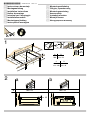
Preparation of assembly kitchen units,
figures 1/2/3/4
Built-in kitchen units: Minimum temperature resistance of
90°C.
Gap: Remove any shavings after performing cutting work.
Cut surfaces: Seal with heat resistant material.
Note: If the width of the gap for the built-in unit is 780 mm, use
the accessories supplied with the appliance.
Assembly over drawer, figure 2a
Metal objects stored inside the drawer could become very hot
due to the air recirculating from the hob ventilation system. If
this occurs, an intermediate support is recommended.
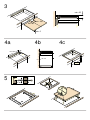
Intermediate support: A wooden panel can be used (figure 3) or
you may order a suitable accessory from our Technical
Assistance Service. The reference code for this accessory
is 680502.
Worktop: Must have a minimum thickness of 20 mm.
The distance between the top of the working surface and the top
of the drawer must be 65 mm.
Assembly over oven, figure 2b
Hob: must have a minimum thickness of 30 mm.
Note: If the distance between the hob and oven must be
increased, refer to the installation instructions for the oven.
Ventilation: The distance between the oven and the hob must be
at least 5 mm.
Installation above the dishwasher
An intermediate accessory must be installed. The accessory
may be ordered from our Technical Assistance Service. The
reference code for this accessory is 680502.
Worktop: Must have a minimum thickness of 20 mm and
maximum thickness of 40 mm.
The space between the top of the working surface and the top
of the dishwasher must be:
■ 60 mm if installed over a compact dishwasher.
■ 65 mm if installed over a full-size dishwasher.
Ventilation, figure 4
Ventilating the hob requires:
■ An opening on the upper part of the kitchen unit's rear wall
(figure 4a).
■ A separation between the rear part of the kitchen unit and
kitchen wall (figure 4b).
■ If the interior width of the kitchen unit is less than 750 mm, a
cut must be made in the side walls (figure 4c).
Installing the appliance, figures 5/6
Note: Wear protective gloves to fit the hob. The non-visible
surfaces may have sharp edges.
1. Installation of fastening guides, (figure 5):
– use the lower threaded holes on tiled worktops.
– For stone worktops, glue the guides (use thermosetting
adhesive tape suitable for joining metal and stone).
2. Connect the appliance to the mains and check that it works
correctly.
– See the rating plate for the voltage.
– Only connect the appliance in accordance with the
connection diagram (Fig. 6).
1. Brown
2. Black
3. Blue
4. Grey
5. Green-yellow
Note: Depending on the type of connection, the arrangement of
the clamps supplied by the factory may need to be changed.
Uninstalling the appliance
Disconnect the appliance from the mains.
Push the hob upwards from below to remove it.
Caution!
Damage to the appliance! Do not try to remove the appliance by
prying it out from above.
fr
Þ
Notice de montage
Remarques importantes
Sécurité : la sécurité pendant l'utilisation n'est garantie que si
l'installation a été effectuée de manière correcte du point de vue
technique et conformément à ces instructions de montage.
L'installateur sera responsable de tout dommage provoqué par
un montage incorrect.
Connexion électrique : ne peut être effectuée que par un
spécialiste autorisé. Il devra suivre les dispositions du
fournisseur d'électricité dans la zone.
Type de branchement : l'appareil fait partie de la classe de
protection I et ne peut être utilisé qu'avec une prise possédant
un conducteur de prise de terre.
Le fabricant se dégage de toute responsabilité quant au
fonctionnement inapproprié et aux possibles dommages
provoqués par des installations électriques non appropriées.
Installation : l'appareil doit être connecté à une installation fixe
et des moyens de déconnexion doivent être prévus sur
l'installation fixe, conformément aux réglementations de
l'installation.
Montage encastré sous le plan de travail : les plaques à
induction ne peuvent être installées que sur tiroir, des fours
avec ventilation forcée de la même marque ou des lave-
vaisselle de la même marque. Sous la plaque de cuisson, il
n'est pas possible d'installer des frigos, des fours sans
ventilation ou des lave-linge.
Câble d'alimentation : ne pas coincer le câble d'alimentation,
ne pas le faire passer sur des arêtes vives. S'il y a un four déjà
monté en dessous, faire passer le câble par les coins arrière du
four jusqu'au boîtier de connexion. Il doit être placé de façon à
ne toucher aucune partie chaude de la plaque de cuisson ou du
four.
Plan de travail : plat, horizontal, stable. Respectez les
instructions du fabricant du plan de travail.
Garantie : une mauvaise installation, un mauvais branchement
ou un montage inadapté peuvent conduire à la perte de validité
de la garantie du produit.
Remarque : Toute manipulation à l'intérieur de l'appareil, y
compris le remplacement du câble d'alimentation, devra être
effectuée par du personnel technique du service d'assistance
technique ayant reçu une formation spécifique.
Préparation des meubles de montage,
schémas 1, 2, 3 et 4
Meubles encastrés : capables de résister à une température
d'au moins 90 °C.
Creux d'encastrement : retirer les copeaux dus à la découpe.
Surfaces de découpe : sceller à l'aide d'un matériau résistant à
la chaleur.
Remarque : Si la largeur du creux d'encastrement est de
780 mm, utiliser les accessoires fournis avec l'appareil.
Montage sur tiroir, schéma 2a
Les objets métalliques qui se trouvent dans le tiroir pourraient
atteindre des températures élevées en raison de la recirculation
de l'air provenant de la ventilation de la plaque, c'est pourquoi il
est recommandé d'utiliser un support intermédiaire.
Support intermédiaire :il est possible d'utiliser un panneau en
bois (schéma 3) ou d'acheter un accessoire approprié auprès
de notre service d'assistance technique. Le code de référence
de cet accessoire est le 680502.
Plan de travail : son épaisseur minimum doit être de 20 mm.
La distance entre la partie supérieure du plan de travail et la
partie supérieure du tiroir doit être de 65 mm.
Montage sur four, schéma 2b
Plan de travail : son épaisseur minimum doit être de 30 mm.
Remarque : Veuillez consulter la notice de montage du four si la
distance entre la table de cuisson et le four doit être agrandie.
Ventilation : La distance entre le four et la table de cuisson doit
être d'au moins 5 mm.
Page is loading ...
Page is loading ...
Page is loading ...
Page is loading ...
Page is loading ...
Page is loading ...
Page is loading ...
Page is loading ...
Page is loading ...
-
 1
1
-
 2
2
-
 3
3
-
 4
4
-
 5
5
-
 6
6
-
 7
7
-
 8
8
-
 9
9
-
 10
10
-
 11
11
-
 12
12
-
 13
13
-
 14
14


Siemens EH875SB31E/01 User manual
- Category
- AV equipment stands
- Type
- User manual
- This manual is also suitable for
Ask a question and I''ll find the answer in the document
Finding information in a document is now easier with AI
in other languages
- italiano: Siemens EH875SB31E/01 Manuale utente
- français: Siemens EH875SB31E/01 Manuel utilisateur
- español: Siemens EH875SB31E/01 Manual de usuario
- Deutsch: Siemens EH875SB31E/01 Benutzerhandbuch
- русский: Siemens EH875SB31E/01 Руководство пользователя
- Nederlands: Siemens EH875SB31E/01 Handleiding
- português: Siemens EH875SB31E/01 Manual do usuário
- dansk: Siemens EH875SB31E/01 Brugermanual
- polski: Siemens EH875SB31E/01 Instrukcja obsługi
- Türkçe: Siemens EH875SB31E/01 Kullanım kılavuzu
- svenska: Siemens EH875SB31E/01 Användarmanual
- suomi: Siemens EH875SB31E/01 Ohjekirja
Related papers
-
Blaupunkt EH651BN17E Owner's manual
-
Bosch EH601MB11 User manual
-
Siemens EH475MG11E/21 User manual
-
Bosch PIV645F17E/01 User manual
-
Bosch HE13055/04 User manual
-
Siemens HB86K575/01 User manual
-
Bosch HBD421I10A(00) User manual
-
-
Bosch PID975N24E/21 User manual
-
Bosch HBA21B351Y/45 User manual
Other documents
-
Gaggenau CX 480 110 Installation Instructions Manual
-
Bosch PIP851F17E/01 Installation guide
-
Bosch HBN311E2/01 Installation guide
-
Vivanco WTS 1 Operating instructions
-
-
Vivanco WTS 3 Operating instructions
-
-
-
-