Jacobsen AR 250 Turbo Safety And Operation Manual
- Category
- Lawnmowers
- Type
- Safety And Operation Manual

Safety and Operation Manual
Manuale di sicurezza e d’uso
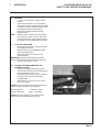
AVVISO: Questa macchina può causare gravi infortuni se
viene utilizzata in modo errato. Prima di accingersi ad
approntare, usare, mettere a punto o eseguire la
manutenzione di questa macchina, coloro che la utilizzano
ed i responsabili della manutenzione devono essere addestrati
all’impiego della macchina, devono essere informati dei pericoli,
e devono leggere l’intero manuale.
GB
English
RJ 100 122003
24491G-IT (rev.1)
AR 250 Turbo
Series: CE - Engine type: Kubota V1505-TBB-EC-1-S1
Product code: JHAF030
Serie: CE - Tipo di motore: Kubota V1505-TBB-EC-1-S1
Codice prodotto: JHAF030
WARNING: If incorrectly used this machine can cause severe
injury. Those who use and maintain this machine should be
trained in its proper use, warned of its dangers and should
read the entire manual before attempting to set up, operate,
adjust or service the machine.

© 2003, Ransomes Jacobsen Limited. All Rights Reserved
© 2003, Ransomes Jacobsen Limited. Tutti i diritti sono riservati

GB-1
JACOBSEN AR250 Series CE
SAFETY AND OPERATORS MANUAL
1 CONTENTS
2 INTRODUCTION
2.1 IMPORTANT .............................................................. 2
2.2 PRODUCT IDENTIFICATION ....................................... 2
2.3 GUIDELINES FOR THE DISPOSAL OF SCRAP
PRODUCTS ...............................................................2
2.3.1 DURING SERVICE LIFE ..............................................2
2.3.2 END OF SERVICE LIFE ............................................... 2
3 SAFETY INSTRUCTIONS
3.1 OPERATING INSTRUCTIONS .....................................4
3.2 SAFETY SIGNS ..........................................................4
3.3 STARTING THE ENGINE ............................................. 4
3.4 DRIVING THE MACHINE ............................................ 4
3.5 TRANSPORTING ........................................................4
3.6 LEAVING THE DRIVING POSITION ............................5
3.7 SLOPES ..................................................................... 5
3.8 BLOCKED CUTTING CYLINDERS .............................. 5
3.9 ADJUSTMENTS, LUBRICATION AND
MAINTENANCE .........................................................5
4 SPECIFICATIONS
4.1 ENGINE SPECIFICATION ............................................ 7
4.2 MACHINE SPECIFICATION ........................................7
4.3 DIMENSIONS ............................................................. 7
4.4 VIBRATION LEVEL .................................................... 7
4.5 SLOPES ..................................................................... 7
4.6 CUTTING UNIT SPECIFICATION ................................ 8
4.7 RECOMMENDED LUBRICANTS ................................. 8
4.8 CUTTING PERFORMANCE (AREA) ............................ 8
4.9 CONFORMITY CERTIFICATES .................................. 9
5 DECALS
5.1 SAFETY DECALS ..................................................... 11
5.2 INSTRUCTION DECALS ............................................ 11
6 CONTROLS
6.1 STARTER KEY SWITCH ............................................ 12
6.2 THROTTLE CONTROL LEVER .................................. 12
6.3 STEERING WHEEL RAKE ADJUSTMENT .................. 12
6.4 TRACTION FOOT PEDAL ......................................... 12
6.5 NEUTRAL LATCH (B) ............................................... 12
6.6 SPEED LIMITER ....................................................... 13
6.7 PARK BRAKES .......................................................... 13
6.8 HYDRAULIC LIFT LEVER ......................................... 13
6.9 UNIT COUNTERBALANCE CONTROL ....................... 14
6.10 CUTTING UNIT SWITCHES ....................................... 14
6.11 UNIT TRANSPORT STOP ......................................... 15
6.12 INSTRUMENT PANEL ............................................... 15
6.13 HOURMETER ............................................................ 16
6.14 BONNET RELEASE KEY ............................................ 16
7 OPERATION
7.1 DAILY INSPECTION .................................................. 17
7.2 OPERATOR PRESENCE AND SAFETY INTERLOCK
SYSTEM ................................................................... 18
7.3 OPERATING PROCEDURE ......................................... 19
7.4 STARTING THE ENGINE ............................................ 20
7.5 DRIVING ................................................................... 20
7.6 MOWING .................................................................. 21
7.7 TO STOP THE ENGINE .............................................. 21
7.8 PUSHING THE MACHINE WITH THE ENGINE
STOPPED ................................................................. 21
8 ADJUSTMENTS
8.1 HEIGHT OF CUT ....................................................... 22
8.2 GENERAL INSTRUCTIONS FOR GRAMMER SEATS . 23
8.3 SEAT (Grammer GS85/90)...................................... 25
8.4 AIR SUSPENSION SEAT (Grammer MSG75 -521) .. 26
8.4.1 WEIGHT ADJUSTMENT ............................................ 26
8.4.2 FORE/AFT ADJUSTMENT ......................................... 26
8.4.4 SEAT HEATER ........................................................... 27
8.4.5 LUMBAR SUPPORT ................................................. 27
8.4.3 BACKREST EXTENSION ........................................... 27
8.4.6 ARMRESTS .............................................................. 28
8.4.7 ARMREST ADJUSTMENT ........................................ 28
8.4.8 BACKREST ADJUSTMENT .......................................28
8.4.9 MAINTENANCE ........................................................ 29
9 MAINTENANCE
9.1 LUBRICATION AND MAINTENANCE CHART ............ 30
9.2 DAILY CHECKS (Every 8 working hours) ............. 32
10 GUARANTEE / SALES & SERVICE ............................ 33
CONTENTS PAGE CONTENTS PAGE

GB-2
JACOBSEN AR250 Series CE
SAFETY AND OPERATORS MANUAL
2 INTRODUCTION
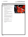
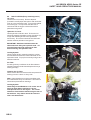
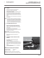
2.2 PRODUCT IDENTIFICATION
A Machine Name
B Serial Number
C Year of Manufacture
D Machine Weight
E Engine Power
A
B
C
DE
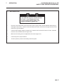
2.1 IMPORTANT
IMPORTANT: This is a precision machine and the service obtained from it depends on the way it is
operated and maintained.
This SAFETY AND OPERATORS MANUAL should be regarded as part of the machine. Suppliers of both
new and second-hand machines are advised to retain documentary evidence that this manual was provided
with the machine.
This machine is designed solely for use in customary grass cutting operations. Use in any other way is
considered as contrary to the intended use. Compliance with and strict adherence to the conditions of
operation, service and repair as specified by the manufacturer, also constitute essential elements of the
intended use.
Before attempting to operate this machine, ALL operators MUST read through this manual and make
themselves thoroughly conversant with Safety Instructions, controls, lubrication and maintenance.
Accident prevention regulations, all other generally recognized regulations on safety and occupational
medicine, and all road traffic regulations shall be observed at all times.
Any arbitrary modifications carried out on this machine may relieve the manufacturer of liability for any
resulting damage or injury.
It is important that during the life of the machine wearing and replaceable parts are disposed of in an
environmentally responsible way using the resources available in the country where it is used. There are
guidelines in this manual for the eventual decommissioning of the mower once it has no further use.

GB-3
JACOBSEN AR250 Series CE
SAFETY AND OPERATORS MANUAL
2 INTRODUCTION
2.3 GUIDELINES FOR THE DISPOSAL
OF SCRAP PRODUCTS
2.3.1 DURING SERVICE LIFE
Used oil, oil filters and engine coolant are
hazardous materials and should be handled in a safe
and environmentally responsible way.
In the event of a fluid leak, contain the spill to
prevent it entering the ground or drainage system.
Local legislation will dictate how such spills are to
treated.
Following the maintenance procedures laid out in
this manual will ensure that the impact the machine
has on the local environment is controlled.
When it has been identified that a turf care product
has no further functional value and requires disposal,
the following actions should be taken.
2.3.2 END OF SERVICE LIFE
These guidelines should be used in conjunction with
applicable Health, Safety and Environmental
legislation and use of approved local facilities for
waste disposal and recycling.
• Position the machine in a suitable location
for any necessary lifting equipment to be
used.
• Use appropriate tools and Personal
Protective Equipment (PPE) and take
guidance from the technical manuals
applicable to the machine.
• Remove and store appropriately:
1. Batteries
2. Fuel residue
3. Engine coolant
4. Oils
• Disassemble the structure of the machine
referring to the technical manuals where
appropriate. Special attention should be
made for dealing with ‘stored energy’ within
pressurised elements of the machine or
tensioned springs.
• Any items that still have a useful service
life as second hand components or can be
re-serviced should be separated and
returned to the relevant centre.
• Other worn out items should be separated
into material groups for recycling and
disposal consistent with available facilities.
More common separation types are as
follows:
• Steel
• Non ferrous metals
• Aluminium
• Brass
• Copper
• Plastics
• Identifiable
• Recyclable
• Non recyclable
• Not identified
• Rubber
• Electrical & Electronic Components
• Items that cannot be separated
economically into different material groups
should be added to the ‘General waste’
area.
• Do not incinerate waste.
Finally update machinery records to indicate that the
machine has been taken out of service and
scrapped. Provide this serial number to Jacobsen
Warranty department to close off relevant records.

GB-4
JACOBSEN AR250 Series CE
SAFETY AND OPERATORS MANUAL
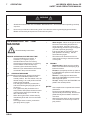
3 SAFETY INSTRUCTIONS
This safety symbol indicates important safety
messages in this manual. When you see this
symbol, be alert to the possibility of injury, carefully
read the message that follows, and inform other
operators.
3.1 OPERATING INSTRUCTIONS
• Ensure that the instructions in this book
are read and fully understood.
• No person should be allowed to operate
this machine unless they are fully
acquainted with all the controls and the
safety procedures.
• Never allow children or people unfamiliar
with these instructions to use this
machine. Local regulations may restrict
the age of the operator.
3.2 SAFETY SIGNS
• It is essential all safety labels are kept
legible, if they are missing or illegible they
must be replaced. If any part of the
machine is replaced and it originally
carried a safety label, a new label must be
affixed to the replacement part. New
safety labels are obtainable from
Ransomes dealers.
3.3 STARTING THE ENGINE
• Before starting the engine check that the
brakes are applied, drives are in neutral,
guards are in position and intact, and
bystanders are clear of the machine.
• Do not run the engine in a building without
adequate ventilation.
3.4 DRIVING THE MACHINE
• Before moving the machine, check to
ensure that all parts are in good working
order, paying particular attention to
brakes, tyres, steering and the security of
cutting blades.
• Replace faulty silencers, mow only in
daylight or good artificial light
• Always observe the Highway Code both on
and off the roads. Keep alert and aware at
all times. Watch out for traffic when
crossing or near roadways.
• Stop the blades rotating before crossing
surfaces other than grass.
• Remember that some people are deaf or
blind and that children and animals can
be unpredictable.
• Keep travelling speeds low enough for an
emergency stop to be effective and safe
at all times, in any conditions.
• Remove or avoid obstructions in the area
to be cut, thus reducing the possibility of
injury to yourself and/or bystanders.
• When reversing, take special care to
ensure that the area behind is clear of
obstructions and/or bystanders. DO
NOT carry passengers.
• Keep in mind that the operator or user is
responsible for accidents or hazards
occurring to other people or their
property.
• When the machine is to be parked,
stored or left unattended, lower the
cutting means unless the transport locks
are being used.
• While mowing, always wear substantial
footwear and long trousers. Do not
operate the equipment when barefoot or
wearing open sandals.
• Check the grass catcher frequently for
wear or deterioration. After striking a
foreign object. Inspect. the lawnmower
for damage and make repairs before
restarting and operating the equipment.
• If the machine starts to vibrate
abnormally, check immediately.
3.5 TRANSPORTING
• Ensure that the cutting units are
securely fastened in the transport
position. Do not transport with cutting
mechanism rotating.
• Drive the machine with due consideration
of road and surface conditions, inclines
and local undulations.
• Sudden decelerating or braking can
cause the rear wheels to lift.
• Remember that the stability of the rear of
the machine is reduced as the fuel is
used.

GB-5
JACOBSEN AR250 Series CE
SAFETY AND OPERATORS MANUAL
3 SAFETY INSTRUCTIONS
3.6 LEAVING THE DRIVING POSITION
• Park the machine on level ground.
• Before leaving the driving position, stop the
engine and make sure all moving parts are
stationary. Apply brakes and disengage all
drives. Remove the starter key.
3.7 SLOPES
TAKE EXTRA CARE WHEN WORKING ON
SLOPES
• Local undulations and sinkage will change
the general slope. Avoid ground conditions
which can cause the machine to slide.
• Keep machine speeds low on slopes and
during tight turns.
• Sudden decelerating or braking can cause
the rear wheels to lift. Remember there is
no such thing as a “safe” slope.
• Travel on grass slopes requires particular
care.
DO NOT USE ON SLOPES GREATER THAN 15°
IMPORTANT: When working on any slope set the
weight transfer, if fitted to its maximum (+) setting.
3.8 BLOCKED CUTTING CYLINDERS
• Stop the engine and make sure all moving
parts are stationary.
• Apply brakes and disengage all drives.
• Release blockages with care. Keep all parts
of the body away from the cutting edge.
Beware of energy in the drive which can
cause rotation when the blockage is released.
• Keep other people away from the cutting units
as rotation of one cylinder can cause the
others to rotate.
3.9 ADJUSTMENTS, LUBRICATION AND
MAINTENANCE
• Stop the engine and make sure all moving
parts are stationary.
• Apply brakes and disengage all drives.
• Read all the appropriate servicing instructions.
• Use only the replacement parts supplied by
the original manufacturer.
• When adjusting the cutting cylinders take
care not to get hands and feet trapped when
rotating cylinders.
• Make sure that other people are not touching
any cutting units, as rotation of one cylinder
can cause the others to rotate.
• To reduce the fire hazard, keep the engine,
silencer and battery compartments free of
grass, leaves or excessive grease.
• Replace worn or damaged parts for safety.
• When working underneath lifted parts or
machines, make sure adequate support Is
provided.
• Do not dismantle the machine without
releasing or restraining forces which can
cause parts to move suddenly.
• Do not alter engine speed above maximum
quoted in Engine Specification. Do not
change the engine governor settings or
overspeed the engine. Operating the engine
at excessive speed may increase the hazard
of personal injury.
• When refuelling, STOP THE ENGINE, DO
NOT SMOKE. Add fuel before starting the
engine, never add fuel while the engine is
running.
• Use a funnel when pouring fuel from a can into
the tank.
• Do not fill the fuel tank beyond the bottom of
the filler neck.
• Replace all fuel tank and container caps
securely.
• Store fuel in containers specifically designed
for this purpose.
• Refuel outdoors only and do not smoke while
refuelling.
• If fuel is spilled, do not attempt to start the
engine but move the machine away from the
area of spillage and avoid creating any source
of ignition until fuel vapours have dissipated.
• Allow the engine to cool before storing in any
enclosure.
• Never store the equipment with fuel in the
tank inside a building where fumes may reach
an open flame or spark.
• If the fuel tank has to be drained, this should
be done outdoors.
• Do not spill fuel onto hot components.
• When servicing batteries, DO NOT SMOKE,
and keep naked lights away.
• Do not place any metal objects across the
terminals.
• When Pressure Washing the Mower. Turn
the engine off and remove the starter key.
If the engine has been running, it should be
allowed to cool sufficiently to prevent damage
to the block and exhaust manifold. Never
force water into any electrical components,
the air cleaner or exhaust muffler as water
could enter the engine cylinder and cause
damage.

GB-6
JACOBSEN AR250 Series CE
SAFETY AND OPERATORS MANUAL
Hydraulic Fluid escaping under pressure
can penetrate skin and do serious
damage. Immediate medical assistance
must be sought.
WARNING
Batteries produce explosive gases and
contain corrosive acid and supply levels
of electrical current high enough to cause
burns.
WARNING
DO NOT USE ON SLOPES GREATER THAN 15°
WARNING
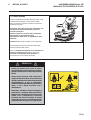
3 SAFETY INSTRUCTIONS
DANGER - Indicates an imminently hazardous
situation which, if not avoided, WILL result in death
or serious injury.
WARNING - Indicates a potentially hazardous
situation which, if not avoided, COULD result in
death or serious injury.
CAUTION - Indicates a potentially hazardous
situation which, if not avoided, MAY result in minor
or moderate injury and property damage. It may
also be used to alert against unsafe practices.
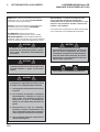
IMPORTANT: Transport speed is for highway
use only. Never select transport speed on grass
areas or uneven or unsurfaced roads or tracks.
The operating Instructions for the Cutting Units are
contained in a separate Publication .
California Proposition 65
Engine Exhaust, some of its constituents,
and certain vehicle components contain
or emit chemicals known to the state of
California to cause cancer and birth
defects or other reproductive harm.
WARNING
Before releasing transport latches it is
important that all cutting units are fully
raised.
1. Park the machine on level ground.
2. With the engine running at operating
speed raise the cutting units to their
maximum position by operating lift
levers whilst seated in the driving
position.
3. Disengage drives, stop the engine and
make sure all moving parts are
stationary. Apply brakes and remove
the starter key.
4. transport latches can now be released.
WARNING

GB-7
JACOBSEN AR250 Series CE
SAFETY AND OPERATORS MANUAL
4 SPECIFICATIONS
4.1 ENGINE SPECIFICATION
TYPE: Kubota 31.3KW (42HP) @ 3000
RPM, 4 cylinder (in line) Turbo
charged Diesel engine, 4 stroke,
water cooled, 1498cc (91.44
cu.in) with 12V electric start.
Model: V1505-T-E2B-RANUK-3
Maximum Speed: 3000 ± 50 RPM (No load)
Idle Speed: 1500 RPM
Oil Sump Capacity:6.4 litres (11.26 Imp.pints)
Fuel: No. 2-D Diesel fuel (ASTM D975)
4.2 MACHINE SPECIFICATION
Frame construction:Heavy duty formed steel chassis
with box section frame rails.
Cutting unit drive: Fixed displacement hydraulic
motors directly coupled to
cutting unit.
Transmission: Full time 4-wheel drive. Direct
coupled variable displacement
pump to direct coupled 29 cu in
front, 21 cu in rear wheel motors.
Speeds:
Cutting: 0 - 12km/h (0 - 7.5 mph)
FORWARD
Transport: 0 - 14km/h (0 - 8.5mph)
FORWARD
Reverse: 0 - 6.4km/h (0 -4 mph)
Steering: Hydrostatic power steering, with
adjustable tilt steering wheel.
Ground pressure: 14p.s.i. (1 kg/cm
2
)
Brakes: Hydrostatic braking with
mechanical type band parking
brakes, 260mm x 45mm
(10.25in x 1.75in) on front
wheels.
Fuel Tank
Capacity: 45.4 litres (10 Imp. galls) 12 US
galls
Hydraulic Tank
Capacity: 37.8 litres (8.3 Imp. galls) 10 US
galls
Battery: Exide 093 (SAE 500)
4.3 DIMENSIONS
Width of cut: 2.5 metres (98in)
Overall width: 2.6 metres(104in)
Overall width: 2.13 metres (84in)
(transport)
Overall height: 1.6 metres (63in)
Overall length: 3.1 metres (122in)
Overall weight of
machine: 1560kg (3432lb)
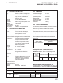
4.4 VIBRATION LEVEL
The machine was tested for whole body and hand/
arm vibration levels. The operator was seated in the
normal operating postion with both hands on the
steering mechanism. The engine was running and
the cutting device was rotating with the machine
stationary.
Standard ISO 5349: 1986 Mechanical vibration.
Guidelines for the measurement and the
assessment of human exposure to hand-
transmitted vibration.
Standard ISO 2631-1: 1985 Evaluation of human
exposure to whole body vibration -- Part 1: General
requirements.
OBRUT052RA
ECseireS
noitareleccAmrA/dnaH
level
HRroHLxaM
s/msnoitareleccA
2
qeAXqeAYqeAZ
998.0635.0645.0
eulaVtnanimoD998.0
4.5 SLOPES
DO NOT USE ON SLOPES GREATER THAN 15°
The slope 15° was calculated using static stability
measurements according to the requirements of
EN 836.
OBRUT052RA
ECseireS
ydoBelohW
noitareleccA
level
noitacoLroolF
s/msnoitareleccA
2
noitacoLtaeS
s/msnoitareleccA
2
xyzxyz
naeM7810.08120.04520.0120.03030.0520.0
SERUSSERPERYT
tcudorP
leehWtnorF leehWraeR
eziSeryTepyTeryTerusserPeryTeziSeryTepyTeryTerusserPeryT
052RA21-00.41x5.62
rp4carT
artlUnatiTisp02-41rab73.1-00.1
8-00.01x02
rp4carTartlUnatiTisp02-41rab73.1-00.1

GB-8
JACOBSEN AR250 Series CE
SAFETY AND OPERATORS MANUAL
4.6 CUTTING UNIT SPECIFICATION
General: Five 559mm (22in) rotary mulching/side
discharge decks supported by equal ratio
lift arms.
Drive: Fixed displacement hydraulic motors
directly coupled to cutting unit.
Control: Cutting unit lift lever with automatic shutoff
and safety interlock restart.
Construction:
Heavy duty, welded pressed steel.
Suspension:
Steerable floating head.
Cutting Blades:
Envirodeck
Patent pending twin blades. Lower blade
559mm (22in), upper blade 546mm
(21.5in)
Side Discharge
Low Lift Blade
Height of cut:
Adjustable in 6mm (0.25in) increments
19mm(0.75in) to 133mm(5.25in) no tool
required.
Rear roller:
102mm (4in) diameter smooth roller.
4.7 RECOMMENDED LUBRICANTS
Engine oil: Should be to MIL-L-2104C or to
A.P.I. Classification SE/SF/SG
grades. [10W-30]
Hydraulic Oil: To A.P.I. Classification CE/SF
grades
SAE 10W-30
Grease: Shell Darina R2, or equivilant.
4.8 CUTTING PERFORMANCE (AREA)
2.7 hectares/hr. at 12 km/hr. ( 6.67acres/hr at 7.5
mph)
10% allowance is included for normal overlaps and
turning at the end of each cut.

GB-9
JACOBSEN AR250 Series CE
SAFETY AND OPERATORS MANUAL
4 SPECIFICATIONS
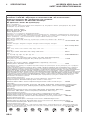
4.9 CONFORMITY CERTIFICATES
EC Declaration of Conformity • Déclaration de Conformité CE •
EG Conformiteits-Declaratie • EG-Konformitatsbescheinigung •
Certificato di Conformità CE • EF Konformitetserklæring •
EU Uppfyllandecertifikat • Ilmoitus yhdenmukaisuudesta ey:n sääntöjen kanss • Declaración de
Conformidad de la CE • Declaração de Conformidade da CE
We the undersigned • Nous, soussignés • Wij, ondergetekenden • Wir, die Unterzeichnenden • Noi sottoscritti Undertegnede •
Undertecknarna • Me allekirjoittaneet • Los abajo firmantes • Nós, abaixo assinados
Ransomes Jacobsen Limited
West Road, Ransomes Europark,
Ipswich, England, IP3 9TT
Declare that the machine Described Below • Certifions que la machine suivante • verklaren dat onderstaand beschreven machine •
erklären, dass die nachfolgend beschriebene Maschine • Dichiariamo che la macchina descritta di seguito • Erklærer, at følgende maskine •
Deklarerar att den maskin som beskrivs nedan • vahvistamme, että alla kuvattu kone • Certificamos que la máquina descrita abajo •
declaramos que a máquina a seguir descrita
Make & Type • Nom & Type • Merk & Type • Marke und Typ • Marca e tipo •
Fabrikat og type • Fabrikat & typ • Malli ja tyyppi • Marca y Tipo • Marca & Tipo.................................................... Jacobsen AR250 Turbo
Category • Modèle • Categorie • Kategorie • Categoria • Kategori • Luokka •
Categoría • Categoria ............................................................................................................................................... Ride on Rotary Mower
Series • Série • Serie • Sarja .................................................................................................................................... CE
Engine • Motor • Moteur • Motore • Moottori ............................................................................................................. Kubota
Type • Typ • Tipo • Tyyppi ........................................................................................................................................ V1505-T-E2B-RAN.UK-1
Net Installed Power • Puissance nette • Netto geïnstalleerd vermogen •
installierte Antriebsleistung • Potenza installata netta • Nettoeffekt installere •
Installerad nettoeffekt • Asennettu nettoteho • Potencia instalada neta •
Potência real instalada ............................................................................................................................................. 31.3 KW
Cutting Width • Largeur de coupe • Maaibreedte • Schnittbreite •
Larghezza di taglio • Klippebredde • Klippbredd • Leikkuuleveys •
Anchura de corte • Largura do corte ...................................................................................................................... 250cm
Complies with the provisions of the following European directives and amendments and the regulations transposing it into national law •
Est conforme aux prescriptions des normes, modifications et règles européennes suivantes • voldoet aan de bepalingen van de volgende
Europese Richtlijnen en Amendementen, alsmede aan de verordeningen die deze omzetten in nationale wetgeving • den Bestimmungen der
folgenden Europa-Richtlinien einschließlich aller Änderungen und Ergänzungen sowie den Vorschriften, die diese in das nationale Recht
umsetzen, entspricht • soddisfa quanto previsto dalle seguenti direttive ed emendamenti europei e dalle normative che li riportano in legge
nazionale • Overholder bestemmelserne i følgende EF-direktiver med ændringer og i de forordninger, hvorved de omsættes til national lov •
Uppfyller kraven i följande europeiska direktiv med tillägg och regler transponerade till nationell lagstiftning • täyttää seuraavana mainittujen
Euroopan direktiivien ja muutosten ja säännösten asettamat edellyt• Cumple las las siguientes regulaciones europeas siguientes
Machinery Safety Directive • Directive de sécurité des machines •
Richtlijn Machineveiligheid • Richtlinie zur Maschinensicherheit •
Direttiva sulla sicurezza del macchinario • Maskinsikkerhedsdirektivet •
Maskinsäkerhetsdirektiv • Koneen turvallisuutta koskeva direktiivi •
Directiva de seguridad de maquinaria • Directiva de segurança de máquinas ...................................................... 98/37/EC
EMC Directive • Directive de compatibilité électromagnétique • EMC Richtlijn •
EMK-Richtlinie • Direttiva EMC • EMC-direktivet • Elektromagnetiskt kompatibilitetsdirektiv •
EMC-direktiivi • Directiva EMC ................................................................................................................................... 89/336/EC
ROPS Directive • Directive de ROPS • ROPS Richtlijn • ROPS-Richtlinie •
Direttiva ROPS • ROPS-direktivet • ROPS direktiv • ROPS-direktiivi • Directiva ROPS ............................................ 86/298/EC
Noise in the Environment Directive • Directiv • Richtlijn Milieulawaa •
Richtlinie zum Umgebungslärm • Direttiva sulla rumorosità nell’ambiente •
Støjemissionsdirektivet • Bullerdirektiv • Melu ympäristöä koskevassa direktiivissä •
Directiva sobre ruido en el ambiente • Directiva Ruído no Ambiente ...................................................................... 2000/14/EC
Measured Sound Power Level • Niveau de puissance sonore assuré •
Gegarandeerd geluidsvermogenniveau • Garantierter Schallleistungspege •
Livello di potenza del suono misurato • Målt lydeffektniveau • Uppmätt ljudfraftsnivå •
Mitattu åånitehon taso • Nivel de Potencia Sonora • Nívelde intensidade de som medido ..................................... 104 dB(A) LWA
Guaranteed Sound Power Level • Niveau de puissance sonore assuré •
Gegarandeerd geluidsvermogenniveau • Garantierter Schallleistungspege •
Livello di potenza del suono misurato • Garanteret lydeffektniveau •
Garanterad ljudtrycksnivå • Taattu äänitehon taso • Nivel Garantizado de Potencia Sonora •
Nível garantido de intensidade sonora .................................................................................................................... 105 dB(A) LWA
Page is loading ...

GB-11
JACOBSEN AR250 Series CE
SAFETY AND OPERATORS MANUAL
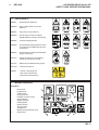
5 DECALS
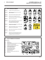
5.1 SAFETY DECALS
A903491 Read Operator's Manual.
A903489 Keep a Safe Distance from the
Machine.
A903492 Stay Clear of Hot Surfaces.
A903488 Do Not Open or Remove Safety
Shields While the Engine is Running.
A903496 Caution Rotating Blades.
A903493 Avoid Fluid Escaping Under Pressure.
Consult Technical Manual for Service
Procedures.
A903490 Do Not Remove Safety Shields While
Engine is Running.
A911410 Danger of Explosion if the Battery
Terminals are Short Circuited.
A911416 Maximum permitable working slope.
A911434 Caution Diesel Fuel
4153197 Caution, Stop Engine &
Remove the Starter Key
Before Pressure Washing
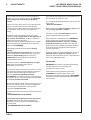
5.2 INSTRUCTION DECALS
Description
A. Diesel Fuel
B. Hydraulic Oil
C. Jacking Point
D. Cutting Unit Lift
E. Fwd/Rev Traction Pedal
F. Cutter Engage
G. Weight Transfer
H. Parking Brake
I. Ignition Switch
J. Tyre Pressure
K. CE Approval
L. Maximum Sound Power Level
M. Engine Rev's
4153197
4153197

GB-12
JACOBSEN AR250 Series CE
SAFETY AND OPERATORS MANUAL
6 CONTROLS
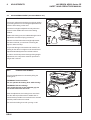
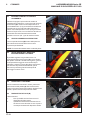
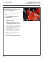
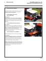
6.1 STARTER KEY SWITCH
The starter key (A) should be turned clockwise to
the 'pre-heat' (No. 2) position to heat the glowplugs
when the green warning lamp goes out, on warning
lamp disply module, turn the starter key clockwise
to the 'start' (No. 3) position to start the engine. After
starting, the key should be released and allowed to
return automatically to the 'on' (No. 1) position for
normal running.
6.2 THROTTLE CONTROL LEVER
The lever (B) should be moved away from the
operator to increase the engine speed and towards
the operator to decrease the engine speed.
NOTE: Engine should be used at full speed.
6.3 STEERING WHEEL RAKE ADJUSTMENT
The steering wheel is adjustable for rake. The
clamping release knob (A) is situated on the side of
the control console on the left hand side. To adjust
turn the clamping knob anticlockwise to release and
pivot the steering wheel backwards and forwards to
obtain desired setting then lock in position by
turning clamping knob clockwise.
6.4 TRACTION FOOT PEDAL
To move the machine forward press the front of the
foot pedal (A). To reverse depress the rear of the foot
pedal. When the pedal is released it will return to its
neutral position.
6.5 NEUTRAL LATCH (B)
Has two functions:
1. The engine cannot be started when the
Neutral Latch is depressed.
2. The FWD/REV pedal will not work as
described if the Neutral Latch is not
simultaneously depressed.

GB-13
JACOBSEN AR250 Series CE
SAFETY AND OPERATORS MANUAL
6 CONTROLS
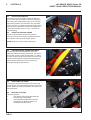
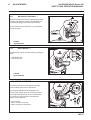
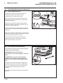
6.6 SPEED LIMITER
The speed limiter (A) is operated by pivoting the
lever under the footpedal. When positioned under
the footpedal the machine is limited to cutting
speed, when not under the footpedal transport speed
is availabe.
6.7 PARK BRAKES
Push the pedal forward (A) until it locks to set
parking brake. Release parking brake by pushing the
brake pedal at the same time lever (B) is pulled up.
6.8 HYDRAULIC LIFT LEVER
The cutting units can be raised and lowered by
control lever (A) situated on the right hand side of
the operators seat and can be operated as follows:
To lift: Move the lever backwards and hold in position
until the units are at the required height.
To lower: Move the lever forwards and hold in this
position, the units will lower to ground level. The
lever automatically returns to a neutral position when
released.
NOTE: If any unit is raised out of work then lowered
into work again the blades will not rotate until the
mow foot switch is depressed.
NOTE: The units will only lift and lower when the
engine is running.

GB-14
JACOBSEN AR250 Series CE
SAFETY AND OPERATORS MANUAL
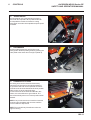
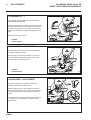
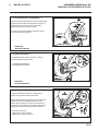
6.9 UNIT COUNTERBALANCE CONTROL
Cutting unit ground pressure can be varied within
preset limits and is controlled by the handwheel (A)
on the right hand side of the operator's seat located
next to the lift/lower lever. The handwheel is turned
clockwise to reduce the groundweight of the cutting
unit, improving slope climbing ability.
The handwheel is turned anti clockwise to increase
the ground weight of the unit. Increased down
pressure will reduce the likelyhood of cutting unit
bounce when cutting undulating ground. When
cutting level ground the normal setting is midway
way between the maximum and minimum positions.
6.10 CUTTING UNIT SWITCHES
To commence cutting ensure speed limiter is in
mow position and the units have been lowered.
Push bottom of the rocker switch (G) and depress
foot switch (A) Push top of rocker switch to stop
cutter unit rotation. (Cutting units stop rotating
automatically when raised.)
6 CONTROLS

GB-15
JACOBSEN AR250 Series CE
SAFETY AND OPERATORS MANUAL
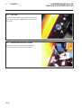
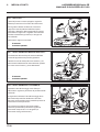
6.11 UNIT TRANSPORT STOP
Depressing the pedal (A) while lifting the cutting
units allows the cutting units to be raised for ma-
chine transport.
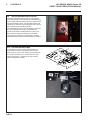
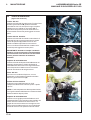
6.12 INSTRUMENT PANEL
A. ENGINE PREHEAT INDICATOR LAMP
Colour green, on when the ignition switch is turned
clockwise to the pre-heat position. Once the lamp
goes out the engine can be started.
B. ENGINE TEMPARATURE GUAGE
Indicates current temparature of engine, whilst
running.
C. HYDRAULIC OIL WARNING LAMP
Colour red, on when the hydraulic oil temperature
reaches a preset level. If the lamp comes on bring the
machine to a stop, disengage the cutting units, apply
the parking brake and stop the engine.
D. CHARGING WARNING LAMP
Colour red, on when ignition is switched on and will go out
when the engine is started. If the light comes on while
the engine is running, the fan belt may be slipping or
broken or a fault in the electrical system is indicated and
should be investigated. STOP IMMEDIATELY.
E. ENGINE OIL PRESSURE WARNING LAMP
Colour red, on when the ignition is switched on, and will
go out once the engine has started. If the light comes on
while the engine is running - STOP IMMEDIATELY as
this indicates that the engine oil pressure is too low.
Check the level of oil in the sump and top up as
necessary. Check the oil pressure sender switch.
Continued operation may cause extensive damage to the
engine.
F. FUEL GUAGE
Located to the left of the engine temparature guage.
Monitors fuel level.
6 CONTROLS

GB-16
JACOBSEN AR250 Series CE
SAFETY AND OPERATORS MANUAL
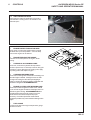
6.13 HOURMETER
Located on the lefthand side of the steering tower,
above the parking brake. (A) Records engine running
hours.
6 CONTROLS
6.14 BONNET RELEASE KEY
Release bonnet by inserting key (A) into base of
latch bracket.

GB-17
JACOBSEN AR250 Series CE
SAFETY AND OPERATORS MANUAL
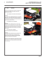
7.1 DAILY INSPECTION
1. Perform a visual inspection of the entire unit, look for signs of wear, loose hardware and missing or
damaged components. Check for fuel and oil leaks to ensure connections are tight and hoses and
tubes are in good condition.
2. Check the fuel supply, radiator coolant level, crankcase oil level and air cleaner is clean. All fluids
must be at the full mark with the engine cold.
3. Make sure all cutting units are adjusted to the same height of cut.
4. Check all tyres for proper inflation.
5. Test the operator presence and safety interlock system.
The daily inspection should be performed
only when the engine is off and all fluids
are cold. Lower implements to the
ground, engage parking brake, stop
engine and remove ignition key.
CAUTION
7 OPERATION

GB-18
JACOBSEN AR250 Series CE
SAFETY AND OPERATORS MANUAL
7 OPERATION
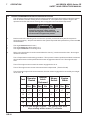
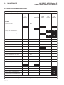
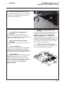
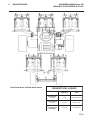
7.2 OPERATOR PRESENCE AND SAFETY INTERLOCK SYSTEM
1. The operator presence & safety interlock system prevents the engine from starting unless the neutral
latch is released, and the mowing device is switched off. The system also stops the engine if the
operator leaves the seat with the mowing device engaged or the neutral latch depressed.
2. Perform each of the following tests to ensure the operator presence & safety interlock system is
functioning properly. Stop the test and have the system inspected and repaired if any of the tests fail
as listed below:
• The engine does not start in test 1;
• The engine does start during tests 2 or 3.
• The engine continues to run during test 4.
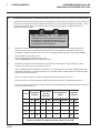
3. Refer to the chart below for each test and follow the check () marks across the chart. Shut engine
off betwen each test.
Test 1: Represents normal starting procedure. The operator is seated, pedal neutral latch is released,
the operators feet are off the pedals and the mower engagement device is off. The engine should
start.
Test 2: The engine must not start if the mower engage device is on.
Test 3: The engine must not start if the neutral latch is depressed. (Traction Pedal)
Test 4: Start the engine in the normal manner, then turn mower engage device on and lift your weight
off the seat.
Never operate the equipment with the
operator presence & safety interlock
system disengaged or malfunctioning. Do
not disconnect or bypass any switch.
WARNING
tseT
rotarepO
detaeS
lartueN
hctaL
desaeleR
rewoM
hctiwS
enignE
stratS
seYoNseYoNnOffOseYoN
1
2
3
4
tsumstinugnittuceh
T.taesffothgiewruoytfiL
sdnoces)7(nevesnihtiwgnitatorpots

GB-19
JACOBSEN AR250 Series CE
SAFETY AND OPERATORS MANUAL
7 OPERATION
7.3 OPERATING PROCEDURE
1. Under no circumstances should the engine be started without the operator seated on the tractor.
2. Do not operate tractor or attachments with loose, damaged or missing components. Whenever
possible mow when grass is dry
3. First mow in a test area to become thoroughly familiar with the operation of the tractor and control
levers.
4. Study the area to determine the best and safest operating procedure. Consider the height of the
grass, type of terrain, and condition of the surface. Each condition will require certain adjustments
or precautions.
5. Never direct discharge of material toward bystanders, nor allow anyone near the machine while in
operation. The owner/operator is responsible for injuries inflicted to bystanders and/or damage to their
property.
6. Use discretion when mowing near gravel areas (roadway, parking areas, cart paths, etc.). Stones
discharged from the implement may cause serious injuries to bystanders and/or damage the
equipment.
7. Disengage the drive motors and raise the implements when crossing paths or roads. Look out for
traffic.
8. Stop and inspect the equipment for damage immediately after striking an obstruction or if the
machine begins to vibrate abnormally. Have the equipment repaired before resuming operation.
To help prevent injury, always wear safety
glasses, leather work shoes or boots, a
hard hat and ear protection.
CAUTION
Pick up all debris you can find before
mowing. Enter a new area cautiously
Always operate at speeds that allow you to
have complete control of the tractor
CAUTION
Before you clean, adjust, or repair this
equipment, always disengage all drives,
lower implements to the ground, engage
parking brake, stop engine and remove
key from ignition switch to prevent injuries.
WARNING
Page is loading ...
Page is loading ...
Page is loading ...
Page is loading ...
Page is loading ...
Page is loading ...
Page is loading ...
Page is loading ...
Page is loading ...
Page is loading ...
Page is loading ...
Page is loading ...
Page is loading ...
Page is loading ...
Page is loading ...
Page is loading ...
Page is loading ...
Page is loading ...
Page is loading ...
Page is loading ...
Page is loading ...
Page is loading ...
Page is loading ...
Page is loading ...
Page is loading ...
Page is loading ...
Page is loading ...
Page is loading ...
Page is loading ...
Page is loading ...
Page is loading ...
Page is loading ...
Page is loading ...
Page is loading ...
Page is loading ...
Page is loading ...
Page is loading ...
Page is loading ...
Page is loading ...
Page is loading ...
Page is loading ...
Page is loading ...
Page is loading ...
Page is loading ...
Page is loading ...
Page is loading ...
Page is loading ...
Page is loading ...
Page is loading ...
Page is loading ...
Page is loading ...
-
 1
1
-
 2
2
-
 3
3
-
 4
4
-
 5
5
-
 6
6
-
 7
7
-
 8
8
-
 9
9
-
 10
10
-
 11
11
-
 12
12
-
 13
13
-
 14
14
-
 15
15
-
 16
16
-
 17
17
-
 18
18
-
 19
19
-
 20
20
-
 21
21
-
 22
22
-
 23
23
-
 24
24
-
 25
25
-
 26
26
-
 27
27
-
 28
28
-
 29
29
-
 30
30
-
 31
31
-
 32
32
-
 33
33
-
 34
34
-
 35
35
-
 36
36
-
 37
37
-
 38
38
-
 39
39
-
 40
40
-
 41
41
-
 42
42
-
 43
43
-
 44
44
-
 45
45
-
 46
46
-
 47
47
-
 48
48
-
 49
49
-
 50
50
-
 51
51
-
 52
52
-
 53
53
-
 54
54
-
 55
55
-
 56
56
-
 57
57
-
 58
58
-
 59
59
-
 60
60
-
 61
61
-
 62
62
-
 63
63
-
 64
64
-
 65
65
-
 66
66
-
 67
67
-
 68
68
-
 69
69
-
 70
70
-
 71
71
-
 72
72


Jacobsen AR 250 Turbo Safety And Operation Manual
- Category
- Lawnmowers
- Type
- Safety And Operation Manual
Ask a question and I''ll find the answer in the document
Finding information in a document is now easier with AI
in other languages
- italiano: Jacobsen AR 250 Turbo
Related papers
-
Ransomes TR30001, TR30002 Owner's manual
-
-
-
-
Ransomes 67924 Owner's manual
-
-
Jacobsen USAD004 Maintenance Manual
-
Textron USAD004 Owner's manual
-
-
Other documents
-
Bertolini NTR 340 Owner's manual
-
-
Bertolini BTR 550 Owner's manual
-
Oleo-Mac IP 1150 S Owner's manual
-
Atco GT36H Operating instructions
-
Comet Patriot User manual
-
-
Oleo-Mac PW 136 C Owner's manual
-
-