
J-A2608
Drill Press
SKÖTSELINSTRUKTIONER OCH RESERVDELSLISTA
INSTRUCTIONS AND SPARE PARTS LIST
BEDIENUNGSANLEITUNG UND ERSATZTEILLISTE
WALTER MEIER (Manufacturing) Inc.
427 New Sanford Rd.
LaVergne, Tennesseee 37086

2
Warranty and Service
Walter Meier (Manufacturing) Inc., warrants every product it sells. If one of our tools needs service or repair, one of our
Authorized Service Centers located throughout the United States can give you quick service. In most cases, any of
these Walter Meier Authorized Service Centers can authorize warranty repair, assist you in obtaining parts, or perform
routine maintenance and major repair on your JET® tools. For the name of an Authorized Service Center in your area
call 1-800-274-6848.
MORE INFORMATION
Walter Meier is consistently adding new products to the line. For complete, up-to-date product information, check with
your local Walter Meier distributor, or visit waltermeier.com.
WARRANTY
JET products carry a limited warranty which varies in duration based upon the product (MW = Metalworking, WW =
Woodworking).
WHAT IS COVERED?
This warranty covers any defects in workmanship or materials subject to the exceptions stated below. Cutting tools,
abrasives and other consumables are excluded from warranty coverage.
WHO IS COVERED?
This warranty covers only the initial purchaser of the product.
WHAT IS THE PERIOD OF COVERAGE?
The general JET warranty lasts for the time period specified in the product literature of each product.
WHAT IS NOT COVERED?
Five Year Warranties do not cover woodworking (WW) products used for commercial, industrial or educational
purposes. Woodworking products with Five Year Warranties that are used for commercial, industrial or education
purposes revert to a One Year Warranty. This warranty does not cover defects due directly or indirectly to misuse,
abuse, negligence or accidents, normal wear-and-tear, improper repair or alterations, or lack of maintenance.
HOW TO GET SERVICE
The product or part must be returned for examination, postage prepaid, to a location designated by us. For the name of
the location nearest you, please call 1-800-274-6848.
You must provide proof of initial purchase date and an explanation of the complaint must accompany the merchandise.
If our inspection discloses a defect, we will repair or replace the product, or refund the purchase price, at our option.
We will return the repaired product or replacement at our expense unless it is determined by us that there is no defect,
or that the defect resulted from causes not within the scope of our warranty in which case we will, at your direction,
dispose of or return the product. In the event you choose to have the product returned, you will be responsible for the
shipping and handling costs of the return.
HOW STATE LAW APPLIES
This warranty gives you specific legal rights; you may also have other rights which vary from state to state.
LIMITATIONS ON THIS WARRANTY
WALTER MEIER (MANUFACTURING) INC., LIMITS ALL IMPLIED WARRANTIES TO THE PERIOD OF THE LIMITED
WARRANTY FOR EACH PRODUCT. EXCEPT AS STATED HEREIN, ANY IMPLIED WARRANTIES OR
MERCHANTABILITY AND FITNESS ARE EXCLUDED. SOME STATES DO NOT ALLOW LIMITATIONS ON HOW
LONG THE IMPLIED WARRANTY LASTS, SO THE ABOVE LIMITATION MAY NOT APPLY TO YOU.
WALTER MEIER SHALL IN NO EVENT BE LIABLE FOR DEATH, INJURIES TO PERSONS OR PROPERTY, OR
FOR INCIDENTAL, CONTINGENT, SPECIAL, OR CONSEQUENTIAL DAMAGES ARISING FROM THE USE OF OUR
PRODUCTS. SOME STATES DO NOT ALLOW THE EXCLUSION OR LIMITATION OF INCIDENTAL OR
CONSEQUENTIAL DAMAGES, SO THE ABOVE LIMITATION OR EXCLUSION MAY NOT APPLY TO YOU.
Walter Meier sells through distributors only. The specifications in Walter Meier catalogs are given as general
information and are not binding. Members of Walter Meier reserve the right to effect at any time, without prior notice,
those alterations to parts, fittings, and accessory equipment which they may deem necessary for any reason
whatsoever. JET® branded products are not sold in Canada by Walter Meier.

3
A
Skötselinstruktioner – Manual – Bedienungsanleitung
Denna skötselinstruktion och reservdels-
lista är utarbetad för Er som använder,
ansvarar eller ger service för denna ma-
skin. Därför bör den som närmast ansva-
rar för om/eller använder maskinen ha
bekväm tillgång till den instruktion och
reservdelslista
Läs instruktionen innan Ni installerar och
startar maskinen. Maskinen är enkelt och
robust byggd, men vi kan ej garantera
dess perfekta funktion om den behandlas
felaktigt. Gör er därför väl förtrogen med
maskinen och prova de olika detaljerna i
manöversystem och inställningar. Be-
härskar Ni maskinen kan Ni också utnytt-
ja dess egenskaper fullt ut och få maxi-
mal livslängd på alla ingående kompo-
nenter.
Varje maskins noggrannhet och kapacitet
provas vid fabriken. Erfaren personal
kontrollerar både mekaniska och elekt-
riska funktioner enligt ett standardiserat
program. Vi kan därför garantera att
utförandet ligger på en hög och jämn
nivå.
Följer Ni våra anvisningar och Ert goda
omdöme är vi övertygade om att Ni blir
belåtna med Er nya maskin. Skulle trots
allt problem uppstå, kontakta vår återför-
säljare eller oss direkt.
These care instructions and the spare
parts lists are prepared for those persons
who use, are responsible for, or serve
this machine. Therefore, the person who
most closely uses or is responsible for
the machine should have easy access to
these care instructions and spare parts
list.
Please read the instructions, before you
install and start the machine. The ma-
chine has a simple and robust design,
but we cannot guarantee that it will func-
tion perfectly if it is handled improperly.
Therefore, be sure to make yourself
familiar with the machine and examine
the various details of the control system
and settings. If you can master the ma-
chine, you can also take full advantage of
its features and get maximum life out of
all the associated components.
The accuracy and capacity of each ma-
chine is tested at the factory. Experi-
enced personnell checks both the me-
chanical and electrical functions accord-
ing to a standardized program. We can
therefore guarantee a high level of per-
formance.
If you follow our instructions and use
your best judgement, we are certain that
you will be happy with your new machi-
ne. Nevertheless, if problems do occur,
please contact us directly or contact our
retailer.
Diese Bedienungsanleitung und Ersatz-
teilliste richtet sich an Maschinenbenut-
zer, Maschinenverantwortliche und Ser-
vicepersonal. Maschinenverantwortliche
oder Maschinenbenutzer sollten jederzeit
auf diese Dokumentation zugreifen kön-
nen.
Lesen Sie diese Anleitung, bevor Sie die
Maschine installieren und in Betrieb
nehmen. Die Maschine ist einfach und
robust konstruiert. Bei unsachgemäßer
Behandlung können wir eine einwandfre-
ie Funktionsweise jedoch nicht garantie-
ren. Machen Sie sich daher mit der Ma-
schine vertraut und testen Sie die einzel-
nen Bedienelemente und Einstellungs-
möglichkeiten. Durch eine umfassende
Beherrschung der Maschine können Sie
deren Leistungsvermögen voll ausschöp-
fen und die maximale Lebensdauer aller
enthaltenen Bauteile gewährleisten.
Genauigkeit und Leistung aller Maschi-
nen werden im Herstellungswerk getes-
tet. Anhand eines standardisierten Ab-
laufs kontrolliert erfahrenes Personal die
mechanischen und elektrischen Funktio-
nen. Auf diese Weise können wir höch-
ste Qualität garantieren.
Wenn Sie unsere Anweisungen befolgen
und Ihre Erfahrungen nutzen, werden Sie
beim Umgang mit dieser Maschine mehr
als zufrieden sein. Sollten trotzdem Pro-
bleme auftreten, wenden Sie sich an
unseren Händler oder direkt an uns.
Säkerhetsföreskrifter – Safety Instructions – Sicherheitshinweise
Rätt använd är denna maskin en av de
bästa med avseende på design och
säkerhet. Varje maskin som används
felaktigt kan emellertid alltid utgöra en
olycksrisk. Det är absolut nödvändigt att
de som använder maskinen har lärt sig
hur man använder den korrekt. De skall
läsa och förstå denna manual såväl som
alla skyltar som finns på maskinen. Un-
derlåtenhet att följa säkerhetsföreskrifter
kan orsaka olyckstillbud.
When used correctly, this is one of the
best machines in terms of design and
safety. However, any machine that is
used improperly can always pose a safe-
ty risk. It is absolutely necessary that
those persons using the machine have
learned how to use it correctly. They
should read and understand this material
as well all the signs on the machine.
Neglecting to follow the safety instruc-
tions can cause the risk of an accident.
Bei korrekter Anwendung ist diese Ma-
schine ein Spitzengerät in puncto Design
und Sicherheit. Unsachgemäß ange-
wandte Maschinen stellen ein hohes
Risiko dar. Es ist unbedingt notwendig,
daß das Bedienungs- und Wartungsper-
sonal über die korrekte Funktionsweise
der Machine informiert ist. Jeder Anwen-
der muss vor dem Arbeiten mit der Ma-
schine diese Anleitung sowie alle Ma-
schinenschilder lesen. Eine Nichtbeach-
tung der Sicherheitshinweise stellt eine
potenzielle Gefahrensituation dar.
Varning!
• Felanvändning av denna maskin kan
orsaka allvarliga olyckor.
• Maskinen måste installeras, använ-
das och underhållas korrekt.
Warning!
• Improper use of this machine can
cause serious personal injury.
• The machine must be installed and
maintained correctly.
Warnung!
• Der unsachgemäße Umgang mit
dieser Maschine kann schwere Per-
sonenschäden verursachen.
• Die Maschine muss korrekt instal-
liert und gewartet werden.

4
Generella säkerhetsföreskrifter – General Safety Regulations – Allgemeine Sicherheits-
vorschriften
Alla maskiner med roterande verktyg kan
orsaka olyckor. Det är därför viktigt att
Du som operatör är medveten om olycks-
risken och följer följande föreskrifter.
• Använd kläder och personlig
skyddsutrustning som gör att Du
inte kan fastna i det roterande verk-
tyget.
• Använd skyddsglasögon om risk för
spån- eller kylvätskestänk föreligger
eller om lokala regler finns om det-
ta.
• Håll rent runt maskinen så att du
inte snubblar och faller mot roteran-
de verktyg.
• Se till att arbetsstycket är ordentligt
låst i bordet. Använd aldrig handen
för att hålla arbetsstycket.
• Se alltid till att maskinens strömbry-
tare står i läge 0 när du skall byta
verktyg eller rengöra maskinen.
Borsta aldrig bort spån under tiden
maskinen arbetar.
• Använd korrekta verktyg. Se till att
rätt varvtal och rätt matning är in-
ställd för verktyget. Försäkra Dig
om att verktyget är avsett för arbe-
tet.
• Se till att huvud och bord är ordent-
ligt fastlåsta före start.
All machines with rotating parts can cau-
se accidents. Therefore, it is important
that as an operator you are aware of the
risk of an accident and follow the guideli-
nes below:
• Wear clothing and personal safety
equipment that cannot get caught in
the rotating drilling and tapping
tools.
• Use eye protection if there is a risk
of shavings or coolant splattering, or
if there are local regulations in this
regard.
• Keep the area around the machine
clean so that you do not trip and fall
against the rotating tool.
• Make sure that the work piece is
properly clamped to the table. Never
use your hands to hold the work
piece.
• Always make sure that the machi-
ne's electric switch is in the 0 posi-
tion when changing the drilling and
tapping tools or cleaning the machi-
ne. Never brush shavings away whi-
le the machine is working.
• Use proper drilling and tapping
tools. Make sure that the proper
speed and the proper feed rate is
set for the drilling and tapping tools.
Be sure that the drilling and tapping
tools is intended for the work you
are doing.
• Make sure that heads and tables are
properly locked in place before star-
ting.
Alle Maschinen mit rotierenden Werkze-
ugen können Unfälle verursachen. Sämt-
liche Anwender müssen sich dieser Un-
fallgefahr bewusst sein und die folgen-
den Hinweise beachten:
• Tragen Sie nur Arbeitskleidung und
persönliche Schutzausrüstung, mit
der Sie nicht am rotierenden Werk-
zeug hängenbleiben können.
• Tragen Sie eine Schutzbrille, wenn
Späne oder Kühlflüssigkeit herumfli-
egen oder austreten können bzw.
wenn dies durch lokale Sicherheits-
bestimmungen vorgeschrieben ist.
• Halten Sie den Bereich um die Ma-
schine sauber. Andernfalls besteht
Stolpergefahr mit anschließender
Berührung rotierender Werkzeuge.
• Das Werkstück muss fest auf dem
Bohrtisch befestigt sein. Halten Sie
Werkstücke niemals mit der Hand
fest.
• Der Maschinenschalter muss sich in
der Stellung "0" befinden, wenn Sie
Werkzeuge wechseln oder die Ma-
schine reinigen. Bürsten Sie niemals
Späne ab, während die Maschine in
Betrieb ist.
• Setzen Sie die korrekten Werkzeuge
ein. Achten Sie darauf, daß für das
Werkzeug die richtige Drehzahl und
der richtige Vorschub eingestellt
sind. Vergewissern Sie sich, daß das
Werkzeug für die jeweilige Verwen-
dung vorgesehen ist.
• Achten Sie darauf, daß Bohrkopf und
Bohrtisch vor Arbeitsbeginn fest ver-
riegelt sind.
Vid installation – Installation – Installationsvorschriften
• Undvik att installera maskinen i
fuktig, smutsig eller dåligt belyst mil-
jö.
• Försäkra Er om att maskinen har
alla nödvändiga skydd.
• Elektriska installationer skall utföras
av behörig elektriker.
• Försäkra Er om att maskinen är
stadigt uppställd eller förankrad.
• Avoid installing the machine in a
humid, dirty or badly illuminated en-
vironment.
• Be sure that the machine possesses
all necessary protections.
• Electric installations have to be exe-
cuted by a qualified electrician.
• Be sure that the machine is steadly
put up and positioned.
• Die Maschine sollte nicht in feuchten,
schmutzigen und/oder schlecht be-
leuchteten Räumen aufgestellt wer-
den.
• Die Schutzvorschriften müssen
absolut beachtet werden.
• Der elektrische Anschluss muss von
einem Fachmann durchgeführt wer-
den.
• Die Maschine muss mit einer Ma-
schinen-Wasserwaage ordentlich
ausgerichtet sein.
Vid användande – During Use – Verwendung
• Använd aldrig maskinen om den
saknar nödvändiga skydd.
• Följ gängse regler för maskinan-
vändning avseende personlig
skyddsutrustning.
• Undvik om möjligt att använda ar-
betshandskar.
• Arbeta inte i maskinen med löst
sittande klädsel eller smycken. An-
vänd hårnät om nödvändigt.
• Sträck Dig aldrig över maskinen när
den är igång.
• Lämna aldrig maskinen påslagen.
• Stoppa alltid maskinen när den inte
• Never use the machine if it is mis-
sing the necessary protection.
• Follow the current regulations for
using the machine in terms of per-
sonal safety equipment.
• As far as possible, avoid using wor-
king gloves.
• Do not work with the machine with
loose clothing or jewelry. Use a hair
net if necessary.
• Never stretch over the machine
when it is running.
• Never leave the machine turned on.
• Always stop the machine when not
•
Verwenden Sie die Maschine nur,
wenn alle erforderlichen Schutzvor-
richtungen vorhanden sind.
• Befolgen Sie beim Umgang mit der
Maschine die allgemeingültigen Re-
geln zur persönlichen Schutzausrüs-
tung.
• Soweit möglich, keine Arbeitshand-
schuhe verwenden.
• Arbeiten Sie nicht an der Maschine
mit loser Bekleidung oder Schmuck.
Falls erforderlich, tragen Sie ein
Haarnetz.
• Beugen Sie sich nie über eine im

5
används.
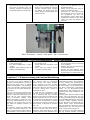
• Använd borrskydd. Borrskydd leve-
reras bara till maskiner med CE-
märkning. Vid byte av verktyg trycks
borrskyddet uppåt och viks åt sidan.
being used.
• Use drilling protection. Drilling pro-
tection is only supplied for machines
with the CE-label. When changing
the drilling and tapping tools, the
drilling shield is pushed upward and
bent to the side.
Betrieb befindliche Maschine
• Lassen Sie die Maschine nie un-
beaufsichtigt laufen.
• Halten Sie die Maschine stets an,
wenn Sie nicht benutzt wird.
• Verwenden Sie einen Bohrschutz.
Ein Bohrschutz wird nur mit Maschi-
nen ausgeliefert, die eine CE-
Kennzeichnung tragen. Beim Werk-
zeugwechsel drücken Sie den Bohr-
schutz nach oben und klappen ihn
zur Seite.
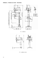
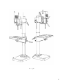
Bild 1. Borrskydd – Picture 1. Drill guard – Abb. 1. Bohrschutz
Vid service och underhåll – Service and Maintenance – Service und Wartung
• Se alltid till att spänningen till ma-
skinen är frånslagen.
• Följ alltid instruktionerna i denna
manual.
• Modifiera aldrig maskinen utan att
rådfråga vår återförsäljare.
• Always make sure that the power to
the machine is off.
• Always follow the instructions in this
manual.
• Never alter the machine without
consulting our retail dealer.
• Trennen Sie die Maschine stets von
der Stromquelle, bevor Sie Arbeiten
an ihr ausführen.
• Befolgen Sie stets die Anweisungen
in diesem Dokument.
• Nehmen Sie ohne vorherige Rück-
sprache mit unserem Händler keiner-
lei Änderungen an der Maschine vor.
CE-märkning och försäkran om överenskommelse – CE-labelling and Declaration of
Compliance – CE-Kennzeichnung und Konformitätserklärung
Om denna maskin är CE-märkt betyder
det att den vid leverans uppfyller de
tillämpliga ”Väsentliga Hälso- och Säker-
hetskrav” som anges i EU:s så kallade
Maskinsäkerhetsdirektiv. Om förändring-
ar görs som påverkar maskinens säker-
het ansvarar den som utför förändringar-
na för dessa.
Som bevis på att kraven uppfylles med-
levereras en EU-försäkring om överens-
kommelse, utfärdad av Machinery Scan-
dinavia AB för varje enskild maskin.
Denna EU-försäkran omfattar också
tillbehör tillverkade av Machinery Scan-
dinavia AB. Dokumentationen är en vär-
dehandling som skall bevaras väl och
som alltid ska medfölja maskinen vid
försäljning.
Om maskinen används för andra ända-
mål eller med andra tillbehör än som
anges i denna instruktion måste säkerhe-
ten säkerställas i varje enskilt fall. Ansva-
If this machine has a CE-label, then it
upon delivery fulfils the appropriate
"Critical Health and Safety Require-
ments" specified in the EU's so-called
Machine Safety Directive. If changes are
made which affect the machine's safety,
the person making these changes is
responsible for them.
As proof that the requirements have
been met, an EU Declaration of Compli-
ance is delivered with each machine,
prepared by Machinery Scandinavia AB.
This EU declaration also covers accesso-
ries manufactured by Machinery Scandi-
navia AB. The documentation is valuable
and should be properly preserved and
should always accompany the machine
when sold.
If the machine is used for other purposes
or with accessories other than what is
specified in these instructions, its safety
must be ensured in each individual case.
Wenn diese Maschine eine CE-
Kennzeichnung besitzt, dann erfüllt Sie
bei ihrer Lieferung die ”grundlegenden
Gesundheits- und Sicherheitsvorgaben”
der EU-Richtlinie zur Maschinensicher-
heit. Wenn Änderungen vorgenommen
werden, die die Maschinensicherheit
beeinträchtigen, trägt derjenige die Ver-
antwortung, der diese Änderungen aus-
geführt hat.
Als Beleg dafür, daß alle Vorgaben erfüllt
wurden, liegt jeder Maschine eine von
Machinery Scandinavia AB ausgefertigte
EU-Konformitätserklärung bei. Diese EU-
Erklärung umfasst ebenfalls Zubehör,
das von Machinery Scandinavia AB her-
gestellt wurde. Diese Dokumentation
stellt eine wichtige Urkunde dar, die gut
aufzubewahren und der Maschine bei
einem Verkauf stets beizulegen ist.
Wenn die Maschine zu anderen Zwecken
oder mit anderem Zubehör eingesetzt

6
rig är den som utför den och kan i vissa
fall kräva ny CE-märkning och utfärdan-
de av ny EU-försäkran om överenskom-
melse.
Responsibility lies with the person who
operates it, and in certain cases, a new
CE-label or new EU Declaration of Com-
pliance may be required.
wird als in dieser Anleitung angegeben,
ist die Sicherheit in jedem einzelnen Fall
zu gewährleisten. Verantwortlich dafür ist
die jeweils ausführende Person. In bes-
timmten Fällen kann eine neue CE-
Kennzeichnung und die Ausfertigung
einer neuen EU-Konformitätserklärung
erforderlich sein.
Installation – Installation – Installation
Uppsättning – Set-up – Aufstellung
• Kontrollera att maskinen inte har
skadats under transporten. Om så är
fallet kontakta omedelbart vår återför-
säljare.
• Placera maskinen på ett stabilt under-
lag. Ett mjukt mellanlägg av gummi
eller dylikt kan med fördel läggas mel-
lan maskinens fotplatta och underla-
get. Förankra maskinen med bultar
om så erfordras.
• Tvätta bort det rostskyddsmedel som
maskinen är behandlad med vid leve-
rans. Använd inte för mycket lös-
ningsmedel eftersom lösningsmedel
även löser infettning. Tvätta verktygs-
infästningen i borrspindeln speciellt
noga.
• Check that the machine has not
been damaged during transport. If
this is the case, contact our retail
dealer immediately.
• Place the machine on a steady foun-
dation. A soft rubber pad or similar
item can be placed between the
machine's foot plate and the founda-
tion. Anchor the machine with bolts
if required.
• Clean the machine from the rust-
protection the machine is treated
with during delivery. Do not use too
much solvent, since the solvent can
also remove the lubrication.
• Kontrollieren Sie die Maschine auf
eventuelle Transportschäden. Set-
zen Sie sich bei Beschädigungen
umgehend mit unserem Händler in
Verbindung.
• Stellen Sie die Maschine auf einer
stabilen Unterlage auf. Es empfiehlt
sich, zwischen Grundplatte und Un-
terlage eine weiche Zwischenlage
aus Gummi o.ä. zu platzieren. Falls
erforderlich, verankern Sie die Ma-
schine mit Bolzen.
• Waschen Sie das Rostschutzmittel
ab, mit dem die Maschine im Liefer-
zustand behandelt ist. Setzen Sie
dabei nicht zu viel Lösungsmittel ein,
da auf diese Weise die Schmierung
entfernt werden kann. Reinigen Sie
die Werkzeughalterung in der Bohrs-
pindel besonders gründlich.
Inkoppling – Electrical Connection – Anschluss
Inkopplingen skall alltid utföras av behö-
rig elektriker.
• Kontrollera att rätt spänning tillförs
maskinen.
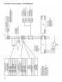
• Koppla enligt bifogat kopplingssche-
ma. Koppla in direkt på huvudmo-
torns motorskydd eller, när det gäller
flerspindliga maskiner, i en kopp-
lingsdosa.
• Kontrollera att borrspindeln har rätt
rotationsriktning.
Electrical installations should always be
performed by authorized electricians.
• Make sure that the correct voltage is
supplied to the machine.
• Set up the electrical connections
according to the attached circuitry
diagram. Connect the electricity di-
rectly on the main motor's automatic
circuit breaker.
• Make sure that the drilling spindle
has the correct rotation direction.
Der Anschluss ist stets von einem aus-
gebildeten Elektriker vorzunehmen.
• Kontrollieren Sie, ob die Maschine
mit der richtigen Spannung versorgt
wird.
• Nehmen Sie den Anschluss anhand
des beiliegenden Schaltplans vor.
Schließen Sie den Motorschutz des
Hauptmotors direkt oder bei mehr-
spindligen Maschinen an einer An-
schlussdose an.
• Überprüfen Sie, ob die Drehrichtung
der Bohrspindel korrekt ist.
Smörjning – Lubrication – Schmierung
Samtliga kullager och kugghjul är infetta-
de från fabrik.
• Kontrollera växellådans infettning
efter några års drift.
• Smörj matningsväxellådan (för ma-
skiner med sådan) och övriga rörli-
ga delar genom smörjkopparna.
• Matningsväxellådans snäckväxel
ligger i ett oljebad. Fyll på olja ge-
nom påfyllningshålet till mitten på
nivåglaset (ca 0,3 liter). Lämplig olja
bör en viskositet av 11 °E vid 50 °C.
Se oljerekommendation i bilagan.
OBS! Maskiner med automatisk matning
levereras utan olja i matningsväxellådan.
All ball bearings and gear wheels are
lubricated at the factory.
• Check the gear box's lubrication
after several years of use.
• Lubricate the feed gearbox (for ma-
chines equipped with one) and other
movable parts by using the lubrica-
ting cups.
• The feed gear box's worm gear sits
in an oil bath. Add oil via the filling
hole up to the middle of the level in-
dicator (approx. 0.3 liters). Proper oil
should have a viscosity of 11 °E at
50 °C. See oil recommendations in
the supplement.
NOTE! Machines with automatic feed are
not supplied with oil in the feed gearbox.
Alle Kugellager und Zahnräder sind ab
Werk geschmiert.
• Kontrollieren Sie die Schmierung des
Getriebes nach mehreren Betriebs-
jahren.
• Schmieren Sie das Vorschubgetriebe
(falls vorhanden) sowie alle anderen
beweglichen Teile über die Schmier-
buchsen.
• Das Schneckengetriebe des Vor-
schubgetriebes liegt in einem Ölbad.
Füllen Sie durch das Füllloch Öl bis
zur Mitte das Schauglases auf (ca.
0,3 l). Geeignetes Öl sollte eine Vis-
kosität von 11°E bei 50 °C aufweisen
(siehe Ölempfehlung in der Beilage).
HINWEIS! Maschinen mit automati-
schem Vorschub werden ohne Öl im
Vorschubgetriebe geliefert.

7
Manöverorgan – Operating Tools – Bedienelemente
Inställning av spindelvarvtal – Setting the Spindle Speed – Spindeldrehzahl einstellen
Varvtalen ställs in med de två växelhand-
tagen på spindelhusets vänstra sida.
Ställ in enligt skylten på framsidan. Ma-
skinen måste stå still när växling görs.
Skulle någon växel vara svår att få i läge,
rotera spindelnosen för hand.
The rotation speed is set using the two
gear levers on the left side of the spindle
case. Set them according to the sign on
the front side. The machine must be at a
stand still to make the switch.
If any of the gears are difficult to get into
position, rotate the spindle nose manual-
ly.
Be sure that the automatic circuit
breaker is off.
Die Drehzahl wird mittels der beiden
Griffe auf der linken Seite des Spindel-
gehäuses eingestellt. Richten Sie sich
dabei nach dem Schild auf der Vorder-
seite. Zum Wechseln der Drehzahl muss
die Maschine still stehen.
Wenn eine Einstellung nur schwer vor-
genommen werden kann, drehen Sie die
Spindelnase per Hand.
Handhavande – Handling – Bedienung
Val av hastighet – Choice of Speed – Wahl der Drehzahl
Maskinen är försedd med en 2-
hastighetsmotor.
• Ställ in önskat läge (1 eller 2) med
vredet
• Välj spindelhastighet med de två
växelhandtagen på maskinens
vänstra sida. Se skylten på maski-
nens framsida.
• Rotera spindelnosen för hand om
någon växel är svår att få i läge.
OBS! Maskinen får inte växlas under
gång.
The machine is equipped with a 2-speed
motor.
• Set the desired position (1 or 2) with
the dial
• Select the spindle speed, using the
two gear levers on the left side of
the machine. See the sign on the
front side of the machine.
• If any of the gears are difficult to get
into position, rotate the spindle nose
manually.
NOTE! The machine cannot be shifted
during operations.
Die Maschine ist mit einem Motor mit
zweifacher Drehzahlumschaltung aus-
gestattet.
• Stellen Sie per Schalter die ge-
wünschte Drehzahl ein (1 oder 2).
• Die Spindelgeschwindigkeit wird mit
Hilfe der beiden Griffe auf der linken
Maschinenseite eingestellt. Richten
Sie sich dabei nach dem Schild auf
der Vorderseite.
• Wenn eine Einstellung nur schwer
vorgenommen werden kann, drehen
Sie die Spindelnase per Hand.
HINWEIS! Die Drehzahl darf während
des Betriebs nicht gewechselt werden.
Automatisk reversering – Automatic Reversing – Automatische Umkehr
• Vrid strömbrytaren till läge gäng-
ning.
• Ställ in önskat gängdjup med borr-
djupsstoppet.
Vid inställt gängdjup ändrar spindeln
automatiskt rotationsriktning genom att
faserna till motorn ändras. Spindelvarvta-
let får inte överstiga 440 rpm. Max antal
reverseringar är 5 per minut. För att få
högre kvalitet på gängningen rekom-
menderar vi att flytande gängtapphållare
används.
OBS! Automatisk matning skall inte an-
vändas vid gängreversering.
• Turn the power switch to the threa-
ding position.
• Set the desired threading depth with
the drill depth stop.
If the thread depth is set, the spindle
automatically changes its direction of
rotation by changing the phases to the
motor. The speed of the spindle must not
exceed 440 rpm. The maximum number
of reversals is 5 per minute. In order to
get better quality threading, we recom-
mend using a floating tap wrench.
NOTE! Do not use automatic feeding
during reverse threading.
• Drehen Sie den Schalter in die Stel-
lung für das Gewindeschneiden.
• Stellen Sie mit dem Bohrtiefen-
anschlag die gewünschte Gewinde-
tiefe ein.
Bei der eingestellten Bohrtiefe ändert die
Spindel automatisch die Drehrichtung,
indem die Motorphasen gewechselt wer-
den. Die Spindeldrehzahl darf 440 U/min
nicht überschreiten. Es können maximal
5 Umkehrungen pro Minute stattfinden.
Um beim Gewindeschneiden eine höhere
Qualität zu erzielen, empfehlen wir den
Einsatz schwimmender Gewindebohrhal-
ter.
HINWEIS! Bei einer Umkehrung darf
kein automatischer Vorschub verwendet
werden.
Verktygsutdrivare – Drill Ejector – Werkzeugaustreiber
Maskinen är utrustad med automatisk
verktygsutdrivare. Mellan spindelhylsans
nos och spindelhuset finns en spärr som
gör att spindeln aldrig går upp i sitt övre
läge.
1. Se till att klokopplingen för manuell
matning är införd.
2. Vik ut spärren och för spindelhylsan
till sitt övre läge med nedmatnings-
handtaget. Därvid stöts verktyget ut.
3. Vik tillbaka spärren.
Verktyget kan ha fastnat hårt i spindeln t
The machine is equipped with an auto-
matic drill ejector. Between the nose of
the spindle sleeve and the spindle case,
there is a stopper that prevents the
spindle from ever reaching its upper
position.
1. Make sure that the claw coupling for
manual feed is inserted.
2. Bend out the stopper and bring the
spindle sleeve to its upper position
with the lower feed lever. The boring
tool should be pushed out.
3. Bend the stopper back.
Die Maschine ist mit einem automati-
schen Werkzeugaustreiber ausgestattet.
Zwischen der Nase der Spindelhülse und
dem Spindelgehäuse befindet sich eine
Sperre, die verhindert, daß sich die
Spindel über ihre obere Stellung hinaus-
bewegt.
1. Vergewissern Sie sich, daß die
Klauenkupplung für den manuellen
Vorschub hineingeschoben ist.
2. Klappen Sie die Sperre nach außen
und bewegen Sie die Spindelhülse
mit dem Vorschubhandgriff in ihre
obere Stellung. Dadurch wird das

8
ex genom hårt borrtryck och värmeför-
ändring i spindeln. I sådant läge rekom-
menderar vi att en utdrivningskil används
i stället för den automatiska verktygsut-
drivaren.
OBS! Se alltid till att verktygens tunga är
väl rengjord. Därmed undviks onödigt
slitage på borrspindeln infästning och att
verktyget fastnar i spindeln.
The boring tool may become stuck in the
spindle, e.g. via hard drilling pressure
and heat changes in the spindle. In this
case, we recommend using an expeller
wedge instead of the automatic drill ejec-
tor.
NOTE! Always be sure that the boring
tool's tongue is well-cleaned. This avoids
unnecessary wear and tear of the drilling
spindle and/or the boring tool getting
caught in the spindle.
Werkzeug herausgestoßen.
3. Klappen Sie die Sperre zurück.
Durch einen hohen Bohrdruck oder eine
Temperaturänderung in der Spindel kann
das Werkzeug in der Spindel festsitzen.
In diesem Fall empfehlen wir den Einsatz
eines Austreibkeils anstelle des automa-
tischen Werkzeugaustreibers.
HINWEIS! Achten Sie stets darauf, daß
das Werkzeug gründlich gereinigt ist.
Dadurch wird ein unnötiger Verschleiß an
der Bohrspindelhalterung oder ein Fest-
sitzen des Werkzeugs vermieden.
Växellåda – Drive Gear Box – Getriebe
Skall växellådan demonteras förfares
enligt följande:
De fyra skruvar, som förbinder växellå-
dan med spindelhuset, skruvas bort.
Fläktkåpa och fläkt borttages från under-
sidan av spindelhuset. Med lätta slag på
rotoraxeln lossas växellådan, som sedan
lyftes bort. Växellådshuset som är delat
vertikalt, sammanhålles av 4 st skruvar,
som borttages, varefter växellådan kan
delas. Axlarna kan då lyftas ur och bli
tillgängliga för vidare demontering.
Vid hopläggning av växellådan tillses att
växelföraren kommer i spåret på kopp-
lingen. Då växellådan sättes på spindel-
huset, kontrolleras att kilarna i spindeln
sitter på plats och att kilspåren i utgåen-
de axeln kommer mitt för kilarna.
When it is necessary to disassemble the
drive gear box:
Remove the four screws that connect the
drive gearbox to the quill housing. Then
take away the fan cover and the fan from
the quill housing. By knocking slightly on
the rotor shaft the drive gearbox can be
removed. The gear box casting, consis-
ting of two halves can be taken apart by
loosening the four screws. All shafts can
now be taken out for further disassemb-
ling.
When re-assembling the drive gearbox,
check that the shift pin fits properly into
the groove of the clutch. When re-placing
the drive gearbox on the quill housing, it
must be checked that the driving keys in
the spindle are in place and that they will
fit properly the corresponding key ways
on the gearbox output shaft.
Zur Demontage des Getriebes verfahre
man folgendermassen:
Die vier Schrauben, die das Getriebe mit
dem Spindelgehäuse verbinden, werden
entfernt. Ventilatordeckel und Ventilator
werden von der Unterseite des Spindel-
gehäuses abgenommen. Mit leichten
Schlägen auf die Motorwelle wird das
Getriebe gelöst und danach abgenom-
men. Das vertikal geteilte Getriebege-
häuse wird mit vier Schrauben zusam-
mengehalten. Werden diese entfernt,
kann das Getriebe geöffnet werden. Die
Wellen können dann herausgehoben
werden und sind zur weiteren Demonta-
ge zugänglich.
Beim Zusammenbau des Getriebes sollte
man darauf achten, daß die Schaltpins in
die Nuten der Kupplungen kommen.
Beim Aufsetzen des Getriebes auf das
Spindelgehäuse muss beachtet werden,
daß die Keilnuten in die herausragende
Welle mitten über die Keile greifen.
Spindeln – Spindle – Die Spindel
Spindeln är lagrad i spindelhylsan med
ett koniskt rullager nedtill och ett radial-
kullager upptill. För justering av lager-
glappet finns upptill på spindeln en mut-
ter. Den blir åtkomlig på följande sätt:
1. Montera av djupmåttstången från
spindeloket och mata ur spindeln.
2. Håll hela tiden i borrspindeln så att
den ej skadas.
3. Låt den nu uppspända returfjädern
återgå sakta till ospänt läge.
4. Justera glappet för spindellagringen,
var noga med att känna efter så att
det inte går tungt.
5. Montera i spindeln i huset igen ge-
nom att förspänna returfjädern med
nedmatningen ca: 2 varv på mat-
ningsaxeln och för upp spindeln.
6. Känn efter att båda kilarna styr in i
spindelförlängarens spår och att
kuggarna på mataraxeln griper in i
kuggstången på spindelhylsan.
7. Låt spindeln återgå och kontrollera
matningshandtagens läge, justeras
med omflyttning av läge vid upp-
släpp av spindel. Återmontera djup-
måttstången.
The spindle is journalled in the quill by a
taper roller bearing at the bottom and by
a radial ball bearing at the top. At the top
end of the spindle, there is a nut, with
which the play in the taper bearing can
be adjusted. This nut can be reached,
when the quill is removed from the ma-
chine as follows:
1. Remove the depth stop rod and feed
out the complete quill.
2. Hold the quill, so that it doesn’t fall out
and gets damaged.
3. Loosen the spring pressure by letting
the handle slowly return.
4. Adjust the play at the top end of the
quill. Make sure it doesn’t turn heavily.
5. Re-assemble the quill by turning one
of the handles in the feed shaft about
two turns for counter balancing the
quill, and put back the quill.
6. Make sure the keys on the spindle
coincide with the key ways in the
spindle shaft and that the teeth of the
feed shaft get the grip of the quill feed
rack.
7. Let the quill return to the top position,
check the position of the feed han-
dles, and adjust by the feed shaft
teeth grip another rack position. Re-
Die Spindel ist unten in einem Kegelrol-
lenlager und oben in einem Rollenlager
in der Pinole gelagert. Zur Einstellung
des Lagerspieles befindet sich oben an
der Spindel eine Mutter. Diese wird zu-
gänglich, nachdem die Pinole auf folgen-
de Weise aus dem Spindelgehäuse ge-
nommen wurde:
1. Die Tiefenmassstange entfernen und
die Pinole aus dem Bohrkopf austrei-
ben.
2. Eine Hand unter die Pinole halten,
damit die Pinole nicht herausfällt und
beschädigt wird,
3. Die Rückholfeder langsam wieder
zurückkehren lassen.
4. Das Spiel des Lagers am Ende der
Pinole justieren, so dass sie gut um-
läuft.
5. Die Pinole in das Gehäuse wie folgt
zurücksetzen: Die Vorschubwelle
zweimal drehen, um die Rückholfe-
der wieder aufzuspannen und dann
die Spindel zurücksetzen.
6. Die Keile der Spindel müssen wieder
gut in die Nuten der Spindelverlänge-
rung fassen, und die Zähne der Vor-
schubwelle gut in die Zahnstange der
Pinole eingreifen.

9
assemble the depth stop rod.
7. Die Pinole wieder zurückkehren las-
sen und die Position der Handgriffe in
einer anderen Position der Zahn-
stange justieren. Die Tiefenmass-
stange wieder zurück montieren.
Spindelns utbalansering – Counter Balancing the Spindle – Ausgleich der Spindel
Fjäderhuset för spindelns utbalansering
borttages på följande sätt.
Demontera elboxen från spindelhuset
och låt det hänga vid sidan om.
Lossa skruven, som låser fast fjäderhu-
set på undersidan av spindelhuset.
Låt fjäderhuset vrida sig, så att fjädern
kommer i viloläge. Huset med isittande
fjäder kan nu tas bort.
Vid montering tryckes fjäderhuset med
fjädern in på sin plats i slitsen på axeln.
Se till att fasen i slitsen går mot första
utgående böj på fjädern, vrid sedan
moturs till önskad utbalansering erhållits
på spindeln. Sedan låses huset fast med
skruven på spindelhusets undersida.
The spring housing for counter balancing
of the spindle is removed as follow:
Unmount the electric box from the spin-
dle house and put aside (you do not have
to disconnect the cables).
Undo the screw, which keeps the spring
housing to the spindle housing.
Let the spring housing turn to release the
pressure on the spring. The housing with
included spring can now be removed.
When assembling, press the spring
housing into the slot on the shaft.
Make sure that the slot goes against the
first bending on the spring. Turn in
counter-clockwise until desired counter
balancing is reached and then lock the
spindle housing with the screw.
Das Federgehäuse zum Ausgleich der
Spindel wird auf folgende Weise entfernt:
Lösen Sie den Elektrokasten vom Spin-
delgehäuse und lassen Sie den Kasten
an der Seite hängen (die Kabel brauchen
nicht gelöst werden).
Die Schraube lockern, die das Federge-
häuse am Spindelgehäuse festhält.
Das Federgehäuse sich drehen lassen,
bis die Feder entspannt.
Das Gehäuse mit darin liegender Feder
kann nun abgenommen werden.
Beim Zusammenbau das Federgehäuse
in den Schlitz der Welle drücken.
Die Abschrägung des Schlitzes gegen
den Uhrzeigersinn drehen, bis der ge-
wünschte Ausgleich der Spindel erreicht
ist und dann das Gehäuse mit der
Schraube an das Spindelgehäuse fest-
schrauben.
Motor – Motor – Motor
Om statorn i spindelhuset skall bytas på
grund av motorfel, tillgår detta på följan-
de sätt:
MASKINEN GÖRES STRÖMLÖS, och
växellåda, matningsaxel samt spindelhyl-
sa borttages enligt ovan. Linjekablar och
motorkablar lossas från polomkopplaren.
Säkra spindelhuset med lyft och lyftband.
Lossa skruv och lyft spindelhuset av
pelaren, därefter borttages spindelhusets
höj- och sänkanordning.
De två stoppskruvarna på spindelhusets
högra sida, som fixerar statorn borttages,
och statorns läge markeras i huset.
Genom att stöta spindelhusets undersida
mot ett lämpligt underlag bringar man
sedan statorn att nedåt glida ur huset.
Den nya statorn pressas sedan från
husets undersida in i samma läge som
den tidigare hade.
If it is necessary to remove the stator,
proceed as follow:
DISCONNECT THE MACHINE FROM
THE MAINS.
Remove the drive gear box, the quill and
the feed drive shaft as indicated above.
The motor and the line cables are remo-
ved from the pole-change switch. Secure
the quill housing with a lifting band. Loo-
sen the screw and lift off the quill hou-
sing. Then remove the elevating mecha-
nism for the drill head.
The two stop screws on the left side of
the quill housing, which keep the stator in
its position, are removed and the position
of the stator is marked in the housing. By
knocking lightly on the underside of the
quill housing against a suitable surface,
the stator will slide downwards out of the
housing.
The new stator is then pressed into the
housing from below in the same position
as the previous one.
Muss wegen Motorschaden der Stator im
Spindelgehäuse ausgetauscht werden,
verfahre man folgendermaßen:
DIE MASCHINE WIRD STROMLOS
GEMACHT und Getriebe, Pinole sowie
Vorschubwelle entfernt. Anschluss- und
Motorkabel werden vom Polumschalter
gelöst. Das Spindelgehäuse mit Hebe-
band sichern. Die Schrauben lockern und
das Spindelgehäuse von der Säule ab-
nehmen. Dann die Höhenverstelleinrich-
tung des Spindelgehäuses wegnehmen.
Die zwei Klemmschrauben auf der linken
Seite des Spindelgehäuses, die den
Stator fixieren, werden gelöst und die
Lage des Stators am Gehäuse markiert.
Durch Aufstoßen der Unterseite des
Spindelgehäuses auf eine geeignete
Unterlage erreicht man, daß der Stator
nach unten aus dem Gehäuse gleitet.
Der neue Stator wird dann von der Un-
terseiten des Gehäuses in dieselbe Lage
gepresst, die der alte Stator vorher hatte.
Reparationer – Repairs – Reparaturen
Vid rätt handhavande, underhåll och
skötsel är inga reparationer förutom
eventuellt byte av fjäderhus nödvändiga.
Skulle ändå reparationer bli nödvändiga
ger reservdelsbilderna god vägledning.
Uppstår osäkerhet, kontakta vår återför-
säljare eller vår fabrik.
With proper handling, maintenance and
care, no repairs are needed apart from
changing the spring case if necessary.
Should repairs be necessary, the spare
parts pictures can be used as guidelines.
If you are uncertain, please contact our
retailer or our factory.
Bei vorschriftmäßiger Bedienung, War-
tung und Pflege sind neben einem even-
tuellem Wechsel des Federgehäuses
keine Reparaturen erforderlich.
Sollte dennoch Reparaturbedarf beste-
hen, richten Sie sich nach den Ersatzteil-
abbildungen. Wenden Sie sich bei Un-
klarheiten an unseren Händler oder un-
ser Werk.
Page is loading ...

11
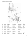
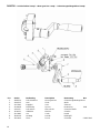
Spindelhuvud – Drill head – Bohrkopf
Pos Art.No. Benämning Description Benenung Not
1a. 2X08700 Spindelhus Spindle housing Spindelgehäuse manuell
1b. 2X08700-4 Spindelhus Spindle housing Spindelgehäuse M
2a. 2X08404 Växellåda Gear box Getriebekasten manuell
2b. 2X08404-M Växellåda Gear box Getriebekasten M
3. 2X08710 Spindelhylsa Spindle sleeve Spindelhülse
4a. 2X08752R Matningsaxel komp. Feed shaft compl. Vorschubwelle kompl. manuell
4b. 2X08514-1 Matningsaxel komp. Feed shaft compl. Vorschubwelle kompl. M
5. 2X08720-1R Snäckväxel Worm gear unit Schneckenwechsel
6. 2X0870X Frontkåpa Front cover Frontdeckel
7. 3P01407 Pinne Pin Stift CP 8x36
8. 4U08705 Elboxkåpa Electric box cover Elektrokastengehäuse
9. 3R00014 Ställbar låsspak Locking lever Sperrarm
10. 3S02556 Skruv M6S Screw Schraube 12x120
11. 3S02558 Skruv M6S Screw Schraube 12x130
12. 3M09122 Låsmutter Locking nut Sicherungsmutter M12
13. 3B04178 Bricka TRB Washer Scheibe 13x24x4

12
Växellåda – Gear box – Getriebegehäuse
Pos Art.No. Benämning Description Benennung Not
1. 2X08404-1 1:a axel kompl. 1:nd shaft complete 1:e Welle kompl.
2. 2X08404-2 2:a axel kompl. 2:nd shaft complete 2:e Welle kompl.
3a. 2X08404-3 3:e axel kompl. 3:rd shaft complete 3:e Welle kompl. manuell
3b. 2X08404-5 3:e axel kompl. 3:rd shaft complete 3:e Welle kompl. M
4a. 2X08422 Växellådshus kpl. Gear box complete Getriebekasten manuell
4b. 2X08422-1 Växellådshus kpl. Gear box complete Getriebekasten M
5. 4B00174 Styrring Ring Ring
6. 4B00173 Styrring Ring Ring
7. 2X08536 Skiftarm Gear selector arm Schaltarm
8. 4RS0653-1 Växelspak Gear lever Schalthebel
9. 4C02921 Fjäder Gear Feder
10. 3T04028 Stålkula Steel ball Schaltgriff
13. 4T04168 Skiftstift Shift pin Stift

13
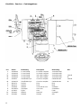
Motoraxel – Engine shaft – Motorwelle
Pos Art.No. Benämning Description Benennung Not
1. 4B00137 Lock Washer Scheibe
2. 3L11003 Enrad spårkullager Ball bearing Kugellager 6203
3. 2H07969 Kugghjul Gear Zahnrad 15-1,5
4. 2D17014 Distanshylsa Spacing sleeve Distanzhülse 17x14
5. 2H07972 Kugghjul Gear Zahnrad 39-1,5
6. 2D17002 Distanshylsa Spacing sleeve Distanzhülse 17x2
7. 3L11003 Enrad spårkullager Ball bearing Kugellager 6203
8. 4B00137 Lock Washer Scheibe
9. 3K00184 Kil Key Keil 5x5x14
10. 3K00187 Kil Key Keil 5x5x20
11. 4X08405 Motoraxel Rotor shaft Rotorwelle
12. 4F06203 Bricka Washer Scheibe FB 6203
13. 3L11003 Enrad spårkullager Ball bearing Kugellager 6203
14. 2N01889 Lagerlock Bearing cover Lagerdeckel B-1889
15. 4B00175 Vinghjul Fan Ventilator B-175
16. 2B03449 Bricka Washer Scheibe C-3449
17. 4B01890 Fläktkåpa Fan cover Ventilatordeckel C-1890
18. 3E81100 Stator 80/2-4-70 Stator 80/2-4-70 Stator 80/2-4-70 120-575V

14
2:a axel – 2:nd shaft – 2:e Welle
Pos Art.No. Benämning Description Benennung Not
1. 4B00138 Lock Washer Scheibe C-138
2. 3L11003 Enrad spårkullager Ball bearing Kugellager 6203
3. 2D00009 Distanshylsa Spacing sleeve Distanzhülse 17x3,5
4. 2H07971 Kugghjul Gear Zahnrad 32-2
5. 2D17038 Distanshylsa Spacing sleeve Distanzhülse 17x38
6. 2H07970 Kugghjul Gear Zahnrad 15-2
7. 2D00013 Distanshylsa Spacing sleeve Distanzhülse 17x5
8. 2A04871 2:a axel 2:nd shaft 2:e Welle C-4871
9. 3K01187 Kil Key Keil 5x5x20
10. 2T06615 Övre kil Key Keil C-6615
11. 2X08408R Kugghjul kompl. Gear complete Zahnrad kompl. 64-1,5
12. 2T04254 Kopplingsklo Clutch Kupplung C-4254
13. 2X08406R Kugghjul kompl. Gear complete Zahnrad kompl. 40-1,5
14. 2D00009 Distanshylsa Spacing sleeve Distanzhülse 17x3,5
15. 3L11003 Enrad spårkullager Ball bearing Kugellager 6203
16. 4B00138 Lock Cover Deckel C-138

15
3:e axel – 3:rd shaft – 3:e Welle
Pos Art. No. Benämning Description Benennung Not
1. 4B00138 Lock Cover Deckel C-138
2. 3L16002 Enrad spårkullager Ball bearing Kugellager 6302
3. 2D15002 Distanshylsa Spacing sleeve Distanzhülse 15x2
4. 3C01117 Spårring Circlip Führungsring SgA 15
5. 2X08413R Kugghjul kompl. Gear complete Zahnrad kompl. 32-2
6. 2T04254 Kopplingsklo Clutch Kupplung C 4254
7. 2X08411R Kugghjul kompl. Gear complete Zahnrad kompl. 49-2
8. 2D00006 Distanshylsa Spacing sleeve Distanzhülse 17x31,5
9. 3L11003 Enrad spårkullager Ball bearing Kugellager 6203
10. 4B00137 Lock Cover Deckel C-137
11. 2T06615 Övre kil Key Keil C-6615
12. 2A08410 3:e axel 3:rd shaft 3:e Welle B-8410
13a. 2D00011 Distanshylsa Spacer Distanzhülse 17x4,5, 2 st/pcs
13b. 2D00009 Distanshylsa Spacer Distanzhülse 17x3,5, 1 st/pc
14. 2HSB7501-1 Kugghjul Gear wheel Zahnrad 18-1,5
15. 2X08558 Mellanhjul kompl. Gear complete feed Zahnrad kompl. Vorsch.
16. 4D12006 Dist.hylsa Spacer Distanzhülse 12x6,5
17. 3C02131 Spårring Circlip Sicherungsring SGH32, 2st/pcs
18. 3L13001 Kullager Bearing Kugellager 6201 2Z
19. 3C01114 Spårring Circlip Sicherrungsring SGA 12
20. 2A08441 Axel till mellanhjul Feed gear shaft Welle Vorschubzahnrad

16
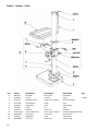
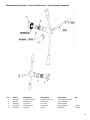
Pelare – Column – Säule
Pos Art.No. Benämning Description Benennung Not
1. 1B03013 Fotplatta Base plate Fussplatte
2. 4X08300 Pelare Column Säule L=1500
3. 2X08723 Bordarm kompl. Table arm complete Tischarm kompl.
4. 2WS1231 Fyrkantsbord Table Tisch
5. 2X08445 Kuggstång Rack Zahnstange
6. 2T07146 Tapp Pin Zapf
7. 2Y08723 Bordarm Table arm Tischarm
8. 2X08720-1R Snäckväxel kompl. Worm gear complete Schneckengetriebe kompl.
16. 2N00186R Nedre ring Lower ring Unterer Ring
17. 2I03598 Kuggstång Rack Zahnstange
18. 2N03668R Övre ring Upper ring Oberer Ring

17
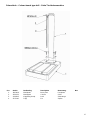
Pelare bänk – Column bench type drill – Säule Tischbohrmaschine
Pos Art.No. Benämning Description Benennung Not
1. 1B03016 Bänkplatta Base plate Fussplatte
2. 4ZS1232 Bänkpelare Column Säule
3. 2X08545 Kuggstång kompl. Rack Zahnstange
4. 2T07146 Tapp Pin Zapfen

18
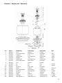
2X08720 – Snäckväxelhus kompl. – Worm gear box compl. – Schneckengetriebegehäuse kompl.
Pos Art.No. Benämning Description Benennung Not
1. 2N08720 Snäckväxelhus Worm gear box Schneckengetriebegehäuse
2. 2A08725 Axel Shaft Welle
3. 2HS1201 Kugghjul Gear Zahnrad
4. 2D20008 Distansring Spacer Distanzring 20x8
5. 2IS1203 Snäckskruv Worm shaft Schneckenwelle
6. 3L00021 Glidbricka Washer Scheibe
7. 2RS1182 Vev Crank Kurbel
8. 3R01106 Handtag Handle Ballengriff
9. 3S04444 Skruv Screw Schraube SK6SS 8x8

19
Matningsaxel (manuell) – Feed shaft (manual) – Vorschubwelle (manuell)
Pos Art.No. Benämning Description Benennung Not
1. 4XS2150 Fjäderhus kompl. Spring housing cpl. Federgehäuse kompl.
2. 2I08752 Matningsaxel Feed shaft Vorschubwelle
3. 4S04211 Tappskruv Pin screw Zapfschraube
4. 2E08758 Matningsspak Feed lever Vorschubhebel 3 st/pcs
5. 3R04004 Handtag Handle Ballengriff 3 st/pcs

20
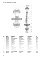
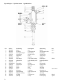
Spindelhylsa – Spindle sleeve – Spindelhülse
Pos Art.No. Benämning Description Benennung Not
1. 3M06005 Mutter Nut Mutter MK 5
2. 4B00155 Låsbricka Locking washer Sicherungsscheibe
3. 3L15005 Enrad.spårkullager Ball bearing Kugellager 6205
4. 2G08710 Spindelhylsa Spindle sleeve Spindelhülse
5. 2I08753 Kuggstång Rack Zahnstange
6. 4B03769 Bricka Washer Scheibe
7. 3L51006 Kon.rullager Taper roller bearing Rollenlager 30206
8. 2TS1106 Rullagerlock Roller bearing cover Rollenlagerdeckel
9. 2T08386 Kil Key Keil
10. 2A08418-1R Borrspindel Spindle Bohrspindel
11. 2T08593 Distanshylsa Spacing sleeve Distanzhülse
12. 3B06003 Bricka Washer Scheibe
13. 2T08547 Anslag Stop Anschlag
14. 3S08622 Skruv Screw Schraube P6SS 16x25
15. 2T08714 Klämback Collet jaw Klemmbacke
16. 2A08755 Djupmåttstång Depth gauge rod Tiefenmassstange
17. 2T08757 Stopp för matning Stop Anschlag
18. 3R00002 Handtag Locking lever Klemmhebel M6x16
19. 3C01114 Spårring Circlip Führungsring SgA12

21
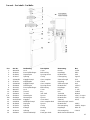
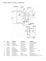
2X08705 – Ellåda – Electric Box – Elektrokasten
Pos Art.Nr. Benämning Description Benennung
1. 4U08705 Elboxkåpa Electric box cover Elektrokastengehäuse
2. 2L08712 Ankarsken Rail anchor Schienenklemme
3. 3E10600 Motorskydd Motor protector Motorschutz
4. 2E08713 Elboxdistanspinne Electric box Elektrokasten
distance tube Abstandstift
5. 4L08706 Fästplåt Anchor plate Halteblech
6. 4L09711-1 Elboxpanel Electric box plate Elektrokastenschild
7. 3E16227 Nödstoppknapp Emergency stop Notstopp
8. 3T18003 Svampgummilist Rubber moulding Gummifassung 15x8
9. 3E06016 Handpolomkopplare Pole reverser Polumschalter
10. 3E19083 Kontramutter Nut Mutter
11. 3E19225 Förskruvning Nipple Verschraubung
13. 3E10610 Undersp.utlösare Under volt release Unterspannungsauslöser
14. 4L09711-2 Elboxpanel revers. Electric box plate rev. Elektrokastenschild rev. (Alternativ)
Page is loading ...
Page is loading ...
Page is loading ...
-
 1
1
-
 2
2
-
 3
3
-
 4
4
-
 5
5
-
 6
6
-
 7
7
-
 8
8
-
 9
9
-
 10
10
-
 11
11
-
 12
12
-
 13
13
-
 14
14
-
 15
15
-
 16
16
-
 17
17
-
 18
18
-
 19
19
-
 20
20
-
 21
21
-
 22
22
-
 23
23
-
 24
24


JET 354029 User manual
- Category
- Toys
- Type
- User manual
Ask a question and I''ll find the answer in the document
Finding information in a document is now easier with AI
in other languages
- Deutsch: JET 354029 Benutzerhandbuch
- svenska: JET 354029 Användarmanual
Related papers
Other documents
-
 Bilora 199 Datasheet
-
Parkside PDSS 310 A1 Operation and Safety Notes
-
Ferm fag 180 Owner's manual
-
Parkside PDMH 4500 A2 Original Operation Manual
-
-
-
-
Kress 1055 HTC Datasheet
-
Mafell ZK 115 Ec Operating instructions
-
