ASROCK A55M-HVS Quick start guide
- Category
- Motherboards
- Type
- Quick start guide

1
ASRock A55M-HVS Motherboard
English
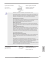
Copyright Notice:
No part of this installation guide may be reproduced, transcribed, transmitted, or trans-
lated in any language, in any form or by any means, except duplication of documentation
by the purchaser for backup purpose, without written consent of ASRock Inc.
Products and corporate names appearing in this guide may or may not be registered
trademarks or copyrights of their respective companies, and are used only for identica-
tion or explanation and to the owners’ benet, without intent to infringe.
Disclaimer:
Specications and information contained in this guide are furnished for informational use
only and subject to change without notice, and should not be constructed as a commit-
ment by ASRock. ASRock assumes no responsibility for any errors or omissions that may
appear in this guide.
With respect to the contents of this guide, ASRock does not provide warranty of any kind,
either expressed or implied, including but not limited to the implied warranties or condi-
tions of merchantability or tness for a particular purpose. In no event shall ASRock, its
directors, ofcers, employees, or agents be liable for any indirect, special, incidental, or
consequential damages (including damages for loss of prots, loss of business, loss of
data, interruption of business and the like), even if ASRock has been advised of the pos-
sibility of such damages arising from any defect or error in the guide or product.
This device complies with Part 15 of the FCC Rules. Operation is subject to the following
two conditions:
(1) this device may not cause harmful interference, and
(2) this device must accept any interference received, including interference that
may cause undesired operation.
CALIFORNIA, USA ONLY
The Lithium battery adopted on this motherboard contains Perchlorate, a toxic substance
controlled in Perchlorate Best Management Practices (BMP) regulations passed by the
California Legislature. When you discard the Lithium battery in California, USA, please
follow the related regulations in advance.
“Perchlorate Material-special handling may apply, see
www.dtsc.ca.gov/hazardouswaste/perchlorate”
ASRock Website: http://www.asrock.com
Published August 2011
Copyright
©
2011 ASRock INC. All rights reserved.

2
ASRock A55M-HVS Motherboard
English
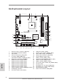
Motherboard Layout
1 ATX 12V Power Connector (ATX12V1) 16 COM Port Header (COM1)
2 CPU Heatsink Retention Module 17 System Panel Header (PANEL1, White)
3 CPU Socket 18 Clear CMOS Jumper (CLRCMOS1)
4 CPU Fan Connector (CPU_FAN1) 19 Chassis Fan Connector (CHA_FAN1)
5 2 x 240-pin DDR3 DIMM Slots 20 Infrared Module Header (IR1)
(Dual Channel: DDR3_A1, DDR3_B1; Blue) 21 USB 2.0 Header (USB6_7, Blue)
6 ATX Power Connector (ATXPWR1) 22 Consumer Infrared Module Header (CIR1)
7 SATA2 Connector (SATA_3, Blue) 23 USB 2.0 Header (USB8_9, Blue)
8 SATA2 Connector (SATA_5, Blue) 24 USB 2.0 Header (USB10_11, Blue)
9 SATA2 Connector (SATA_6, Blue) 25 Front Panel Audio Header (HD_AUDIO1, White)
10 SATA2 Connector (SATA_4, Blue) 26 PCI Slot (PCI1)
11 SATA2 Connector (SATA_2, Blue) 27 PCI Express 2.0 x16 Slot (PCIE2; Blue)
12 SATA2 Connector (SATA_1, Blue) 28 PCI Express 2.0 x1 Slot (PCIE1; White)
13 Chassis Speaker Header (SPEAKER 1, White) 29 SPI Flash Memory (32Mb)
14 Southbridge Controller 30 Power Fan Connector (PWR_FAN1)
15 Print Port Header (LPT1, White)
Supe r
I/O
CM OS
BA TT ER Y
ATXPWR1
AMD
A55 FCH
(Hudson-D2)
Chipset
COM1
PCIE1
PCI1
LAN
AUDI O
CODE C
1
CLR CMO S1
1
CPU _FAN1
HDLED R ESET
PLED P WRBT N
1
PANEL 1
CHA _FAN 1
SPEA KER 1
1
HD_A UDIO 1
1
22.6cm (8.9-in)
21.6cm (8.5-in)
6
7
1
2 4
3
5
8
9
10
11
12
13
14
15
16
17
181920
2122
23
24
25
26
27
28
29
32Mb
BIOS
IR1
1
PCIE2
FSB80 0
DDR3_A1 (64 bi t , 2 40-p in module)
DDR3_B1 (64 bi t , 2 40-p in module)
SATA_2
HDMI 1
Top:
LINE IN
Cen t er:
FRON T
Bot t om:
MIC IN
RJ-45 LAN
1
1
1
USB 6 _7
USB 8 _9
USB 1 0_11
PWR_ FAN1
A55M-HVS
ErP/EuP Ready
Designed in Taipei
RoHS
DDR3 2400+
DX11
USB 2 .0
T: US B0
B: USB 1
CIR1
1
SOCKET FM1
SATA_1
SATA_4
SATA_3
1
LPT 1
ATX12 V1
HDMI 1.4a
PS2
Mou se
PS2
Key bo ar d
VGA1
USB 2 .0
T: US B2
B: USB 3
30
SATA_6
SATA_5
USB 2 .0
T: US B4
B: USB 5
Dual Graphics
X
Fast USB

3
ASRock A55M-HVS Motherboard
English
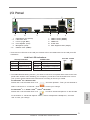
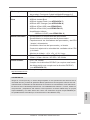
I/O Panel
* There are two LED next to the LAN port. Please refer to the table below for the LAN port LED
indications.
LAN Port LED Indications
Activity/Link LED SPEED LED
Status Description Status Description
Off No Link Off 10Mbps connection
Blinking Data Activity Orange 100Mbps connection
On Link Green 1Gbps connection
1 PS/2 Mouse Port (Green) 7 USB 2.0 Ports (USB45)
* 2 LAN RJ-45 Port 8 USB 2.0 Ports (USB23)
3 Line In (Light Blue) 9 HDMI Port
** 4 Front Speaker (Lime) 10 D-Sub Port
5 Microphone (Pink) 11 PS/2 Keyboard Port (Purple)
*** 6 USB 2.0 Ports (USB01)
LAN Port
ACT/LINK
LED
SPEED
LED
6
7
9
1011
1
2
4
3
5
8
** To enable Multi-Streaming function, you need to connect a front panel audio cable to the front
panel audio header. After restarting your computer, you will nd “VIA HD Audio Deck” tool on
your system. Please follow below instructions according to the OS you install.
For Windows
®
XP / XP 64-bit OS:
Please click “VIA HD Audio Deck” icon , and click “Speaker”. Then you are allowed to
select “2 Channel” or “4 Channel”. Click “Power” to save your change.
For Windows
®
7 / 7 64-bit / Vista
TM
/ Vista
TM
64-bit OS:
Please click “VIA HD Audio Deck” icon , and click “Advanced Options” on the left side
on the bottom. In “Advanced Options” screen, select “Independent Headphone”, and click
“OK” to save your change.

4
ASRock A55M-HVS Motherboard
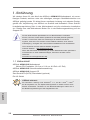
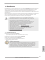
1. Introduction
Thank you for purchasing ASRock A55M-HVS motherboard, a reliable motherboard
produced under ASRock’s consistently stringent quality control. It delivers excellent
performance with robust design conforming to ASRock’s commitment to quality and
endurance.
This Quick Installation Guide contains introduction of the motherboard and step-by-
step installation guide. More detailed information of the motherboard can be found
in the user manual presented in the Support CD.
Because the motherboard specications and the BIOS software might be
updated, the content of this manual will be subject to change without no-
tice. In case any modications of this manual occur, the updated version
will be available on ASRock website without further notice. You may nd
the latest VGA cards and CPU support lists on ASRock website as well.
ASRock website http://www.asrock.com
If you require technical support related to this motherboard, please visit
our website for specic information about the model you are using.
www.asrock.com/support/index.asp
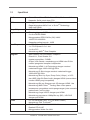
1.1 Package Contents
ASRock A55M-HVS Motherboard
(Micro ATX Form Factor: 8.9-in x 8.5-in, 22.6 cm x 21.6 cm)
ASRock A55M-HVS Quick Installation Guide
ASRock A55M-HVS Support CD
2 x Serial ATA (SATA) Data Cables (Optional)
1 x I/O Panel Shield
ASRock Reminds You...
To get better performance in Windows
®
7 / 7 64-bit / Vista
TM
/ Vista
TM
64-
bit, it is recommended to set the BIOS option in Storage Conguration to
AHCI mode. For the BIOS setup, please refer to the “User Manual” in our
support CD for details.
English

5
ASRock A55M-HVS Motherboard
English
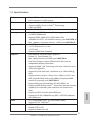
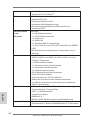
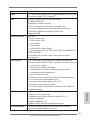
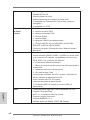
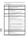
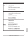
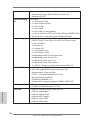
1.2 Specifications
Platform - Micro ATX Form Factor: 8.9-in x 8.5-in, 22.6 cm x 21.6 cm
- Solid Capacitor for CPU power
CPU - Support for Socket FM1 100W processors
- Supports AMD’s Cool ‘n’ Quiet
TM
Technology
- UMI-Link GEN2
Chipset - AMD A55 FCH (Hudson-D2)
Memory - Dual Channel DDR3 Memory Technology (see CAUTION 1)
- 2 x DDR3 DIMM slots
- Support DDR3 2400+(OC)/1866/1600/1333/
1066/800 non-ECC, un-buffered memory (see CAUTION 2)
- Max. capacity of system memory: 16GB (see CAUTION 3)
Expansion Slot - 1 x PCI Express 2.0 x16 slot
- 1 x PCI Express 2.0 x1 slot
- 1 x PCI slot
- Supports AMD Dual Graphics
Graphics - AMD Radeon HD 65XX/64XX graphics
- DirectX 11, Pixel Shader 5.0
- Max. shared memory 512MB (see CAUTION 4)
- Dual VGA Output: support HDMI and D-Sub ports by
independent display controllers
- Supports HDMI 1.4a Technology with max. resolution up to
1920x1200 @ 60Hz
- Supports D-Sub with max. resolution up to 1920x1600 @
60Hz
- Supports Auto Lip Sync, Deep Color (12bpc), xvYCC and
HBR (High Bit Rate Audio) with HDMI (Compliant HDMI
monitor is required) (see CAUTION 5)
- Supports Blu-ray Stereoscopic 3D with HDMI 1.4a
- Supports AMD Steady Video
TM
: New video post processing
capability for automatic jutter reduction on home/online
video
- Supports HDCP function with HDMI port
- Supports Full HD 1080p Blu-ray (BD) / HD-DVD playback
with HDMI port
Audio - 5.1 CH HD Audio (VIA
®
VT1705 Audio Codec)
- Supports THX TruStudio
TM
LAN - PCIE x1 Gigabit LAN 10/100/1000 Mb/s
- Realtek RTL8111E
- Supports Wake-On-LAN

6
ASRock A55M-HVS Motherboard
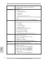
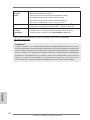
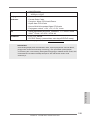
English
- Supports LAN Cable Detection
- Supports Energy Efcient Ethernet 802.3az
- Supports PXE
Rear Panel I/O I/O Panel
- 1 x PS/2 Mouse Port
- 1 x PS/2 Keyboard Port
- 1 x D-Sub Port
- 1 x HDMI Port
- 6 x Ready-to-Use USB 2.0 Ports
- 1 x RJ-45 LAN Port with LED (ACT/LINK LED and SPEED
LED)
- HD Audio Jack: Line in/Front Speaker/Microphone
Connector - 6 x SATA2 3.0 Gb/s connectors, support RAID (RAID 0,
RAID 1 and RAID 10), NCQ, AHCI and “Hot Plug” functions
- 1 x IR header
- 1 x CIR header
- 1 x Print port header
- 1 x COM port header
- CPU/Chassis/Power FAN connector
- 24 pin ATX power connector
- 8 pin 12V power connector
- Front panel audio connector
- 3 x USB 2.0 headers (support 6 USB 2.0 ports)
BIOS Feature - 32Mb AMI UEFI Legal BIOS with GUI support
- Supports “Plug and Play”
- ACPI 1.1 Compliance Wake Up Events
- Supports jumperfree
- SMBIOS 2.3.1 Support
- DRAM, VDDP, SB Voltage Multi-adjustment
Support CD - Drivers, Utilities, AntiVirus Software (Trial Version),
CyberLink MediaEspresso 6.5 Trial
Unique Feature - ASRock Extreme Tuning Utility (AXTU) (see CAUTION 6)
- ASRock Instant Boot
- ASRock Instant Flash (see CAUTION 7)
- ASRock APP Charger (see CAUTION 8)
- ASRock XFast USB (see CAUTION 9)
- ASRock XFast LAN (see CAUTION 10)
- Hybrid Booster:
- ASRock U-COP (see CAUTION 11)

7
ASRock A55M-HVS Motherboard
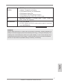
English
Hardware - CPU Temperature Sensing
Monitor - Chassis Temperature Sensing
- CPU/Chassis/Power Fan Tachometer
- CPU/Chassis Quiet Fan
- CPU/Chassis Fan Multi-Speed Control
- Voltage Monitoring: +12V, +5V, +3.3V, Vcore
OS - Microsoft
®
Windows
®
7 / 7 64-bit / Vista
TM
/ Vista
TM
64-bit / XP
SP3 / XP 64-bit compliant
Certications - FCC, CE, WHQL
- ErP/EuP Ready (ErP/EuP ready power supply is required)
(see CAUTION 12)
* For detailed product information, please visit our website: http://www.asrock.com
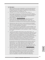
WARNING
Please realize that there is a certain risk involved with overclocking, including adjusting the
setting in the BIOS, applying Untied Overclocking Technology, or using the third-party over-
clocking tools. Overclocking may affect your system stability, or even cause damage to the
components and devices of your system. It should be done at your own risk and expense.
We are not responsible for possible damage caused by overclocking.

8
ASRock A55M-HVS Motherboard
English
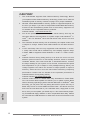
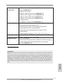
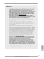
CAUTION!
1. This motherboard supports Dual Channel Memory Technology. Before
you implement Dual Channel Memory Technology, make sure to read the
installation guide of memory modules on page 12 for proper installation.
2. Whether 2400/1866/1600MHz memory speed is supported depends on
the CPU you adopt. If you want to adopt DDR3 2400/1866/1600 memory
module on this motherboard, please refer to the memory support list on
our website for the compatible memory modules.
ASRock website http://www.asrock.com
3. Due to the operating system limitation, the actual memory size may be
less than 4GB for the reservation for system usage under Windows
®
7 /
Vista
TM
/ XP. For Windows
®
64-bit OS with 64-bit CPU, there is no such
limitation.
4. The maximum shared memory size is dened by the chipset vendor and
is subject to change. Please check AMD website for the latest informa-
tion.
5. xvYCC and Deep Color are only supported under Windows
®
7 64-bit /
7. Deep Color mode will be enabled only if the display supports 12bpc
in EDID. HBR is supported under Windows
®
7 64-bit / 7 / Vista
TM
64-bit /
Vista
TM
.
6. ASRock Extreme Tuning Utility (AXTU) is an all-in-one tool to ne-tune
different system functions in a user-friendly interface, which is including
Hardware Monitor, Fan Control and IES. In Hardware Monitor, it shows
the major readings of your system. In Fan Control, it shows the fan speed
and temperature for you to adjust. In IES (Intelligent Energy Saver), the
voltage regulator can reduce the number of output phases to improve
efficiency when the CPU cores are idle without sacrificing computing
performance. Please visit our website for the operation procedures of
ASRock Extreme Tuning Utility (AXTU).
ASRock website: http://www.asrock.com
7. ASRock Instant Flash is a BIOS ash utility embedded in Flash ROM.
This convenient BIOS update tool allows you to update system BIOS
without entering operating systems rst like MS-DOS or Windows
®
. With
this utility, you can press <F6> key during the POST or press <F2> key to
BIOS setup menu to access ASRock Instant Flash. Just launch this tool
and save the new BIOS le to your USB ash drive, oppy disk or hard
drive, then you can update your BIOS only in a few clicks without prepar-
ing an additional oppy diskette or other complicated ash utility. Please
be noted that the USB ash drive or hard drive must use FAT32/16/12 le
system.

9
ASRock A55M-HVS Motherboard
English
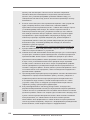
8. If you desire a faster, less restricted way of charging your Apple devices,
such as iPhone/iPod/iPad Touch, ASRock has prepared a wonderful solu-
tion for you - ASRock APP Charger. Simply installing the APP Charger
driver, it makes your iPhone charged much quickly from your computer
and up to 40% faster than before. ASRock APP Charger allows you to
quickly charge many Apple devices simultaneously and even supports
continuous charging when your PC enters into Standby mode (S1), Sus-
pend to RAM (S3), hibernation mode (S4) or power off (S5). With APP
Charger driver installed, you can easily enjoy the marvelous charging
experience than ever.
ASRock website: http://www.asrock.com/Feature/AppCharger/index.asp
9. ASRock XFast USB can boost USB storage device performance. The
performance may depend on the property of the device.
10. ASRock XFast LAN provides a faster internet access, which includes be-
low benets. LAN Application Prioritization: You can congure your appli-
cation priority ideally and/or add new programs. Lower Latency in Game:
After setting online game priority higher, it can lower the latency in game.
Traffic Shaping: You can watch Youtube HD video and download files
simultaneously. Real-Time Analysis of Your Data: With the status window,
you can easily recognize which data streams you are currently transfer-
ring.
11. While CPU overheat is detected, the system will automatically shutdown.
Before you resume the system, please check if the CPU fan on the moth-
erboard functions properly and unplug the power cord, then plug it back
again. To improve heat dissipation, remember to spray thermal grease
between the CPU and the heatsink when you install the PC system.
12. EuP, stands for Energy Using Product, was a provision regulated by Eu-
ropean Union to dene the power consumption for the completed system.
According to EuP, the total AC power of the completed system shall be
under 1.00W in off mode condition. To meet EuP standard, an EuP ready
motherboard and an EuP ready power supply are required. According to
Intel’s suggestion, the EuP ready power supply must meet the standard
of 5v standby power efciency is higher than 50% under 100 mA current
consumption. For EuP ready power supply selection, we recommend you
checking with the power supply manufacturer for more details.

10
ASRock A55M-HVS Motherboard
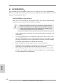
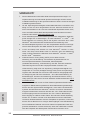
2. Installation
This is a Micro ATX form factor (8.9-in x 8.5-in, 22.6 cm x 21.6 cm) motherboard.
Before you install the motherboard, study the conguration of your chassis to ensure
that the motherboard ts into it.
Pre-installation Precautions
Take note of the following precautions before you install motherboard
components or change any motherboard settings.
Before you install or remove any component, ensure that the
power is switched off or the power cord is detached from the
power supply. Failure to do so may cause severe damage to the
motherboard, peripherals, and/or components.
1. Unplug the power cord from the wall socket before touching any
component.
2. To avoid damaging the motherboard components due to static elec-
tricity, NEVER place your motherboard directly on the carpet or the
like. Also remember to use a grounded wrist strap or touch a safety
grounded object before you handle components.
3. Hold components by the edges and do not touch the ICs.
4. Whenever you uninstall any component, place it on a grounded anti-
static pad or in the bag that comes with the component.
5. When placing screws into the screw holes to secure the mother-
board to the chassis, please do not over-tighten the screws! Doing
so may damage the motherboard.
English

11
ASRock A55M-HVS Motherboard
English
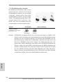
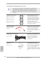
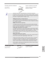
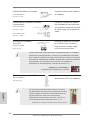
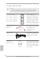
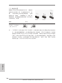
2.1 CPU Installation
Step 1. Unlock the socket by lifting the lever up to a 90
o
angle.
Step 2. Position the CPU directly above the socket such that the CPU corner with
the golden triangle matches the socket corner with a small triangle.
Step 3. Carefully insert the CPU into the socket until it ts in place.
The CPU ts only in one correct orientation. DO NOT force the CPU
into the socket to avoid bending of the pins.
Step 4. When the CPU is in place, press it rmly on the socket while you push
down the socket lever to secure the CPU. The lever clicks on the side tab
to indicate that it is locked.
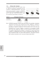
2.2 Installation of CPU Fan and Heatsink
After you install the CPU into this motherboard, it is necessary to install a
larger heatsink and cooling fan to dissipate heat. You also need to spray
thermal grease between the CPU and the heatsink to improve heat dis-
sipation. Make sure that the CPU and the heatsink are securely fastened
and in good contact with each other. Then connect the CPU fan to the
CPU FAN connector (CPU_FAN1, see Page 2, No. 4). For proper instal-
lation, please kindly refer to the instruction manuals of the CPU fan and
the heatsink.
STEP 1:
Lift Up The Socket Lever
STEP 2 / STEP 3:
Match The CPU Golden Triangle
To The Socket Corner Small
Triangle
STEP 4:
Push Down And Lock
The Socket Lever
CPU Golden Triangle
Lever 90° Up
Socket Corner Small
Triangle

12
ASRock A55M-HVS Motherboard
English
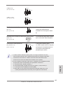
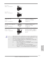
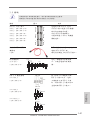
2.3 Installation of Memory Modules (DIMM)
This motherboard provides two 240-pin DDR3 (Double Data Rate 3) DIMM slots,
and supports Dual Channel Memory Technology. For dual channel configuration,
you always need to install two identical (the same brand, speed, size and chip-
type) memory modules in the DDR3 DIMM slots to activate Dual Channel Memory
Technology. Otherwise, it will operate at single channel mode.
1. It is not allowed to install a DDR or DDR2 memory module into
DDR3 slot;otherwise, this motherboard and DIMM may be
damaged.
2. If you install only one memory module or two non-identical
memory modules, it is unable to activate the Dual Channel
Memory Technology.
Installing a DIMM
Please make sure to disconnect power supply before adding or
removing DIMMs or the system components.
Step 1. Unlock a DIMM slot by pressing the retaining clips outward.
Step 2. Align a DIMM on the slot such that the notch on the DIMM matches the
break on the slot.
The DIMM only ts in one correct orientation. It will cause permanent
damage to the motherboard and the DIMM if you force the DIMM into the slot
at incorrect orientation.
Step 3. Firmly insert the DIMM into the slot until the retaining clips at both ends
fully snap back in place and the DIMM is properly seated.

13
ASRock A55M-HVS Motherboard
English
2.4 Expansion Slots (PCI and PCI Express Slots)
There are 1 PCI slot and 2 PCI Express slots on this motherboard.
PCI Slot: PCI slot is used to install expansion cards that have the 32-bit PCI
interface.
PCIE Slots:
PCIE1 (PCIE x1 slot; White) is used for PCI Express cards with x1 lane
width cards, such as Gigabit LAN card and SATA2 card.
PCIE2 (PCIE x16 slot; Blue) is used for PCI Express x16 lane width
graphics cards.
Installing an expansion card
Step 1. Before installing the expansion card, please make sure that the power
supply is switched off or the power cord is unplugged. Please read the
documentation of the expansion card and make necessary hardware
settings for the card before you start the installation.
Step 2. Remove the system unit cover (if your motherboard is already installed
in a chassis).
Step 3. Remove the bracket facing the slot that you intend to use. Keep the
screws for later use.
Step 4. Align the card connector with the slot and press rmly until the card is
completely seated on the slot.
Step 5. Fasten the card to the chassis with screws.
Step 6. Replace the system cover.

14
ASRock A55M-HVS Motherboard
English
2.5 AMD Dual Graphics Operation Guide
This motherboard supports AMD Dual Graphics feature. AMD Dual Graphics brings
multi-GPU performance capabilities by enabling an AMD A55 FCH (Hudson-D2)
integrated graphics processor and a discrete graphics processor to operate
simultaneously with combined output to a single display for blisteringly-fast frame
rates. Currently, AMD Dual Graphics Technology is only supported with Windows
®
7
OS, and is not available with Windows
®
Vista
TM
/ XP OS.
What does an AMD Dual Graphics system include?
An AMD Dual Graphics system includes an AMD Radeon HD 65XX/64XX graphics
processor and a motherboard based on an AMD A55 FCH (Hudson-D2) integrated
chipset, all operating in a Windows
®
7 environment. Please refer to below PCI
Express graphics card support list for AMD Dual Graphics. For the future update of
more compatible PCI Express graphics cards, please visit AMD website for further
information.
Chipset Model Driver
AMD RADEON HD6670 ASUS DIS-PCIE2.1-ASUS-HDMI-EAH6670-DI-1GD3/1G-DDR3 8.863
AMD RADEON HD6570 MSI DIS-PCIE2.1-MSI-HDMI-R6570-MD1GD3-LP/1G-DDR3 8.863
AMD RADEON HD6450 MSI DIS-PCIE2.1-MSI-HDMI-R6450-MD1GD3-LP/1G-DDR3 8.863
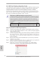
Enjoy the benefit of AMD Dual Graphics
Step 1. Please keep the default UEFI setting of “Dual Graphics“ option on [Auto].
Step 2. Install one AMD RADEON HD6670 / 6570 / 6450 PCI Express graphics
card to PCIE2 slot (blue).
Step 3. Connect the monitor cable to the onboard VGA port. Please be noted that
the current VGA driver / VBIOS can allow Dual Graphics output from on-
board display only. For any future update, please refer to our website for
further information.
Step 4. Boot into OS. Please remove the AMD driver if you have any VGA driver
installed in your system.
Step 5. Install the onboard VGA driver from our support CD to your system for
both the onboard VGA and the discrete graphics card.
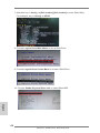
Step 6. Restart your computer. Right-click the desktop. Click “AMD VISION
Engine Control Center” to enter AMD VISION Engine Control Center.

15
ASRock A55M-HVS Motherboard
English
* Dual Graphics appearing here is a registered trademark of AMD Technologies Inc., and is
used only for identication or explanation and to the owners’ benet, without intent to infringe.
* For further information of AMD Dual Graphics technology, please check AMD website for up
dates and details.
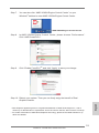
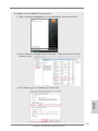
Step 9. Click “Enable CrossFire
TM
” and click “Apply“ to save your change.
Step 10. Reboot your system. Then you can freely enjoy the benet of Dual
Graphics feature.
AMD VISION Engine Control Center
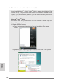
Step 7. You can also click “AMD VISION Engine Control Center” on your
Windows
®
taskbar to enter AMD VISION Engine Control Center.
Step 8. In AMD VISION Engine Control Center, please choose “Performance”.
Click “AMD CrossFire
TM
”.

16
ASRock A55M-HVS Motherboard
English
2. If you have installed onboard VGA driver from our support CD to your system
already, you can freely enjoy the benets of dual monitor function after your
system boots. If you haven’t installed onboard VGA driver yet, please install
onboard VGA driver from our support CD to your system and restart your
computer.
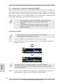
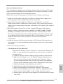
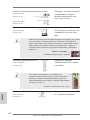
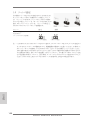
2.6 Dual Monitor and Surround Display Features
Dual Monitor Feature
This motherboard supports dual monitor feature. With the internal VGA output sup-
port (D-Sub and HDMI), you can easily enjoy the benets of dual monitor feature
without installing any add-on VGA card to this motherboard. This motherboard also
provides independent display controllers for D-Sub and HDMI to support dual VGA
output so that D-sub and HDMI can drive same or different display contents.
To enable dual monitor feature, please follow the below steps:
1. Connect D-Sub monitor cable to D-Sub port on the I/O panel, or connect
HDMI monitor cable to HDMI port on the I/O panel.
HDMI port
D-Sub port

17
ASRock A55M-HVS Motherboard
English
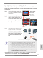
Surround Display Feature
This motherboard supports surround display upgrade. With the internal VGA output
support (D-Sub and HDMI) and external add-on PCI Express VGA cards, you can
easily enjoy the benets of surround display feature.
Please refer to the following steps to set up a surround display environment:
1. Install the PCI Express VGA cards on PCIE2 slot. Please refer to page 13 for
proper expansion card installation procedures for details.
2. Connect D-Sub monitor cable to D-Sub port on the I/O panel, or connect
HDMI monitor cable to HDMI port on the I/O panel. Then connect other monitor
cables to the corresponding connectors of the add-on PCI Express VGA cards on
PCIE2 slot.
3. Boot your system. Press <F2> or <Del> to enter UEFI setup. Enter “Share
Memory” option to adjust the memory capability to [32MB], [64MB], [128MB],
[256MB] or [512MB] to enable the function of D-sub. Please make sure that
the value you select is less than the total capability of the system memory. If you
do not adjust the UEFI setup, the default value of “Share Memory”, [Auto], will
disable D-Sub function when the add-on VGA card is inserted to this
motherboard.
4. Install the onboard VGA driver and the add-on PCI Express VGA card driver to
your system. If you have installed the drivers already, there is no need to install
them again.
5. Set up a multi-monitor display.
For Windows
®
XP / XP 64-bit OS:
Right click the desktop, choose “Properties”, and select the “Settings” tab
so that you can adjust the parameters of the multi-monitor according to
the steps below.
A. Click the “Identify” button to display a large number on each monitor.
B. Right-click the display icon in the Display Properties dialog that you
wish to be your primary monitor, and then select “Primary”. When
you use multiple monitors with your card, one monitor will always be
Primary, and all additional monitors will be designated as Secondary.
C. Select the display icon identied by the number 2.
D. Click “Extend my Windows desktop onto this monitor”.
E. Right-click the display icon and select “Attached”, if necessary.
F. Set the “Screen Resolution” and “Color Quality” as appropriate for the
second monitor. Click “Apply” or “OK” to apply these new values.
G. Repeat steps C through E for the diaplay icon identied by the number
one to four.

18
ASRock A55M-HVS Motherboard
English
For Windows
®
7 / 7 64-bit / Vista
TM
/ Vista
TM
64-bit OS:
Right click the desktop, choose “Personalize”, and select the “Display
Settings” tab so that you can adjust the parameters of the multi-monitor
according to the steps below.
A. Click the number ”2” icon.
B. Click the items “This is my main monitor” and “Extend the desktop onto
this monitor”.
C. Click “OK” to save your change.
D. Repeat steps A through C for the display icon identied by the number
three to four.
6. Use Surround Display. Click and drag the display icons to positions representing
the physical setup of your monitors that you would like to use. The placement
of display icons determines how you move items from one monitor to another.
HDCP Function
HDCP function is supported on this motherboard. To use HDCP
function with this motherboard, you need to adopt the monitor
that supports HDCP function as well. Therefore, you can enjoy
the superior display quality with high-denition HDCP
encryption contents. Please refer to below instruction for more
details about HDCP function.
What is HDCP?
HDCP stands for High-Bandwidth Digital Content Protection,
a specication developed by Intel
®
for protecting digital
entertainment content that uses the DVI interface. HDCP is a
copy protection scheme to eliminate the possibility of
intercepting digital data midstream between the video source,
or transmitter - such as a computer, DVD player or set-top box -
and the digital display, or receiver - such as a monitor, television
or projector. In other words, HDCP specication is designed to
protect the integrity of content as it is being transmitted.
Products compatible with the HDCP scheme such as DVD
players, satellite and cable HDTV set-top-boxes, as well as few
entertainment PCs requires a secure connection to a compliant
display. Due to the increase in manufacturers employing HDCP
in their equipment, it is highly recommended that the HDTV or
LCD monitor you purchase is compatible.

19
ASRock A55M-HVS Motherboard
English
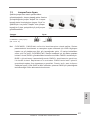
* ASRock Smart Remote is only supported by some of ASRock motherboards. Please refer to
ASRock website for the motherboard support list: http://www.asrock.com
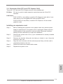
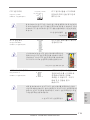
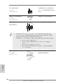
USB 2.0 header
(9-pin, blue)
CIR header
(4-pin, white)
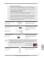
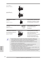
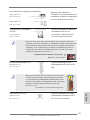
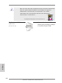
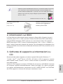
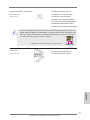
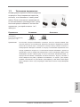
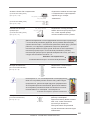
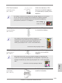
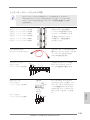
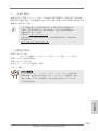
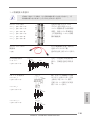
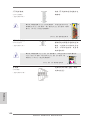
2.7 ASRock Smart Remote Installation Guide
ASRock Smart Remote is only used for ASRock motherboard with CIR header.
Please refer to below procedures for the quick installation and usage of ASRock
Smart Remote.
Step1. Find the CIR header located next
to the USB 2.0 header on ASRock
motherboard.
Step2. Connect the front USB cable to the
USB 2.0 header (as below, pin 1-5)
and the CIR header. Please make
sure the wire assignments and the
pin assignments are matched
correctly.
USB_PWR
P-
P+
GND
ATX+5VSB
IRRX
IRTX
GND
DUMMY
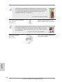
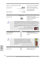
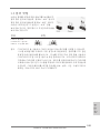
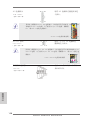
Step3. Install Multi-Angle CIR Receiver to
the front USB port. If Multi-Angle
CIR Receiver cannot successfully
receive the infrared signals from
MCE Remote Controller, please try
to install it to the other front USB
port.
3 CIR sensors in different angles
1. Only one of the front USB port can support CIR function. When the
CIR function is enabled, the other port will remain USB function.
2. Multi-Angle CIR Receiver is used for front USB only. Please do not
use the rear USB bracket to connect it on the rear panel. Multi-Angle
CIR Receiver can receive the multi-direction infrared signals (top,
down and front), which is compatible with most of the chassis on the
market.
3. The Multi-Angle CIR Receiver does not support Hot-Plug function.
Please install it before you boot the system.

20
ASRock A55M-HVS Motherboard
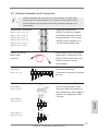
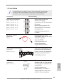
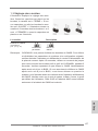
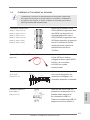
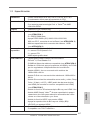
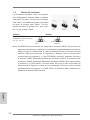
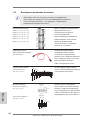
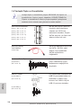
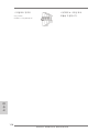
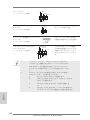
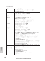
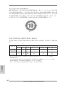
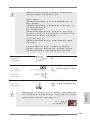
2.8 Jumpers Setup
The illustration shows how jumpers are
setup. When the jumper cap is placed on
pins, the jumper is “Short”. If no jumper cap
is placed on pins, the jumper is “Open”. The
illustration shows a 3-pin jumper whose
pin1 and pin2 are “Short” when jumper cap
is placed on these 2 pins.
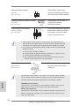
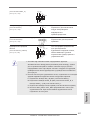
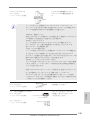
Jumper Setting Description
Clear CMOS Jumper
(CLRCMOS1)
(see p.2, No. 18)
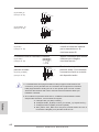
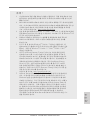
Note: CLRCMOS1 allows you to clear the data in CMOS. To clear and reset the
system parameters to default setup, please turn off the computer and unplug
the power cord from the power supply. After waiting for 15 seconds, use a
jumper cap to short pin2 and pin3 on CLRCMOS1 for 5 seconds. However,
please do not clear the CMOS right after you update the BIOS. If you need
to clear the CMOS when you just nish updating the BIOS, you must boot
up the system rst, and then shut it down before you do the clear-CMOS ac-
tion. Please be noted that the password, date, time, user default prole, 1394
GUID and MAC address will be cleared only if the CMOS battery is removed.
Clear CMOSDefault
English
Page is loading ...
Page is loading ...
Page is loading ...
Page is loading ...
Page is loading ...
Page is loading ...
Page is loading ...
Page is loading ...
Page is loading ...
Page is loading ...
Page is loading ...
Page is loading ...
Page is loading ...
Page is loading ...
Page is loading ...
Page is loading ...
Page is loading ...
Page is loading ...
Page is loading ...
Page is loading ...
Page is loading ...
Page is loading ...
Page is loading ...
Page is loading ...
Page is loading ...
Page is loading ...
Page is loading ...
Page is loading ...
Page is loading ...
Page is loading ...
Page is loading ...
Page is loading ...
Page is loading ...
Page is loading ...
Page is loading ...
Page is loading ...
Page is loading ...
Page is loading ...
Page is loading ...
Page is loading ...
Page is loading ...
Page is loading ...
Page is loading ...
Page is loading ...
Page is loading ...
Page is loading ...
Page is loading ...
Page is loading ...
Page is loading ...
Page is loading ...
Page is loading ...
Page is loading ...
Page is loading ...
Page is loading ...
Page is loading ...
Page is loading ...
Page is loading ...
Page is loading ...
Page is loading ...
Page is loading ...
Page is loading ...
Page is loading ...
Page is loading ...
Page is loading ...
Page is loading ...
Page is loading ...
Page is loading ...
Page is loading ...
Page is loading ...
Page is loading ...
Page is loading ...
Page is loading ...
Page is loading ...
Page is loading ...
Page is loading ...
Page is loading ...
Page is loading ...
Page is loading ...
Page is loading ...
Page is loading ...
Page is loading ...
Page is loading ...
Page is loading ...
Page is loading ...
Page is loading ...
Page is loading ...
Page is loading ...
Page is loading ...
Page is loading ...
Page is loading ...
Page is loading ...
Page is loading ...
Page is loading ...
Page is loading ...
Page is loading ...
Page is loading ...
Page is loading ...
Page is loading ...
Page is loading ...
Page is loading ...
Page is loading ...
Page is loading ...
Page is loading ...
Page is loading ...
Page is loading ...
Page is loading ...
Page is loading ...
Page is loading ...
Page is loading ...
Page is loading ...
Page is loading ...
Page is loading ...
Page is loading ...
Page is loading ...
Page is loading ...
Page is loading ...
Page is loading ...
Page is loading ...
Page is loading ...
Page is loading ...
Page is loading ...
Page is loading ...
Page is loading ...
Page is loading ...
Page is loading ...
Page is loading ...
Page is loading ...
Page is loading ...
Page is loading ...
Page is loading ...
Page is loading ...
Page is loading ...
Page is loading ...
Page is loading ...
Page is loading ...
Page is loading ...
Page is loading ...
Page is loading ...
Page is loading ...
Page is loading ...
Page is loading ...
Page is loading ...
-
 1
1
-
 2
2
-
 3
3
-
 4
4
-
 5
5
-
 6
6
-
 7
7
-
 8
8
-
 9
9
-
 10
10
-
 11
11
-
 12
12
-
 13
13
-
 14
14
-
 15
15
-
 16
16
-
 17
17
-
 18
18
-
 19
19
-
 20
20
-
 21
21
-
 22
22
-
 23
23
-
 24
24
-
 25
25
-
 26
26
-
 27
27
-
 28
28
-
 29
29
-
 30
30
-
 31
31
-
 32
32
-
 33
33
-
 34
34
-
 35
35
-
 36
36
-
 37
37
-
 38
38
-
 39
39
-
 40
40
-
 41
41
-
 42
42
-
 43
43
-
 44
44
-
 45
45
-
 46
46
-
 47
47
-
 48
48
-
 49
49
-
 50
50
-
 51
51
-
 52
52
-
 53
53
-
 54
54
-
 55
55
-
 56
56
-
 57
57
-
 58
58
-
 59
59
-
 60
60
-
 61
61
-
 62
62
-
 63
63
-
 64
64
-
 65
65
-
 66
66
-
 67
67
-
 68
68
-
 69
69
-
 70
70
-
 71
71
-
 72
72
-
 73
73
-
 74
74
-
 75
75
-
 76
76
-
 77
77
-
 78
78
-
 79
79
-
 80
80
-
 81
81
-
 82
82
-
 83
83
-
 84
84
-
 85
85
-
 86
86
-
 87
87
-
 88
88
-
 89
89
-
 90
90
-
 91
91
-
 92
92
-
 93
93
-
 94
94
-
 95
95
-
 96
96
-
 97
97
-
 98
98
-
 99
99
-
 100
100
-
 101
101
-
 102
102
-
 103
103
-
 104
104
-
 105
105
-
 106
106
-
 107
107
-
 108
108
-
 109
109
-
 110
110
-
 111
111
-
 112
112
-
 113
113
-
 114
114
-
 115
115
-
 116
116
-
 117
117
-
 118
118
-
 119
119
-
 120
120
-
 121
121
-
 122
122
-
 123
123
-
 124
124
-
 125
125
-
 126
126
-
 127
127
-
 128
128
-
 129
129
-
 130
130
-
 131
131
-
 132
132
-
 133
133
-
 134
134
-
 135
135
-
 136
136
-
 137
137
-
 138
138
-
 139
139
-
 140
140
-
 141
141
-
 142
142
-
 143
143
-
 144
144
-
 145
145
-
 146
146
-
 147
147
-
 148
148
-
 149
149
-
 150
150
-
 151
151
-
 152
152
-
 153
153
-
 154
154
-
 155
155
-
 156
156
-
 157
157
-
 158
158
-
 159
159
-
 160
160
-
 161
161
-
 162
162


ASROCK A55M-HVS Quick start guide
- Category
- Motherboards
- Type
- Quick start guide
Ask a question and I''ll find the answer in the document
Finding information in a document is now easier with AI
in other languages
- italiano: ASROCK A55M-HVS Guida Rapida
- français: ASROCK A55M-HVS Guide de démarrage rapide
- español: ASROCK A55M-HVS Guía de inicio rápido
- Deutsch: ASROCK A55M-HVS Schnellstartanleitung
- русский: ASROCK A55M-HVS Инструкция по началу работы
- Türkçe: ASROCK A55M-HVS Hızlı başlangıç Kılavuzu
- 日本語: ASROCK A55M-HVS クイックスタートガイド
Related papers
-
ASROCK A55M-VS User manual
-
ASROCK A55M-DGS User manual
-
-
ASROCK 880GM-LE FX Installation guide
-
-
ASROCK FM2A75M-DGS Owner's manual
-
-
ASROCK A75M User manual
-
ASROCK FM2A75 Pro4 User manual
-
Other documents
-
Asus A55M-E User manual
-
FOR-A HVS-6000/6000M Installation guide
-
 Solarbayer HVS Series User manual
-
Intellinet 505895 Quick Installation Guide
-
-
ASRock Rack C236 WSI User manual
-
MSI GeForce GTX 1080 Ti GAMING X 11G User manual
-
MSI GeForce GTX 1050 Ti GAMING X 4G User guide
-
-
Asus C8HM70-I/HDMI User manual
