Page is loading ...

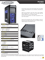
The ultimate evolution of high performance Mini-ITX
For years, SilverStone Sugo series has been the benchmark and the standard for high-performance
Mini-ITX chassis. The SG08-LITE was designed to retain all the signature features from the award-winning
SG08 such as the compact 14.8-liter design that can accommodate graphic card up to 12.2” and the premium
10mm aluminum front panel where SilverStone engineers have further updated the slim optical slot into
slot-loading variety for cleaner styling. Its specially designed fan bracket offers the users flexible cooling
options for 180mm fan or 120mm/140mm fan with water-cooling radiator. To keep dust out, all intake vents
are equipped with removable filters for easy-cleaning. In contrast with its relatively small size, the SG08-LITE
supports standard ATX PSU for greater selections and when used with SilverStone’s Strider Gold S series,
the smallest full modular power supplies with 80 PLUS Gold in the world, or our carefully engineered
SFX PSUs, the SG08-LITE can help you create an incredible Mini-ITX system.
SST-SG08B-LITE (black)
FRONT BACK
2
Extruded aluminum front panel, steel body USB 3.0 x 2 / audio x 1 / MIC x 1
Support standard ATX PSU up
to 160mm in length
Support expansion cards up to
12.2” long, width 4.84”*
222 mm (W) x 190 mm (H) x 351 mm
(D), 14.8 liters
Slim slot-loading optical x 1
3.5" x 1 , 2.5” x 2
120mm/140mm/180mm fan slot
Oversized vents
* To support graphics card longer than 7.25”, a non-modular PSU with maximum 140mm length is required.
VGA exhaust divider
Mini-DTX, Mini-ITX
SG08-LITE

TOP COVER
FAN BRACKET
FAN FILTER
PICTURE ITEM
SCREW A M2 X 2
SCREW B M3 X 4 Secure 2.5" SSD/HDD
Secure optical drive
Secure motherboard
Secure 3.5" SSD/HDD
SCREW C 632 X 6
SCREW D 632 X 10
WIRE - MOUNT
INSTALLATION GUIDE
PURPOSE
ATX PSU (OPTION)
MINI - ITX (OPTION)
EXPANSION
SLOT X 2
PSU FILTER
POWER LED & HDD LED
POWER BUTTON
USB 3.0 + SPK + MIC
SLIM SLOT - LOADING
OPTICAL DRIVE (OPTION)
2.5”HDD X 2
3.5” HDD X 1
HDD CAGE
Disassemble chart

Unscrew screws holding the top
cover and then remove it by pulling
to the rear and away from
the chassis.
Unscrew screws holding the fan
bracket and then pull up and
away from the case.
請以螺絲起子將上蓋鎖固的螺絲卸下,
並向後拉起自機殼中取出
请以螺丝起子将上盖锁固的螺丝卸下,
并向后拉起自机壳中取出
상부커버를 고정하고 있는 나사를
제거한후, 뒤쪽으로 당겨 커버를
제거합니다.
팬 브라켓을 고정하고 있는 나사를
제거한 후, 위로 당겨 올려
케이스로부터 제거합니다.
上部カバーを固定しているネジを外し
てから後方に引き、ケースから取り外
します。
ファンブラケットを固定しているネジ
をはずし、引き上げて、ケースから取
り外します。
将锁固风扇架的螺丝卸下,并向前往上
拉起自机壳中取出
將鎖固風扇架的螺絲卸下,並向前往上
拉起自機殼中取出
Lösen Sie die Schrauben an der
oberen Abdeckung; entfernen
Sie die Abdeckung, indem Sie
diese nach hinten vom Gehäuse
wegziehen
Quite los tornillos que sujetan la
cubierta superior y luego quítela
empujando hacia la parte trasera y
fuera del chasis
Svitare le viti che tengono il cover
superiore e quindi rimoverlo
tirandolo verso la parte posteriore.
Svitare le viti che tengono il
supporto della ventola, quindi
rimuoverlo dal case.
Выкрутите крепежные винты
кронштейна вентилятора, а затем
потяните его вверх и всторону от
корпуса.
Dévisser les vis arrière
maintenant le capot supérieur et
tirer le capot supérieur vers
l’arrière.
Dévisser les vis maintenant le
support de ventilateur, puis tirez
vers le haut.
Quite los tornillos que sujetan el
bracket del ventilador y luego tire
de él hacia arriba y fuera de la
carcasa.
Lösen Sie die Schrauben der
Kühlerhalterung; ziehen Sie die
Halterung vom Gehäuse ab
Выкрутите крепежные винты
верхней крышки, а затем снимите
ее, потянувназад и в сторону от
корпуса.
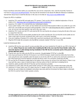
Installation Guide

Unscrew screws holding the
optical drive bracket to
remove it.
Unscrew screws holding the hard drive
bracket to remove it.
Loosen the screw on the PSU cage
to remove it.
Secure the PSU onto the PSU cage.
Secure the PSU cage onto the chassis
with screws. Connect the power cord.
將鎖固光碟架的螺絲卸下,並移除光碟架
光学ドライブブラケットを固定してい
るネジを外して取り外します。
광드라이브 브라켓을 고정하고 있는
나사를 풀어 브라켓을 제거합니다
将锁固光盘架的螺丝卸下,并移除光盘架
① 將鎖固硬碟架的螺絲卸下,並移除硬碟架
② 將鎖固電源架的螺絲卸下,並移除電源架
③ 將電源安裝上電源架
④ 裝回機殼,接上電源接線
① ハードドライブブラケットを固定しているネジを外
して、取り外します。
② PSUケージのネジを緩めて取り外します。
③ PSUケージへPSUを固定します。
④ ケースにPSUケージをネジで固定します。 電源コー
ドを接続します。
① 하드드라이브 브라켓을 고정하고 있는 나사를 풀어
브라켓을 제거합니다.
② PSU 케이스의 나사를 풀어 케이스를 분리합니다.
③ PSU를 PSU 케이스에 고정합니다.
④ 나사를 사용하여 PSU 케이스를 섀시에
고정합니다. 전원 코드를 연결합니다.
① 将锁固硬盘架的螺丝卸下,并移除硬盘架
② 将锁固电源架的螺丝卸下,并移除电源架
③ 将电源安装上电源架
④ 装回机壳,接上电源接线
Lösen Sie die Schrauben der
Festplattenhalterung; entfernen Sie sie.
Lösen Sie zum Abnehmen die
Schraube an der Netzteilhalterung.
Fixieren Sie das Netzteil an der
Netzteilhalterung.
Fixieren Sie die Netzteilhalterung mit
Schrauben am Gehäuse.Schließen Sie
das Stromkabel an.
Dévisser les vis maintenant le support
de disque dur puis le retirer.
Desserrez la vis sur la cage PSU
pour la retirer.
Fixez le PSU sur la cage PSU
Fixez la cage PSU sur la masse avec
les vis. Branchez le cordon
d’alimentation.
Per rimuovere il supporto deglihard
disk svitare le viti che lo assicurano
alla struttura.
Allentare la vite sulla gabbia PSU
per rimuoverlo.
Fissare il PSU sulla gabbia PSU.
Fissare la gabbia PSU al telaio con
le viti. Collegare il cavo di
alimentazione.
Выкрутите крепежные винты
кронштейна жесткого диска, чтобы
извлечь его.
Отвинтите винт кронштейна блока
питания и извлеките его.
Закрепите блок питания в
кронштейне.
Закрепите кронштейн блока питания
на корпусе
с помощью винтов.
Подключите шнур питания
Quite los tornillos que sujetan el
bracket del disco duro para
sacarlo.
Afloje el tornillo de la carcasa
de la FA para retirarla.
Fije la FA a la carcasa de la FA.
Fije la carcasa de la FA al
chasis con tornillos. Conecte el
cable de potencia.
Entfernen Sie die Abdeckung des
optischen Laufwerks, indem Sie
die in der Abbildung gezeigten
Schrauben lösen.
Выкрутите крепежные винты
кронштейна привода оптических
дисков, чтобы извлечь его.
Dévisser les vis maintenant le
support de lecteur optique puis le
retirer.
Quite los tornillos que sujetan el
bracket del dispositivo óptico para
retirarlo.
Svitare le viti che tengono il supporto
del drive ottico per rimuoverlo.
Installation Guide

Insert the I/O shield included
with your motherboard and then
install the motherboard into
the case.
Connect ATX 24pin,
EPS 8pin/ATX 4pin connectors,
front panel connectors, and
front I/O connectors to your
motherboard.
安裝主機板的I/O彈片,安裝主機板
安装主板的I/O弹片,安装主板
Setzen Sie das mit Ihrem
Motherboard gelieferte I/O-Blech in
die Aussparungen an der Rückseite
des Gehäuses ein, installieren Sie
anschließend das
Установите экранированную
панель ввода/вывода системной
платы, а затем установите саму
системную плату.
Подключите 24-контактные
ATX-разъемы, 8-контактные
EPS-разъемы/4-контактные
ATX-разъемы, разъемы передней
панели, а также передние разъемы
ввода/вывода к системной плате.
Insérez la plaque d'E/S inclus avec
votre carte mère, puis installez la
carte mère dans le boîtier.
Inserte el protector de E/S incluido
en su placa base, luego instale la
placa base en la carcasa.
Installare l’I/O shield della scheda
madre e quindi la scheda madre
stessa.
Verbinden Sie die 24-poligen
ATX-, 8-poligen EPS- / 4-poligen
ATX-, die Frontblenden- und die
E/A-Frontanschlüsse
mit Ihrem Motherboard.
Connecter l’ATX 24 broches, le EPS
8pin/ATX 4pin et les prises
additionnelles à la carte mère.
Enchufe los conectores ATX de 24
pines, EPS 8 pines/ATX 4 pines, del
panel frontal y los conectores
frontales de E/S a la placa base.
Connettere alla scheda madre il
cavo ATX 24pin, ove necessario il
cavo EPS ATX 4pin/8pin, le
connessioni del pannello frontale e
quelle I/O.
此時你可以準備安插ATX24pin
EPS8in/ATX 4pin,機殼附帶的Front
I/O與Front panel controller
ATX 24ピン、EPS 8ピン/ATX 4ピンコネ
クタ、フロントパネルコネクタ、および
フロントI/Oコネクタをマザーボードに
接続します。
お持ちのマザーボードに付属のI/Oシール
ドを挿入してから、ケースの中にマザーボ
ードを取り付けます。
메인보드 후면 I/O 커버를 설치한 후
메인보드를 설치합니다.
ATX 24핀, EPS 8핀,/ATX 4핀 커넥터,
전면패널 커넥터와 전면 I/O 커넥터를
메인보드에 연결합니다.
此时你可以准备安插ATX24pin
EPS8in/ATX 4pin,机壳附带的Front
I/O与Front panel controller
Installation Guide

We recommend at this point to start thinking about routing the cables cleanly by fastening ATX 24pin and EPS 8pin/ATX 4pin cables on
a bridge next to the power supply bracket. You may need to store excess cables in the area located on the left side of the hard drive cage.
我們建議ATX 24Pin EPS8in/ATX 4pin電源線可以綁在PSU固定架旁的理線凸橋上,多餘的線材部份可以安置在硬碟架左邊的保留空間
この時点で、電源ブラケット横のブリッジ上にATX 24ピンとEPS 8ピン/ATX 4ピンケーブルを固定することで、ケーブル取り回しを
すっきりさせることを考慮するようお勧めします。
이지점에서 ATX 24핀 및 EPS 8핀/ATX 4핀 등 케이블을 정리해 파워 서플라이 옆에 있는 정리 브릿지에 고정시킬 것을 권장합니다.
我们建议ATX 24Pin EPS8in/ATX 4pin电源线可以绑在PSU固定架旁的理线凸桥上,多余的线材部份可以安置在硬盘架左边的保留空间
Wir empfehlen, an dieser Stelle eine saubere Kabelführung zu beachten, indem Sie die 24-poligen ATX- und 8-poligen
EPS-/4-poligen ATX-Kabel an einer Brücke neben der Netzteilhalterung befestigen.
Vi raccomandiamo, a questo punto, di iniziare a pensare ad una corretta sistemazione dei cavi. Unite quindi i due cavi di
alimentazione ed assicurateli per mezzo di una fascetta ad un “ponte” posto nei pressi del supporto dell’alimentatore.
Le recomendamos que en este momento empiece a pensar sobre enrutar los cables de un modo correcto enganchando los
cables ATX de 24 pines y EPS 8 pines/ATX 4 pines en un puente cerca del bracket de la fuente de alimentación.
Nous recommandons à ce point du montage de commencer à penser à l'agencement des câbles en attachant l'ATX 24 broches
et le 4 pin EPS 8pin/ATX sur le côté l'alimentation.
В данный момент рекомендуется подумать об аккуратной прокладке кабелей, для этого необходимо закрепить 24-контактные
ATX-кабели и 8-контактные EPS-кабели/4-контактные ATX-кабели на перемычке рядом с кронштейном блока питания.
Installation Guide

We recommend to route the USB and audio front I/O cables around the front of hard drive cage, there should be sufficient
bridges for fastening the cables.
Wir empfehlen die Führung der USB- und E/A-Audiofrontkabel um die Vorderseite des Festplattenkäfigs; es sollten genügend
Brücken zur Befestigung der Kabel vorhanden sein
La longueur de câble superflu peutêtre dissimulée sur le côté droit de la cage disque dur.
USB與AUDIO我建議硬碟架的前方繞過,前板上應當有足夠的凸橋安置
USBおよびフロントオーディオI/Oケーブルは、ハードドライブケージの前面周囲で取り回します。そこにはケーブルを固定する
ための十分な空間があるはずです。
USB와 전면 오디오 및 I/O 케이블을 하드 드라이브의 케이지 전면으로 돌려주어 정리를 할 것을 권합니다.
USB与AUDIO我建议硬盘架的前方绕过,前板上应当有足够的凸桥安置
Le recomendamos que enrute los cables USB y el cable frontal de E/S de audio alrededor de la parte frontal de la carcasa del
disco duro, donde hay suficientes bridas como para sujetar los cables.
Vi raccomandiamo di sistemare i cavi del pannello frontale I/O USB ed audio nei pressi della parte frontale della gabbia degli hard
disk, dove sono presenti sufficienti ponti per l’ancoraggio dei cavi stessi.
Рекомендуется прокладывать USB-кабели и аудиокабели к передним разъемам ввода/вывода вокруг верхней части
корзины для жестких дисков, там должно быть достаточно перемычек для крепления кабелей.
Installation Guide

Excess front panel connector
cables can be fastened on
the bottom panel of the case.
Install and secure 3.5” and
2.5” hard drives to the hard drive
cage with screws. The SG08-LITE’s
drive cage is compatible with
2.5” hard drives with 9.5mm
thickness or less.
Front Panel controller的多余线材
可以安置绑在底板
余ったフロントパネルコネクタケー
ブルはケースの底のパネルに固定で
きます。
불필요하거나 남는 패널커넥터와
케이블은 케이스 하부 패널에
고정하면 됩니다.
3.5” 및 2.5” 하드디스크를 하드
드라이브 케이지에 나사로 고정하여
설치합니다. SG08-LITE의 드라이브
케이지는 9.5mm 두께의 2.5” 하드
드라이브 와 호환됩니다.
3.5インチと2.5インチのハードドライブを
ハードドライブケージに取り付け、ネジで
固定します。 SG08-LITEのドライブケージ
は厚さ9.5mm以内の2.5インチのハードドラ
イブと互換性があります。
Front Panel controller的多余线材
可以安置绑在底板
Die restlichen Frontblenden-
Anschlusskabel können an der
unteren Blende des Gehäuses
befestigt werden.
L’excès de câble des prises
additionnelles peut-être dissimulé
dans le bas du boitier.
Installer et fixer les disques durs/SSD dans
les cages à l’aide de vis. Les emplacements
2.5 pouces sont compatibles avec les unités
de 9.5mm au maximum.
El exceso de cables conectores del
panel frontal se puede enganchar en
el panel inferior de la carcasa.
Instale y fije los discos duros de 3,5” y 2,5” a
la carcasa para discos duros usando tornillos.
La carcasa de la SG08-LITE es compatible
con discos duros de 2,5” con un grosor de
9,5mm o menos.
I cavi in eccesso possono essere
assicurati al fondo del case.
Installare ed assicurare gli hard disk da 3,5” e
da 2,5” alla gabbia con le apposite viti. La
gabbia di SG08-LITE è compatibile con hard
disk da 2,5” con uno spessore massimo di
9.5mm.
Излишки кабелей к разъемам
передней панели можно закрепить
на нижней панели корзины.
Installieren und befestigen Sie die 3,5- und
2,5-Zoll-Festplatten mit Schrauben am
Festplattenkäfig. Der Festplattenkäfig des
SG08-LITE ist mit 2,5-Zoll-Festplatten mit
einer Dicke von bis zu 9,5 mm kompatibel.
Установите 3,5-дюймовые и
2,5-дюймовые жесткие диски в корзину
и закрепите винтами. Корзина для
жестких дисков SG08-LITE совместима с
2,5-дюймовыми
жесткими дисками
толщиной 9,5 мм или менее.
把3.5"硬碟與2.5"硬碟安裝上硬碟架
,並鎖上螺絲。SG08-LITE的2.5"硬碟
僅支援9.5mm標準厚度
把3.5"硬盘与2.5"硬盘安装上硬盘架
,并锁上螺丝。SG08-LITE的2.5"硬盘
仅支持9.5mm标准厚度
Installation Guide

We recommend connecting all fan or SATA cables to the motherboard now as installation of graphics or expansion card may
prevent installation of these cables.
我建議您在安裝顯示卡之前先確定系統風扇的電源接頭與所有需要用的SATA接頭是否已經安裝好,某些主機板配置會導致安
裝好顯示卡之後風扇接線難以接上
グラフィックまたは拡張カードの装着により、ケーブルがインストールできなくなる可能性を考え、現在すべてのファンまた
はSATAのケーブルをマザーボードと接続するようにお勧めします。
그래픽카드나 다른 확장카드의 설치로 케이블 설치가 용이하지 않을 수 있어 현 상태에서 팬이나 SATA케이블을 메인보드에
모두 연결할 것을 권합니다.
我建议您在安装显示适配器之前先确定系统风扇的电源接头与所有需要用的SATA接头是否已经安装好,某些主板配置会导致安装
好显示适配器之后风扇接线难以接上
Wir empfehlen, nun alle Kühler- oder SATA-Kabel am Motherboard anzuschließen, da die Installation der Grafik- oder Erweiterungs-
karte die Verbindung dieser Kabel erschweren oder verhindern kann.
Le recomendamos que conecte ahora todos los cables SATA o de los ventiladores a la placa base, ya que la instalación de
una tarjeta gráfica o de expansión podría impedir la conexión de estos cables.
Nous recommandons de brancher tous les câbles SATA et FAN avant d’installer les cartes filles ou cartes graphiques.
Vi raccomandiamo di connettere alla scheda madre tutte le alimentazioni delle ventole o i cavi SATA a questo punto
dell’installazione. Il successivo montaggio di schede di espansione, o della scheda video potrebbe impedirne collegamento.
Теперь рекомендуется подключить все кабели вентиляторов и SATA-кабели к системной плате, так как установка
графической карты или платы расширения может помешать установке этих кабелей.
Installation Guide

Remove expansion slot screws to remove expansion slot covers.
請將鎖固擴充槽檔片的螺絲卸下,再將擴充槽檔片卸下
拡張スロットのネジを外して拡張スロットカバーを取り外します。
请将锁固扩展槽档片的螺丝卸下,再将扩展槽档片卸下
Lösen Sie zum Entfernen der Abdeckung die Schrauben des Erweiterungssteckplatzes.
Выверните винты слотов расширения, чтобы снять заглушки слотов.
Svitare le viti di serraggio dei cover degli slot di espansione per rimuovere i cover stessi.
Retirer les vis des slots d’extension pour retirer les caches.
Quite los tornillos de las ranuras de expansión para retirar las cubiertas de las ranuras de
expansión.
확장슬롯 나사를 풀어 확장슬롯 커버를 제거합니다.
Installation Guide

Install graphics or expansion card
into the case then connect any
required power cables to the card.
Reinstall top expansion slot cover
back to the case and secure
with screws.
安裝您的顯示卡或擴充卡,並連接上電源線
ケースの中にグラフィックまたは拡張カ
ードをインストールしてから、カードに
必要とされている電源ケーブルをみな接
続します。
그래픽카드나 확장카드를 케이스에
설치하고 필요하다면 카드에 파워
케이블을 연결합니다.
상부 확장 슬롯 커버를 재설치한 후
나사로 고정시킵니다.
上部の拡張スロットカバーをケースに戻
し、ネジで固定します。
安裝您的顯示卡或擴充卡,並連接上電源線
將擴充槽檔片裝回機殼並以步驟14的螺
絲鎖固
将扩展槽档片装回机壳并以步骤14的螺
丝锁固
Installieren Sie die Grafik- oder
Erweiterungskarte im Gehäuse;
schließen Sie dann alle erforderlichen
Netzkabel an der Karte an.
Installer les cartes graphiques ou
cartes filles et relier les câbles
nécessaires.
Installare la scheda grafica o alter
schede di espansione e collegare
qualsiasi cavo richiesto alle schede
stesse
Instale la tarjeta gráfica o de
expansión en la carcasa y luego
conecte cualquier cable de potencia
necesario a dicha tarjeta.
Bringen Sie die Abdeckung des
oberen Erweiterungssteckplatzes
wieder am Gehäuse an und
befestigen diese mit Schrauben.
Установите заглушку верхнего слота
расширения обратно в корпус и
закрепите винтами.
Установите графическую карту или
плату расширения в корпус, а затем
подключите к плате все
необходимые кабели питания.
Vuelva a situar la cubierta de la ranura
de expansión en la carcasa y fíjela
usando tornillos.
Reinstallare il cover superiore degli
slot di espansione ed assicurarlo con
le viti.
Réinstaller le cache des slots
d’extension à l’arrière du boitier à
l’aide de vis.
Installation Guide

Install slim optical drive onto the
optical drive bracket and secure
with included screws.
將風扇架裝回機殼(使用18cm風扇須注意電源
插座是被風扇框所包夾住的)並以步驟2卸下
的螺絲鎖固
将风扇架装回机壳(使用18cm风扇须注意电源
插座是被风扇框所包夹住的)并以步骤2卸下
的螺丝锁固
將薄型光碟機裝入光碟機架並以內附螺絲
鎖固
将薄型光驱装入光驱架并以内附螺丝锁固
Installieren Sie ein schmales
optisches Laufwerk an der Halterung
des optischen Laufwerks; befestigen
Sie dieses mit den mitgelieferten
Schrauben.
Installer le lecteur optique dans son
emplacement, et fixer le à l’aide de
vis
Instale el dispositivo óptico delgado
en el bracket para dispositivos
ópticos y fíjelo con los tornillos
incluidos.
Instale de nuevo el bracket para el
ventilador en la carcasa y fíjelo con
tornillos. (cuando instale un ventilador de
180mm, asegúrese de que la estructura
del ventilador cubre el conector de
potencia desde dentro)
Installer le support du ventilateur dans le
boitier à l’aide de vis (quand un ventilateur
de 180mm est installé, assurez-vous que
le cadre du ventilateur couvre la fiche de
la source d'alimentation depuis l'intérieur).
Installare il drive ottico slim sul
supporto e serrarlo con le viti.
슬림 광드라이브를 광드라이브
브라켓에 설치한후 나사로
고정합니다.
光学ドライブブラケットにスリム光
学ドライブをインストールし、付属
のネジによって固定します。
ケースの中にファンブラケットを戻し、ネ
ジ(180mmファン装着の際は、ファンフレー
ムが内側から電源のプラグを覆っているこ
とを確認してください。)
팬브라켓을 케이스에 재설치하고 나사로
고정합니다. (180mm 팬을 설치할 경우
팬의 프레임이 안쪽에서 전원 공급장치
플러그를 가리는지 확인하십시오.).
IУстановите тонкий привод
оптических дисков на
специальный кронштейн и
закрепите прилагающимися
винтами.
Installieren Sie die Kühlerhalterung
wieder im Gehäuse und befestigen sie
mit Schrauben. (wenn ein 180-mm-
Lüfter installiert ist, muss der Rahmen
des Lüfters den Netzteilstecker von
innen verdecken).
Install the fan bracket back into the case
and secure with screws (when an 180mm
fan is installed, make sure the frame of
fan is covering the power supply plug from
inside).
Reinstallare il supporto della ventola nel
case e serrarlo con le viti. (Quando è
installata una ventola da 180 mm,
assicurarsi che il telaio della ventola copra
la spina d’alimentazione dall'interno.)
Установите кронштейн вентилятора
обратно в корпус и закрепите винтами.
(при установке 180-мм вентилятора
его рамка должна закрывать разъем
питания
изнутри).
Installation Guide

Place the top cover back onto the case and secure with screws.
將上蓋裝回機殼並以步驟1卸下的螺絲鎖固
ケースに上部カバーを戻し、ネジで固定します。
将上盖装回机壳并以步骤1卸下的螺丝锁固
Platzieren Sie die obere Abdeckung wieder am Gehäuse und befestigen diese mit Schrauben.
Vuelva a poner la cubierta superior en la carcasa y fíjela con tornillos.
Riposizionare il cover superiore sul case ed assicurarlo alla struttura con le viti.
Установите верхнюю крышку обратно на корпус и закрепите винтами.
상부커버를 케이스에 재 설치한 후 나사로 고정시킵니다.
Remettre en place le capot supérieur du boitier et le fixer à l’aide de vis.
Installation Guide

(1) Front panel connector installation no polarity, so they can be connected in any orientation
Power switch and reset switch installation guide:
Please refer to the motherboard manuals for the motherboard’s “Front Panel Connector” or “System Panel Connector” pin definitio
Power switch and reset switch have no polarity, so they can be connected in any orientation.
Bitte suchen Sie in der Motherboard-Dokumentation nach der Pinbelegung der Anschlüsse des Frontbedienfeldes („Front Panel Conne
oder „ System Panel Connectors“). Ein-/Austaste und Rücksetztaste benötigen keine bestimmte Polarität, können daher beliebig (o
und - zu achten) angeschlossen werden.
Veuillez-vous référer au manuel de votre carte mère pour la description des broches "des connecteurs du panneau frontal" et des
"des connecteurs du panneau système". Les interrupteurs d'allumage et de réinitialisation ne possède pas de polarité, donc ils peuvent être
branché dans les deux sens.
Por favor, consulte en los manuales de la placa base la configuración de pines del “Conector de panel frontal” ó “Conector de panel de sistema”
de su placa base. Los interruptores de encendido y reseteo no tienen polaridad, luego se pueden conectar con cualquier orientac
Fare riferimento al manuale della scheda madre nella sezione “Connettori del pannello frontale” o “Connettori del pannello di sistema”. Power
switch e reset switch non hanno polarità, posso essere pertanto connessi con qualsiasi orientamento.
Описание контактов разъемов приведены в разделах “Разъемы передней панели” или “Разъемы системной панели” руководства
пользователя материнской платы. Выключатель питания и кнопка перезагрузки не имеют полярности, поэтому их можно подключать
в любой ориентации.
請參考主機說明書的Front Panel Connectors安裝Pin Define,將Connector插上;Power Switch 與Reset Switch並無正負極性之分,
反插正插都不影響功能性。
请参考主机说明书的Front Panel Connectors安装Pin Define,将Connector插上;Power Switch 与Reset Switch并无正负极性之分,
反插正插都不影响功能性。
메인보드 매뉴얼의 전면패널 커넥터 혹은 시스템패널 커넥터 핀을 참조하기 바랍니다. 파워 스위치와 리셋 스위치는 극성이 없어 어떤
방향으로 설치해도 무방합니다.
マザーボードの「フロントパネルコネクタ」または「システムパネルコネクタ」のピン配列についてはマザーボードマニュアルを参照してください。
電源スイッチとリセットスイッチに極性はないので、いずれの方向でも接続できま。
Connector definition

Please refer to the motherboard manuals for the motherboard’s “Front Panel Connector ” or “System Panel Connector” pin definition.; the white/black
wires are negative while other colors are positive wires. The Power LED wires are separate pins for compatibility with different motherboard pin
definition so please make sure they are connected in the right polarity by referring to your motherboard manual.
Bitte suchen Sie in der Motherboard-Dokumentation nach der Pinbelegung der Anschlüsse des Frontbedienfeldes („Front Panel Connectors“ oder „
System Panel Connectors“). Die weißen/ schwarz Adern sind negativ (-), die farbigen Adern positiv (+).Die Kabel für die Betriebsanzeige-LED sind
zur Kompatibilität mit unterschiedlichsten Motherboards einzeln, nicht als kompletter Stecker ausgeführt. Achten Sie hier bitte auf die richtige
Polarität, lesen Sie in der Dokumentation Ihres Motherboards nach.
Veuillez-vous référer au manuel de votre carte mère pour la description des broches "des connecteurs du panneau frontal" et des broches "des connecteurs du panneau
système". Les câbles colorés en blanc/noir sont négatifs alors que ceux d'une autre couleur sont positifs. Les câbles de la LED Power sont séparés afin d'être compatible
avec différentes cartes mères, donc vérifiez bien qu'ils sont branchés avec la bonne polarité en vous référant au manuel de votre carte mère
Por favor, consulte en los manuales de la placa base la configuración de pines del “Conector de panel frontal” ó “Conector de panel de sistema” de
su placa base. Los cables de color blanco/negro son negativos mientras que los de color son positivos. Los cables LED de potencia tienen pines
separados para compatibilidad con diferentes definiciones de pines de la placa base luego por favor, asegúrese de que están conectados en la
polaridad correcta consultando el manual de su placa base.
Fare riferimento al manuale della scheda madre nella sezione “Connettori del pannello frontale” o “Connettori del pannello di sistema”. I cavi di
colore bianco/nero sono il polo negativo, mentre quelli di colore diverso il positivo.
Описание контактов разъемов приведены в разделах “Разъемы передней панели” или “Разъемы системной панели” руководства
пользователя материнской платы. Белые/черный провода - отрицательной полярности, цветные провода - положительной полярности.
Провода светодиодного индикатора питания имеют отдельные контакты для совместимости с различными типами контактов материнских
плат, поэтому обратитесь к руководству пользователя материнской платы и убедитесь, что полярность соблюдена.
請參考主機說明書的Front Panel Connectors安裝Pin Define,將Connector插上; 白/黑色線的部分為負極,彩色線的部分是正極。
Power LED為了適應各主機板的不同, 特別設計為散Pin樣式,請安心使用。
请参考说明书的Front Panel Connectors安装Pin Define,将Connector插上;白/黑色线的部份为负极,彩色线的部份为正极。
Power LED为了适应主机板的不同, 特别设计为散Pin样式,请安心使用。
메인보드 매뉴얼의 전면패널 커넥터 혹은 시스템패널 커넥터 핀을 참조하기 바랍니다. 하얀/검은선의 경우 음극이며, 다른 색의 경우
양극입니다. 파워 LED 선은 분리되어 다양한 메인보드에서 동작할 수 있도록 되어 있습니다. 그러므로 메인보드 매뉴얼을 참조하여 올바를
극성을 주의해 선택하시기 바랍니다.
マザーボードの「フロントパネルコネクタ」または「システムパネルコネクタ」ピン配列についてはマザーボードマニュアルを参照してください。
白/黑色のリード線はマイナスで、色の着いたリード線がプラスです。電源LEDリード線は種々のマザーボードピン定義と互換性を持たせるため分離されたピ
ンとなっているので、ご使用のマザーボードマニュアルを参照して、適切な極性に接続されるようお確かめください。
LED indicators installation guide
Connector definition

Below are the front I/O connectors pin definition, please also check your motherboard manual to cross reference with motherboard’s
front I/O pin headers. SilverStone’s I/O connectors are in block type to simplify installation.
Nachstehend finden Sie die Pinbelegung der vorderen E/A-Anschlüsse; bitte gleichen Sie zudem das Handbuch Ihres Motherboards mit
den vorderen E/A-Pinzuweisungen ab. SilverStones E/A-Anschlüsse befinden sich zur Vereinfachung der Installation in Blockart.
Au dessous de la description des broches des ports d'E/S, veuillez aussi vérifier sur le manuel de votre carte mère de manière croisée
que les broches sont correctement placées. Les connecteurs d'E/S de SilverStone sont en bloc pour en simplifier leur installation.
A continuación tiene la definición de pines de los conectores frontales de E/S, también debe consultar el manual de su placa base para c
omprobar la referencia de los pines para E/S frontales. Los conectores de E/S de SilverStone son de bloque para simplificar la instalación.
Di seguito lo schema delle connessioni I/O frontali, confrontare lo schema con quanto riportato sul manuale della scheda madre per
effettuare una controllo incrociato. I connettori I/O Silverstone, per semplificare l’installazione, sono del tipo “a blocco”.
Ниже приведено описание контактов передних разъемов ввода/вывода. Обратитесь также к руководству пользователя материнской
платы за описанием передних разъемов ввода/вывода типа "пин-хедер". Разъемы ввода/вывода "SilverStone" - блочного типа, что
облегчает сборку.
下表為Front I/O Connectors的Pin Define,請參閱主機板說明書的各Front I/O Connectors Pin Define一一核對。
Front I/O Connectors完全採用集合Pin方式以簡化安裝。
下表为Front I/O Connectors的Pin Define,请参阅主机板说明书的各Front I/O Connectors Pin Define一一核对。
Front I/O Connectors完全采用集合Pin方式以简化安装。
아래는 전면 I/O 커넥터의 핀 설정이며, 메인보드 매뉴얼을 참조해 메인보드의 전면 I/O 핀 헤더와 맞추어 설치합니다.
Silverstone의 I/O 커낵터는 블록 타이브로 구성되어 설치를 간편화 했습니다.
以下はフロントI/Oコネクタピン配列ですが、お持ちのマザーボードのフロントI/Oピンヘッダは、マザーボードマニュアルをご参照ください。
シルバーストーンのI/Oコネクタは、インストールの容易なブロックタイプになっています。
Front I/O connector guide

The SG08-LITE can accommodate all standard size components and even some
that are out of spec, please refer to the following guidelines for component selection
and future upgrade considerations.
The SG08-LITE supports power supply with depth of up to 160mm. To support graphics card longer than 7.25”, a non-modular PSU
with maximum 140mm depth is required. The cables are required to be on the right side of the PSU
Das SG08-LITE unterstützt Netzteile mit einer Tiefe von bis zu 160 mm.Zur Unterstützung langer Grafikkarten (über 7,25 Zoll/18,415 cm)
darf das ATX-Netzteil nur 140 mm messen und nicht modular sein. Die Kabel müssen auf der rechten Seite des Netzteils verlaufen.
CPU cooler height limitation 147mm
Power supply depth limitation 140mm
(1) CPU cooler height limitation
(2) PSU limitation
Depth limitation
Component size limitations

The PSU above 800w is not recommended because of the adapter cable
Netzteile über 800 W sollten aufgrund des Adapterkabels nicht verwendet werden
Les blocs d'alimentations supérieurs à 800w ne sont pas recommandés, à cause du câble adaptateur
Una FA por encima de 800W no se recomienda por el cable adaptador
PSU di potenza superiore a 800W non sono raccomandate a causa del cavo adattatore
Блок питания мощностью свыше 800 Вт устанавливать не рекомендуется из-за кабеля адаптера.
어댑터 케이블 때문에 800w 이상의 PSU는 권장하지 않습니다.
800wを超えるPSUはアダプタケーブルの関係上お勧めできません。
因為轉接線的原因,不建議安裝超過800W的電源
因为转接线的原因,不建议安装超过800W的电源
SFX Series (ATX adapter included)
Strider Gold Series
Strider Plus Series (under 800w)
Nightjar Series
위의 그림은 PSU 브래킷의 레이아웃입니다. 모든 구성부품이나 커넥터는 이 영역 안으로 들어와서는 안 됩니다(예: 스위치 또는 LED).
上記がPSUブラケットのレイアウトです。いずれのコンポ ネントやコネクタ(例:スイッチまたはLED)もこのエリア
には入らないようにしてください。
上圖為電源架的機構圖,在此範圍內不允許任何接頭或是元件(例如開關/LED)
上图为电源架的机构图,在此范围内不允许任何接头或是组件(例如开关/LED)
Wattage limitation
Strider Essential Series
Recommended SilverStone’s PSU
(support the installation of long graphic card)
Compatible SilverStone’s PSU
Component size limitations

(4) Optical drive limitation
The SG08-LITE only supports 12.7mm slim “slot-loading” optical drives.
Below is an example of 12.7mm optical drive
Das SG08-LITE unterstützt nur schmale optische Laufwerke („Slot-In“).
Nachstehend finden Sie Beispiele zu optische 12,7 mm-Laufwerke.
Le SG08-LITE est compatible seulement avec le lecteur optique slim sans tiroir de 12,7mm (mange-disque aka “slot-loading”).
Un exemple de lecteur optique de 12,7 mm est présenté.
La SG08-LITE sólo acepta dispositivos ópticos delgados de carga mediante ranura.
Más abajo hay ejemplo de dispositivo óptico de 12,7mm.
SG08-LITE은 슬립 슬롯 방식의 광드라이브만 지원합니다.
아래의 예는 12.7 mm광학 드라이브의 예입니다.
SG08-Lite只能使用12.7mm吸入式薄型光碟機
以下是12.7mm的光碟機範例供您做參考
SG08-Lite只能使用12.7mm吸入式薄型光驱
以下是12.7mm的光驱范例供您做参考
SG08-LITEはスリムタイプ「スロットローディング」光学ドライブのみをサポートします。
下図は、12.7mmの光学ドライブの例です。
Корпус SG08-LITE допускает только установку тонких оптических приводов со «щелевой загрузкой».
Ниже приведены примеры оптический привод толщиной 12,7 мм.
SG08-LITE supporta soltanto drive ottici slim “slot-loading” .da 12,7mm.
Di seguito vengono illustrati esempi di unità ottica da 12,7 mm.
Component size limitations

Using SilverStone’s NT06-PRO without CPU fan is possible on CPU with TDP rated up to 95W. With a 120mm fan installed on the NT06-P,
the use of a CPU with TDP rating of up to 130W is possible. We recommend using SATA connector with 90 degree angle for the 3.5” hard drive
in order to use larger CPU cooler such as SilverStone’s NT06-P or bigger.
Die Nutzung des NT06-PRO von SilverStone ohne CPU-Kühler ist bei CPUs mit einer TDP-Angabe von bis zu 95 W möglich. Wenn Sie im
NT06-PRO einen 120 mm-Kühler installieren, ist die Nutzung einer CPU mit einer TDP-Angabe von bis zu 140 W möglich. Wir empfehlen die
Nutzung eines SATA-Anschlusses mit einem 90-Graf-Winkel für 3,5-Zoll-Festplatten zur Nutzung eines großen CPU-Kühlers wie z. B. dem
NT06-PRO von SilverStone.
Utiliser le SilverStone NT06-PRO sans ventilateur est possible, sur un CPU dont le TDP n’excède pas 95 watts. Avec un ventilateur de
120mm installé sur le NT06-E, il est alors possible d’utiliser des CPU avec un TDP de 140 watts. Nous recommandons l’emploi de câble SATA
à 90° pour le disque dur 3.5 pouces afin d’utiliser un ventirad CPU comme le SilverStone NT06-PRO ou plus volumineux.
Es posible usar la NT06-PRO de Silverstone sin ventilador con micros que tengan TDP (Thermal Design Power, cantidad de calor que necesita
disipar un ordenador) de hasta 95V. Con un ventilador de 120mm instalado en la NT06-PRO, es posible usar un micro con un TDP de hasta 140V.
Le recomendamos que use un conector SATA con ángulo de 90 grados para el disco duro de 3,5”, y así poder usar un refrigerador para el micro
más grande, como el NT06-PRO de Silverstone o mayor.
Il dissipatore SilverStone NT06-PRO può essere utilizzato senza ventola con CPU che non abbiano un TDP superiore ai 95W. Con una ventola
da 120mm è possibile adottare CPU con TDP fino a 140W. Vi raccomandiamo di utilizzare cavi SATA con connettori a 90° per gli hard disk da
3,5” al fine di poter utilizzare dissipatore di calore di maggiori dimensioni come il SiverStone NT06-PRO o addirittura più grandi.
SilverStone NT06-PRO можно использовать без вентилятора центрального процессора в том случае, если расчетная тепловая мощность
процессора не превышает 95 Вт. При установке на NT06-PRO вентилятора размером 120 мм можно использовать центральный процессор
с расчетной тепловой мощностью до 140 Вт. Рекомендуется использовать
угловой SATA-разъем (90 градусов) для 3,5-дюймового
жесткого диска, чтобы можно было установить вентилятор центрального процессора большего размера, например, SilverStone NT06-PRO
или еще больше.
SilverStone의 NT06-PRO는 CPU팬 없이 TDP 기준 95W까지 지원할 수 있습니다. NT06-PRO에 120mm 팬을 추가로 장착할 경우 TDP 기준
140W까지 사용이 가능합니다. 3.5” 하드디스크 사용시 SilverStone의 NT06-PRO등 큰 CPU쿨러 사용을 위해 90도 SATA 커넥터를 사용할 것을
권합니다.
CPUファンなしでSilverstoneのNT06-PROを使うことは最大定格95WのTDPを有するCPU上で可能です。120mmファンをNT06-PROにインス
トールした状態では、最大定格140WのTDPを有するCPUの使用が可能です。SilverstoneのNT06-PROまたは、より大きなCPUクーラーを使う
には、3.5インチのハードドライブのために90度アングルSATAコネクタを使うようお勧めします。
使用NT06-PRO可以支援 TDP 95W的CPU,安裝系統風扇後可支援130W的CPU,須注意使用NT06或更大型散熱器時3.5”硬碟最好是使用
90度接頭的樣式以避免與Cooler干涉。
使用NT06-PRO可以支持 TDP 95W的CPU,安装系统风扇后可支持130W的CPU,须注意使用NT06或更大型散热器时3.5”硬盘最好是使用
90度接头的样式以避免与Cooler干涉。
Optimal Thermal Performance Layout
/