
OPERATING GUIDE
PLEASE READ THIS ENTIRE GUIDE BEFORE BEGINNING

Hereinafter Radio Systems Corporation, Radio Systems PetSafe Europe Ltd., Radio Systems Australia Pty Ltd. and any other affiliate or
Brand of Radio Systems Corporation may be referred to collectively as “We” or “Us”.
IMPORTANT SAFETY INFORMATION
Explanation Of Attention Words And Symbols Used In This Guide
This is the safety alert symbol. It is used to alert you to potential personal injury hazards. Obey all safety
messages that follow this symbol to avoid possible injury or death.
WARNING
WARNING indicates a hazardous situation which, if not avoided, could result in death or serious
injury.
CAUTION, used with the safety alert symbol, indicates a hazardous situation which, if not
avoided, could result in minor or moderate injury.
CAUTION, used without the safety alert symbol, indicates a hazardous situation which, if not
avoided, could result in harm to your dog.
NOTICE is used to address safe use practices not related to personal injury.
WARNING
• Don’t use this product if your dog is aggressive or prone to aggressive behavior. Aggressive dogs can cause severe injury and even
death to owners and others. If you’re unsure whether this product is appropriate for your dog, please consult your veterinarian or a
certified trainer.
• Underground cables can carry high voltage. Have all underground cables marked before you dig to bury the boundary wire. In most
areas, it’s a free service. Don’t install, connect, or remove your system during a lightning storm. If the storm is close enough for you
to hear thunder, it’s close enough to create hazardous surges.
• To avoid risk of severe injury, follow all safety instructions for your power tools, and wear safety goggles during use.
• Before you begin installing the Boundary Wire, turn the Fence Transmitter OFF.
• To avoid electric shock, use the containment Transmitter indoors in a dry location only.
• DON’T attempt to cut into or pry open the battery. Be sure to discard any used battery properly.
• Never incinerate, puncture, deform, short-circuit or charge with an inappropriate charger. Fire, explosion, property damage, or
bodily harm may occur if this warning is not followed.
• There is a risk of explosion if a battery is replaced by an incorrect type. Do not short circuit, mix old and new batteries, dispose of in
fire, or expose to water. When batteries are stored or disposed, they must be protected from shorting.
• The battery should be charged in areas with temperatures ranging from 32°F to 113°F / 0°C to 45°C. Recharging the battery outside of
this temperature range can cause the battery to overheat, explode, or catch fire.
• Wire on top of the ground may be a trip hazard. Be careful when placing wires and testing the system.
• This system is NOT a solid barrier. It’s designed to act as a deterrent to remind dogs to remain within the established boundary by
use of static stimulation. It’s important that you reinforce training with your dog on a regular basis. Since the tolerance level to static
stimulation varies from dog to dog, Radio Systems Corporation CANNOT guarantee that the system will, in all cases, keep a dog
within the established boundary. Not all dogs can be trained to avoid crossing the boundary! Therefore, if you have reason to believe
that your dog may pose a danger to others or harm himself if he is not kept from crossing the boundary, you should NOT rely solely
upon this system to confine your dog. Radio Systems Corporation shall NOT be liable for any property damage, economic loss, or any
consequential damages sustained as a result of any animal crossing the boundary.
• It’s vitally important that you and your dog remain safe during on-leash training. Your dog should be on a strong lead/leash, long
enough for him to attempt to chase an object, but short enough for him not to reach a road or other hazard. You must be physically
strong enough to restrain your dog if he tries to chase something.
• Proper fit of the collar is important. A collar worn for too long or made too tight on the dog’s neck may cause skin damage ranging
from redness to pressure ulcers. This condition is commonly known as bed sores.
• Avoid leaving the collar on a dog for more than 12 hours per day.
• When possible, reposition the collar on the dog’s neck every 1 - 2 hours.
• Regularly recheck the fit to prevent excessive pressure; follow the instructions in this manual.
• You may need to trim the hair in the area of the Contact Points. However, never shave the dog’s neck; this may lead to a rash or
infection.
• Never connect a lead/leash to a collar with Contact Points. It will cause excessive pressure on the Contact Points.
• When connecting a lead/leash to a separate collar, don’t allow it to put pressure on the Collar Receiver.
• Wash the dog’s neck area and the Contact Points of the collar weekly with a damp cloth.
• Examine the contact area daily for signs of a rash or a sore.
• If a rash or sore is found, discontinue using this product until the skin has healed.
• If the condition persists beyond 48 hours, see your veterinarian.
• For additional information on bed sores and pressure necrosis, please visit www.sportdog.com.
• Proper training of your dog is essential to successfully using the system. During the first 2 weeks of training, don’t use the system
without direct supervision of your dog.
• Always remove your dog’s Collar Receiver before performing any Transmitter testing or adjustments. This will prevent unintended
corrections.
• To prevent an unintended correction, after the boundary markers have been placed and you are beginning your containment
training, be sure to set the static stimulation level on the collar back to Level 1 (or tone/vibe), and only increase if necessary.
• The boundary width of the system must be tested whenever an adjustment is made to the Boundary Area to prevent unintended
corrections to your dog. Don’t use an outlet protected with a residual current device (RCD) or ground fault circuit interrupter (GFCI).
The system will function properly, but in rare cases, nearby lightning strikes may cause the RCD or GFCI to trip. Without system
power, your dog may escape. You’ll have to reset the RCD or GFCI to restore power to the system.
• This product is only for use with healthy dogs. If you’re not certain that your dog is in good health, we recommend that you take your
dog to a veterinarian before using this product.
• Avoid damaging the insulation of the loop wire; damage may cause areas of weak signal and lead to failure of the boundary.
• When mowing or trimming your grass, use care not to cut the Boundary Wire.
• To protect the containment Transmitter, disconnect the Boundary Wire and unplug the power adapter from the outlet when the
system will not be used for long periods of time or prior to thunderstorms. This will prevent power surges from damaging the
Transmitter.
• Modification or changes to this equipment not expressly approved by Radio Systems Corporation may void the user’s authority to
operate the equipment.

4 1-800-732-0144
WWW.SPORTDOG.COM 5
Thank you for choosing SportDOG
™
Brand. Used properly, this product will help you contain and train your dog efficiently and safely. To
ensure your satisfaction, please review this Operating Guide thoroughly. If you have questions regarding this product’s operation, please
see the Frequently Asked Questions and Troubleshooting sections, contact our Customer Care Center, visit our website at
www.sportdog.com, or view our support videos at www.youtube.com/sportdogbrand.*
To get the most protection out of your 2 year warranty, please register your product within 30 days at www.sportdog.com. By
registering you’ll enjoy the product’s full warranty and, should you ever need to call the Customer Care Center, we’ll be able to help you
faster. Most importantly, your valuable information will never be given or sold to anyone. Complete warranty information is available
online at www.sportdog.com.
TABLE OF CONTENTS
COMPONENTS ................................................................................................................................................................................... 5
OTHER ITEMS YOU MAY NEED ............................................................................................................................................................ 5
HOW THE SYSTEM WORKS ................................................................................................................................................................. 6
KEY DEFINITIONS .............................................................................................................................................................................. 6
OPERATING GUIDE
PREPARE THE COLLAR RECEIVER ....................................................................................................................................................... 8
PREPARE THE REMOTE TRANSMITTER .............................................................................................................................................. 11
FIT THE COLLAR RECEIVER ...............................................................................................................................................................12
FIND THE BEST INTENSITY LEVEL FOR YOUR DOG (TRAINING) ...........................................................................................................12
CHANGING THE STATIC STIMULATION RANGES (TRAINING) ................................................................................................................13
GENERAL TRAINING TIPS .................................................................................................................................................................. 13
PROGRAM THE REMOTE TRANSMITTER ............................................................................................................................................14
MATCH THE COLLAR RECEIVER AND REMOTE TRANSMITTER .............................................................................................................15
PROGRAM THE SYSTEM FOR MULTI-DOG OPERATION ........................................................................................................................15
CHANGE ID CODES ............................................................................................................................................................................15
INSTALL THE FENCE TRANSMITTER ..................................................................................................................................................16
LAY OUT THE SYSTEM .......................................................................................................................................................................16
POSITION THE BOUNDARY WIRE .......................................................................................................................................................18
CONNECT THE WIRES TO THE FENCE TRANSMITTER ..........................................................................................................................19
SET THE BOUNDARY WIDTH AND TEST THE COLLAR RECEIVER ......................................................................................................... 20
INSTALL THE BOUNDARY WIRE .........................................................................................................................................................21
PLACE THE BOUNDARY FLAGS ......................................................................................................................................................... 22
TRAINING GUIDE – CONTAINMENT
DAY 1 - BOUNDARY FLAG AWARENESS .............................................................................................................................................. 23
DAYS 2 THRU 4 - CONTINUE BOUNDARY FLAG AWARENESS ............................................................................................................... 24
DAYS 5 THRU 8 - DISTRACTION PHASE ............................................................................................................................................. 24
DAYS 9 THRU 14 - UNLEASHED SUPERVISION ................................................................................................................................... 25
DAYS 15 THRU 30 - MONITORING YOUR DOG ..................................................................................................................................... 25
TAKING YOUR DOG OUT OF THE BOUNDARY AREA ............................................................................................................................ 25
ACCESSORIES .................................................................................................................................................................................. 26
FREQUENTLY ASKED QUESTIONS ..................................................................................................................................................... 27
TROUBLESHOOTING ........................................................................................................................................................................ 28
SHORT LOOP TEST ........................................................................................................................................................................... 29
TO LOCATE A BREAK IN THE BOUNDARY WIRE .................................................................................................................................. 29
TEST LIGHT ..................................................................................................................................................................................... 30
TERMS OF USE AND LIMITATION OF LIABILITY ................................................................................................................................. 30
BATTERY DISPOSAL ......................................................................................................................................................................... 30
COMPLIANCE ...................................................................................................................................................................................31
CUSTOMER CARE INTERNATIONAL ....................................................................................................................................................31
WARRANTY ..................................................................................................................................................................................... 32
MOUNTING TEMPLATE .................................................................................................................................................................... 34
LAYOUT GRID .................................................................................................................................................................................. 35
* videos available at www.youtube.com/sportdogbrand
COMPONENTS
OTHER ITEMS YOU MAY NEED
• Additional wire and flags (SDF-WF)
• Measuring tape
• Drill and mounting hardware
• Shovel or lawn edger
• Pliers
• Wire stripping pliers
• Scissors
• Additional gel-filled capsules and wirenuts
• Ground rod and clamp
• PVC pipe or water hose
• Circular saw with masonry blade for burying wire in hard surfaces
• Patching compound
• Staple gun
• Non-metallic collar and lead/leash

6 1-800-732-0144
WWW.SPORTDOG.COM 7
HOW THE SYSTEM WORKS
The SportDOG
™
Brand Contain + Train
™
system has been proven safe, comfortable, and effective for dogs over 10 pounds. In
Containment and Contain + Train modes, the system works by producing a radio signal from the Fence Transmitter through up to 8,600
feet of Boundary Wire. The Boundary Wire is buried or attached to a fixed object to enclose the dog’s Boundary Area. You temporarily
define the Boundary Area with Boundary Flags for a visual aid in training your dog. Your dog wears a Collar Receiver with Contact Points
that touch his neck and, once trained, is allowed to roam freely in the Boundary Area. When your dog reaches the Warning Zone, the
Collar Receiver gives a warning beep. If your dog continues into the Stimulation Zone, a safe stimulation will be delivered through the
Contact Points to get his attention until he returns to the Boundary Area.
In Training mode, consistent, correct use of this product allows you to reinforce commands from up to 500 yards. The Remote
Transmitter sends a signal, activating the Collar Receiver to deliver stimulation. With proper training, a dog will
learn to associate this signal with a command. Like all SportDOG products, this model features adjustable static
stimulation levels so you can tailor the stimulation level to your dog’s temperament, eliminating the risk of over-
correction.
IMPORTANT: WHEN TRAINING, THE CONTAIN + TRAIN SYSTEM HAS A RANGE OF UP TO 500 YARDS.
DEPENDING ON THE WAY YOU HOLD THE REMOTE TRANSMITTER, THE MAXIMUM RANGE MAY VARY. FOR
CONSISTENT RESULTS AT LONGER RANGES, HOLD THE REMOTE TRANSMITTER IN A VERTICAL POSITION
AWAY FROM YOUR BODY AND ABOVE YOUR HEAD. TERRAIN, WEATHER, VEGETATION,TRANSMISSION FROM
OTHER RADIO DEVICES, AND OTHER FACTORS WILL AFFECT THE MAXIMUM RANGE.
WARNING
Do not use this product if your dog is aggressive, or if your dog is prone to aggressive behavior. Aggressive dogs can
cause severe injury and even death to their owner and others. If you are unsure whether this product is appropriate for your dog, please
consult your veterinarian or a certified trainer.
KEY DEFINITIONS
FENCE TRANSMITTER: The power source that transmits the radio signal through the Boundary Wire.
BOUNDARY AREA: The area inside the Warning Zone where your dog can roam freely.
WARNING ZONE: The perimeter of the Boundary Area where your dog’s Collar Receiver begins to beep, warning him not to go into the
Stimulation Zone.
STIMULATION ZONE: The zone beyond the Warning Zone where your dog’s Collar Receiver will deliver a stimulation, signaling him to
return to the Boundary Area.
BOUNDARY WIDTH: The area covered by the Warning Zone and the Stimulation Zone.
STIMULATION MODE SWITCH: Used to select the type of stimulation delivered by the Collar Receiver.
RANGE SWITCH: The switch to adjust the Boundary Area according to the length of Boundary Wire used.
POWER JACK: The jack where the Power Adapter plugs into the Fence Transmitter. The Fence Transmitter is powered by a standard
electrical outlet.
RANGE ADJUSTER: The knob that adjusts
the width of the Warning and Stimulation
Zones.
Note: Adjusting the knob does not change
the level of static stimulation on the Collar
Receiver.
LOOP INDICATOR LIGHT: The light that
indicates that the Boundary Wire makes a
complete loop, enabling the signal to be
transmitted.
GROUND TERMINAL: The terminal where
the ground wire connects to the Fence
Transmitter.
BOUNDARY WIRE TERMINALS: The
terminals where the Boundary Wires
connect to the Fence Transmitter in order to
complete a continuous loop.
Boundary Area
Static Stimulation
Zone
Static Stimulation
Zone
Fence
Transmitter
Warning
Zone
Warning
Zone
Boundary
Width
PO
W
E
R
O
N
LOO
P
INDI
CA
TO
R
G
RO
U
ND
BO
U
NDA
R
Y
W
I
R
E
TE
R
M
INA
L
S
Power
Light
Loop
Indicator
Light
Boundary
Wire
Terminals
Ground
Terminal
Power
Jack
7K/10K Frequency Switch
On/Off
Switch
Range
Switch
Stimulation
Mode
Switch
Range
Adjuster
FENCE TRANSMITTER
HOW THE SYSTEM WORKS
KEY DEFINITIONS
REMOTE TRANSMITTER
REMOTE TRANSMITTER: Transmits the radio signal to the Collar Receiver. It
is DryTek
™
- waterproof and submersible to 25 feet.
INTENSITY DIAL: Provides multiple levels of static stimulation so you can
match the correction to your dog’s temperament.
TRANSMITTER INDICATOR LIGHT: Indicates that a button is pressed and
also serves as a low-battery indicator.
UPPER BUTTON: This button is factory set to deliver continuous static
stimulation.
LOWER BUTTON: This button is factory set to deliver momentary static
stimulation.
SIDE BUTTON: This button is factory set to deliver a tone without static
stimulation.
CHARGING JACK: For connecting the charger. Although the Remote
Transmitter is waterproof without it, keep the cover in place when not
charging to keep debris out of the opening.
MODE BUTTON: This button gives you the ability to change the mode of your
Remote Transmitter (see page 14).
COLLAR RECEIVER
RECEIVER
INDICATOR
LIGHT
OLED
DISPLAY
POWER BUTTON
PLUS/MINUS
BUTTONS
CONTACT POINTS
COLLAR RECEIVER: Receives the radio signal from the Boundary Wire and
Remote Transmitter. The Collar Receiver is waterproof and submersible to 10
feet.
COLLAR RECEIVER POWER BUTTON: Turns the Collar Receiver on/off.
OLED DISPLAY: Displays the current mode of operation based on the icon
indicated (Containment: House, Training: Dog, Contain + Train
™
: House &
Dog). Displays the current level of static stimulation (1-7) and tone/vibe
when in Containment and Contain + Train modes. Displays the condition of
the battery (Full: 3 bars, Medium: 2 bars, Low: 1 bar, and Empty: 0 bars).
RECEIVER INDICATOR LIGHT: Indicates when the Collar Receiver has been
turned on or off, serves as a low-battery indicator, and indicates when a
continuous or momentary static stimulation button is pressed.
PLUS/MINUS BUTTONS: Adjust the operating mode and levels of static stimulation.
CONTACT POINTS: Deliver the static stimulation.
CHARGING CRADLE AND CHARGING CONTACTS: The Charging Cradle charges the Collar Receiver when attached to the Charging
Contacts.
THE COLLAR RECEIVER IS CAPABLE OF DELIVERING 4 TYPES OF STIMULATION:
CONTINUOUS: You control both when and how long static stimulation is delivered, up to a maximum of 10 seconds. After 10 seconds,
the static stimulation will “time out” and the Transmitter button needs to be released and then pressed again before additional static
stimulation can be delivered.
MOMENTARY (NICK): Static stimulation is delivered for 1/10 of a second, regardless of how long the button is pressed.
TONE: The Collar Receiver will make a beeping noise when a tone button is pressed.
VIBRATION: The Collar Receiver will vibrate when a vibration button is pressed, up to a maximum of 10 seconds.
TRANSMITTER
INDICATOR LIGHT
INTENSITY
DIAL
TRANSMITTER
ANTENNA
SIDE
BUTTON
LOWER
BUTTON
UPPER
BUTTON
CHARGING
JACK

8 1-800-732-0144
WWW.SPORTDOG.COM 9
= Beep and Vibration Only + = Beep, Vibration, and Static Stimulation = Static Stimulation Only
IMPORTANT: The Stimulation Mode Switch (1A) can alter the response of the Collar Receiver. When
this Stimulation Mode Switch is set to “
’’ or “ + ’’, the Collar Receiver will respond
according to the function above. However, if the Stimulation Mode Switch is set to “
’’, this
setting will override the tone/vibe
function. In this case, no stimulation will be delivered, and
the Collar Receiver will NOT beep or vibrate; it will only make the ticking sound that normally
indicates stimulation. We recommend to leave the Stimulation Mode Switch on the “
’’ or
“
+ ’’ settings.
ANTILINGER PREVENTION
The Anti-Linger Prevention feature keeps your dog from staying in the warning zone for long periods of time and draining the Collar
Receiver battery. Your dog will hear a warning beep when he reaches the Warning Zone. If your dog doesn’t return to the Boundary Area
after 2 seconds, he will receive a continuous static stimulation until he returns to the Boundary Area.
RUN THROUGH PREVENTION
This system includes a unique Run Through Prevention feature so that your dog cannot “run through” the Boundary Area without
receiving an increased level of static stimulation. The Collar Receiver automatically increases the static stimulation when your dog
continues more than 20% of the way through the dog fencing boundary width. For example, if the signal is detected 10 ft. from the wire
and your dog enters the static stimulation zone, this feature is activated when he is approximately 8 ft. from the boundary wire. Your
dog will then receive a static stimulation that is at an increased level corresponding to the static stimulation level setting on the Collar
Receiver. The Run Through Prevention sound is an intermittent beep.
OVERCORRECTION PROTECTION
In the unlikely event that your dog “freezes” in the static stimulation zone, this feature limits the static stimulation duration to a
maximum of 15 seconds. After 15 seconds, the static stimulation will stop and the green indicator light will stay on for 10 seconds. The
Collar Receiver remains locked out until your dog leaves the static stimulation zone.
STEP :: 01
PREPARE THE COLLAR RECEIVER
CHARGE THE COLLAR RECEIVER
The Contain + Train
™
Collar Receiver contains a rechargeable lithium-ion battery. When the unit indicates the battery is low (battery
icon on OLED display shows 1 bar or less and Battery Indicator Light flashes red) it’s time to recharge the unit. Average battery life is 168
hours in Training and Contain + Train modes, and 6 months in Containment mode.
FOLLOW THESE STEPS TO CHARGE THE BATTERY:
1. Align the Charging Cradle with the Charging Contacts as shown in image.
2. Push down on the Charging Cradle until it snaps into place.
3. Plug the charger into a standard 120/240-volt AC wall outlet. The unit will beep to
indicate it’s connected to the charger. While charging, a battery icon will show on
the OLED display and the Battery Indicator Light will be solid red.
4. During charging, keep the Collar Receiver in an open, well-ventilated area.
5. When charging is complete the Indicator Light will turn solid green. The OLED
screen will show 3 full bars on the battery icon for 15 seconds, after which the OLED
screen will go blank. Using Li-ion technology, the Collar Receiver only requires a 2
hour charge. It’s not harmful to let the unit charge for more than 2 hours.
6. Remove the Charging Cradle from the Collar Receiver.
7. Unplug the charger from the wall outlet.
TO TURN THE COLLAR RECEIVER ON/OFF
Press and release the power button (located between the Contact Points) for about one second - the unit will power on immediately, as
well as beep 1-3 times, depending on the static stimulation range setting (2 is the default setting). To turn the unit off, press and hold the
power button for 3 seconds. A long beep will sound, then the unit will turn off.
NOTE: If the user does not press any button, the display will go blank after 15 seconds. To wake up the display, press and release the
power button.
CHANGING THE MODES
The Contain + Train
™
system has 3 modes of operation. These 3 modes are indicated by icons shown on the OLED display. The following
table summarizes the modes and their corresponding icons:
When the display is active (on), press and release the power button. The mode icon
will flash, indicating that you can change modes. Press the plus and minus buttons
until the desired mode is selected.
TO SET THE CORRECTION LEVEL
CHANGING THE STIMULATION
(
CONTAINMENT
)
After changing modes, pressing and releasing the power button again while
the mode is flashing will allow you to change the static stimulation levels for
Containment, if you are in Containment or Contain + Train modes. Pressing the
plus or minus buttons will cycle through the static stimulation levels (1-7). The
music note
indicates tone/vibe (no static stimulation). Begin training with static
stimulation Level 1 and only increase if your dog does not respond to the static stimulation.
CHANGING THE STIMULATION
(
TRAINING
)
Static stimulation level, tone, and vibration are controlled by the Remote Transmitter when the unit is in Training and Contain + Train
modes (see STEPS 4 -5).
CHARGING CRADLE AND
CHARGING CONTACTS
CONTAINMENT ONLY TRAINING ONLYCONTAIN + TRAIN
MODE
DISPLAY
PLUS/MINUS
BUTTONS
Range
Switch
Stimulation
Mode
Switch
1A

10 1-800-732-0144
WWW.SPORTDOG.COM 11
COLLAR RECEIVER INDICATOR LIGHT
OPERATIONAL MODE LIGHT
COLOR
BATTERY
STATUS
LIGHT FUNCTION SPEAKER FUNCTION VIBRATION DISPLAY
Unit is turned on via
power button
Unit is turned on via
power button
Unit is turned on via
power button
Green
Orange
Red
Good
Medium
Low
Light is solid in color
during beep sequence
Light is solid in color
during beep sequence
Light is solid in color
during beep sequence
Beeps 1-3 times
depending on static
stimulation range
setting (2 is the default
setting)
N/A Unit will display
the current
battery level,
mode setting,
and containment
stim level if
Containment
mode is enabled
Unit is turned off via
power button
Red N/A Light is solid in color
during beep sequence
Beeps continuously for
2 seconds
N/A N/A
Unit is on Green Good Light flashes every
4-5 seconds
N/A N/A N/A
Unit is on Orange Medium Light flashes every
4-5 seconds
N/A N/A N/A
Unit is on Red Low Light flashes every
4-5 seconds
N/A N/A N/A
Unit is on and the power
button is pressed and
released
Red N/A Light will quickly
flash
N/A N/A Unit will display
the current
battery level,
mode setting,
and containment
stim level if
Containment
mode is enabled.
Use the power
button to select
a mode and use
the “+” and “-“
buttons to edit the
settings.
Unit is delivering
continuous training
stimulation
Red N/A Light is solid in color
for as long as button
is pressed (up to 10
seconds)
N/A N/A N/A
Unit is delivering
momentary training
stimulation
Red N/A Light will quickly
flash once no matter
how long button is
pressed
N/A N/A N/A
Unit is delivering
training tone
Off N/A N/A Unit will beep for
as long as button is
pressed
N/A N/A
Unit is delivering
training vibration
Off N/A N/A N/A Unit will vibrate
for as long as
button is pressed
(up to 10 seconds)
N/A
Unit is delivering a
containment warning
stimulation
Green N/A Light will slowly flash
for 2 seconds
Unit will beep slowly
for 2 seconds
Unit will vibrate
intermittently for
2 seconds
N/A
Unit is delivering a
containment anti-linger
stimulation
Red N/A Light will quickly
flash (up to 15
seconds)
Unit will beep quickly N/A N/A
Unit is delivering a
containment run-
through stimulation
Red N/A Light will quickly
flash (up to 15
seconds)
Unit will beep quickly N/A N/A
Unit is charging Red Low Light is solid in color
while on the charger
Unit will beep to
indicate it is connected
to the charger
N/A Unit will display
an animated
battery icon while
charging
OPERATIONAL MODE LIGHT
COLOR
BATTERY
STATUS
LIGHT FUNCTION SPEAKER FUNCTION VIBRATION DISPLAY
Unit is fully charged
(charger still connected)
Green Good Light flashes once
per second once the
battery is completely
charged
N/A N/A Unit will display a
full battery icon
for 15 seconds
once charging is
completed
Unit is charging Red Low Light is solid in color
while on the charger
Unit will beep to
indicate it is connected
to the charger
N/A Unit will display
an animated
battery icon while
charging
Unit is fully charged
(charger still connected)
Green Good Light is solid in color
when unit is fully
charged
N/A N/A Unit will display a
full battery icon
for 15 seconds
once charging is
completed
STEP :: 02
PREPARE THE REMOTE TRANSMITTER
CHARGE THE REMOTE TRANSMITTER
1. Lift the rubber cover protecting the Charging Jack.
2. Connect the Charging Adapter to the Charging Jack.
3. Plug the charger into a standard 120/240-volt AC wall outlet.
4. Charge the Remote Transmitter for 2 hours for the first charge and every charge
thereafter.
5. When charging is complete, replace the rubber cover.
NOTE: Approximate battery life between charges is 50 -70 hours, depending
on frequency of use. Using lithium-ion technology, the Remote Transmitter only
requires a 2 hour charge. It’s not harmful to let the unit charge for more than 2
hours.
REMOTE TRANSMITTER INDICATOR LIGHT
OPERATIONAL MODE LIGHT COLOR BATTERY STATUS LIGHT FUNCTION
Continuous stimulation, tone, or vibe
button pressed
Green Good Light is solid in color while button is pressed
Continuous stimulation, tone, or vibe
button pressed
Red Low Light is solid in color while button is pressed
Momentary stimulation button pressed Green Good Light flashes once and turns off
Momentary stimulation button pressed Red Low Light flashes once and turns off
Unit is charging Green Low Light is solid in color while on the charger
Unit is fully charged
(charger still connected)
Green Good Light flashes once per second once the battery is
completely charged
RECHARGEABLE BATTERIES
• This device contains lithium-ion batteries; never incinerate, puncture, deform, short-circuit, or charge with an inappropriate charger.
Fire, explosion, property damage, or bodily harm may occur if this warning isn’t followed.
• Risk of explosion if battery is replaced by an incorrect type. Dispose of used batteries according to the instructions on page 30.
• Batteries should never be removed from the battery compartment for charging.
• Risk of explosion if batteries are charged in areas with high temperature (113° F+ / 45° C+). Recharging the battery outside of this
temperature range can cause the battery to overheat, explode, or catch fire.
CHARGING
ADAPTOR PLACED
IN THE REMOTE
TRANSMITTER
CHARGING JACK
WARNING

12 1-800-732-0144
WWW.SPORTDOG.COM 13
• The rechargeable lithium-ion batteries are not memory sensitive, don’t require depletion before charging, and can’t be over charged.
• The batteries come partially charged from the factory, but will require a full charge before the first use.
• When storing the unit for long periods, remember to regularly give batteries a full charge. This should be done once every 3-4
months.
• You should expect hundreds of recharge cycles from your batteries. However, all rechargeable batteries lose capacity over time
relative to the number of recharge cycles they experience. This is normal. If your operating time drops to half of the original life,
contact the Customer Care Center to purchase a new battery.
• The batteries should last for a period of 3-5 years. When a battery needs replacement, you can order a new pack by calling our
Customer Care Center. Please don’t open the Collar Receiver or Remote Transmitter until you have received the replacement.
STEP :: 03
FIT THE COLLAR RECEIVER
IMPORTANT: The proper fit and placement of the Contain + Train
™
Collar Receiver is important for effective operation. The Contact
Points must have direct contact with your dog’s skin.
See page 3 for Important Safety Information.
TO ENSURE A PROPER FIT, FOLLOW THESE STEPS:
1. Make sure the unit is off.
2. With your dog standing (3A), center the Collar Receiver so the Contact Points
are underneath your dog’s neck, touching the skin (3B). If your dog has a
long or thick coat, you have 2 options to ensure consistent contact: either
trim the hair around the Contact Points or switch to the longer Contact
Points included with your system.
Note: When switching to the longer Contact Points, ensure the o-rings are
attached.
3. Check the tightness of the collar by inserting your finger between the end of a Contact Point and your dog’s
neck. The fit should be snug but not constricting (3C).
4. Allow your dog to wear the collar for several minutes and then recheck the fit. Check the fit again as your dog
becomes more comfortable wearing the collar.
• You may need to trim the hair in the area of the Contact Points. Never shave the dog’s neck; this may lead to a rash or infection.
• You shouldn’t make the collar any tighter than is required for good contact. A collar that is too tight will increase the risk of pressure
necrosis in the contact area.
STEP :: 04
FIND THE BEST INTENSITY LEVEL FOR YOUR DOG (TRAINING)
The Contain + Train system has multiple intensity levels. This allows you to choose the static stimulation that is best for your dog.
NOTE: Always start at the lowest level and work your way up.
For training efficiency, it’s important to find the right intensity level for your dog. This is called the Recognition Level, at which your dog
looks around in curiosity or flicks his ears.
FINDING YOUR DOG’S RECOGNITION LEVEL:
NOTE: Every dog is different and you can’t predict where your dog’s Recognition Level will be. Watch closely for any slight change in
behavior that demonstrates your dog is feeling the static stimulation.
1. With the Collar Receiver turned on, in Training mode, and properly fit to your dog, set the Remote Transmitter’s Intensity Dial at
Level 1 and press the Continuous Static Stimulation Button for 1-2 seconds.
3A
3B
3C
2. If your dog shows no reaction to Level 1, go to Level 2 and repeat the process.
3. YOUR DOG SHOULDN’T VOCALIZE OR PANIC WHEN RECEIVING STATIC STIMULATION. IF THIS HAPPENS, THE STATIC STIMULATION
LEVEL IS TOO HIGH AND YOU NEED TO GO BACK TO THE PREVIOUS LEVEL AND REPEAT THE PROCESS.
4. Once you find your dog’s Recognition Level, this is the level you should use when you begin a training exercise.
5. If you’ve progressed to Level 7 while searching for your dog’s Recognition Level and your dog continues to show no response, check
to see if the Collar Receiver is snug against your dog’s neck. Then go back to Intensity Level 1 and repeat the process. If your dog still
doesn’t indicate he’s feeling the static stimulation, you have 3 options: trim the hair beneath the Contact Points, switch to the longer
Contact Points included in your system, or increase the static stimulation range.
If after completing all of these steps your dog still doesn’t indicate he is feeling the static stimulation, please contact the Customer
Care Center.
CHANGING STATIC STIMULATION (TRAINING)
When in Training and Contain + Train
™
modes, the Contain + Train Collar Receiver has 3 static stimulation ranges - low, medium, and
high. There are 7 static stimulation levels within each range, with 1 being the lowest and 7 being the highest. The default range setting is
2 (medium).
To change the range of stimulation, follow these steps:
1. Make sure the Collar Receiver is off.
2. Then turn the unit on by pressing and releasing the power button.
3. After the Indicator Light turns off and within 5 seconds, press and hold the power button for 3 seconds.
4. If the Collar Receiver beeps once, this indicates Low static stimulation range. If Medium or High are desired, continue to hold the
power button until the number of beeps equals the desired static stimulation range shown in the chart below.
5. Release the power button once the desired range is selected; the Collar Receiver will turn off.
6. Turn the unit back on. It will then beep according to the static stimulation range selected in Step 4.
STIMULATION RANGE DOG TEMPERAMENT
1 beep Low Mild
2 beeps Medium Moderate
3 beeps High Stubborn
GENERAL TRAINING TIPS
BEFORE TRAINING YOUR DOG WITH THIS PRODUCT:
You will have the most success using this remote trainer if you always remember to teach a command before trying to reinforce the
command with a remote trainer. We recommend that you read the enclosed Basic Training Guide and watch the enclosed DVD before
training with this remote trainer. Your training will be easier and proceed faster if you follow the guidelines in these teaching assistants.
In addition, always keep the following training tips in mind:
• Eliminate one misbehavior or teach one obedience command at a time. If you move too fast with the training, your dog may become
confused.
• Be consistent. Give your dog a tone, vibration, or static stimulation with each misbehavior.
• Don’t overcorrect your dog. Use as few stimulations as possible to train your dog.
• Restrict your dog from situations in which he has a history of misbehaving unless you can supervise him and use the training portion
of your Contain + Train system for applying tone, vibration, or static stimulation.
• If you notice a situation in which your dog misbehaves repeatedly, set up this situation as a training session. This will dramatically
increase your chances of success.
• If your dog has a timid reaction to the tone, vibration, or static stimulation (especially the first couple of times), don’t be alarmed.
Redirect his attention to a simple and appropriate behavior (i.e. a known command, such as “Sit”).
• Never use the training portion of your Contain + Train system to correct or eliminate any form of aggressive behavior. If your dog
exhibits such behavior, contact a professional trainer. Aggression in dogs is the result of many factors – it may be a learned behavior
or it may be brought on as a result of fear. Another factor contributing to aggression in dogs is social dominance. Every dog is
different.
At this point, the remote trainer portion of your Contain + Train system is ready to use. The Transmitter is factory set to mode 1, but you
may wish to change the mode to fit your situation. See STEP 5, for an explanation of mode options.

14 1-800-732-0144
WWW.SPORTDOG.COM 15
STEP :: 05
PROGRAM THE REMOTE TRANSMITTER
The Contain + Train
™
Remote Transmitter has seven operational modes allowing you to select the best match for your type or style of
training. The Remote Transmitter is factory set to mode 1. There’s also one programming mode: Mode V/T (see Change ID Codes on
page 15).
TO CHANGE THE MODE:
1. Referring to the following table, adjust the Intensity Dial to your desired mode.
2. Turn the Remote Transmitter over.
3. Using a pen or the tine on the buckle of your collar strap, press and release the Mode
Button. When the Mode Button is pressed, the Transmitter Indicator Light will be solid
in color. When it’s released, it will flash the number of times for the mode selected.
For example, if mode 5 is desired, adjust the Intensity Dial to 5. Once the Mode Button has
been depressed, the Transmitter Indicator Light will be solid, and once the Mode Button is
released, the Transmitter Indicator Light will flash 5 times.
MODE UPPER BUTTON FUNCTION LOWER BUTTON FUNCTION SIDE BUTTON FUNCTION NUMBER
OF DOGS
1* Continuous stimulation
(Level set by Intensity Dial)
OR
Vibe if V/T on dial
Momentary stimulation
(Level set by Intensity Dial)
OR
Vibe if V/T on dial
Tone only 1
2 Continuous stimulation
(Level set by Intensity Dial)
OR
Tone if V/T on dial
Momentary stimulation
(Level set by Intensity Dial)
OR
Tone if V/T on dial
Vibe only 1
3 Dog 1: Continuous stimulation
(Level set by Intensity Dial)
OR
Tone if V/T on dial
Dog 2: Continuous stimulation
(Level set by Intensity Dial)
OR
Tone if V/T on dial
Dog 3: Continuous stimulation
(Level set by Intensity Dial)
OR
Tone if V/T on dial
3
4 Dog 1: Continuous stimulation
(Level set by Intensity Dial)
OR
Vibe if V/T on dial
Dog 2: Continuous stimulation
(Level set by Intensity Dial)
OR
Vibe if V/T on dial
Dog 3: Continuous stimulation
(Level set by Intensity Dial)
OR
Vibe if V/T on dial
3
5 Continuous stimulation
(Level set by Intensity Dial)
OR
Tone if V/T on dial
Momentary stimulation
(Level set by Intensity Dial)
OR
Tone if V/T on dial
N/A 1
6 Continuous stimulation
(Level set by Intensity Dial)
OR
Vibe if V/T on dial
Momentary stimulation
(Level set by Intensity Dial)
OR
Vibe if V/T on dial
N/A 1
7 Continuous stimulation
(Level set by Intensity Dial)
OR
Tone if V/T on dial
Momentary stimulation
(Level set by Intensity Dial)
OR
Tone if V/T on dial
Locate Remote Beeper** 1
V/T
(ID CODE)
N/A N/A (See STEP 8) N/A
* Factory default mode.
** Locate Remote Beeper: The Side Button turns run mode off and locates the Remote Beeper. To enable run mode again, press and
hold the Side Button for 3 seconds.
STEP :: 06
MATCH THE COLLAR RECEIVER AND REMOTE TRANSMITTER
To match the Collar Receiver to work with a new Remote Transmitter or to match a new Collar Receiver to work with your existing
Remote Transmitter:
1. Turn the Collar Receiver off.
2. Press and hold the power button. After the Receiver Indicator Light and the OLED Display have turned off, release the power button.
3. Press and hold the Upper Button on the Remote Transmitter until the Receiver Indicator Light flashes 5 times. Once the Receiver
Indicator Light has flashed 5 times, the Collar Receiver has been matched and will begin flashing as normal. If the Receiver Indicator
Light doesn’t flash 5 times, start over from 1.
NOTE: Your Collar Receiver will need to be in either Training or Contain + Train
™
modes.
STEP :: 07
PROGRAM THE SYSTEM FOR MULTIDOG OPERATION
SportDOG
™
Brand Add-A-Dog
™
Collar Receiver(s) must be purchased to train additional dogs (up to 3).
NOTE: Your Collar Receiver will need to be in either Training or Contain + Train modes.
1. Program the Remote Transmitter to mode 3 or 4 (see page 14).
2. Program the first Collar Receiver.
A. Turn the Collar Receiver off.
B. Press and hold the power button. After the Receiver Indicator Light and the OLED Display have turned off, release the
power button.
C. Press and hold the Upper Button on the Remote Transmitter until the Receiver Indicator Light flashes 5 times. If the Receiver
Indicator Light doesn’t flash 5 times, start over from A.
3. Program the second Collar Receiver using A through C above, but using the Lower Button in place of the Upper Button.
4. Program the third Collar Receiver using A through C above, but using the Side Button in place of the Upper Button.
STEP :: 08
CHANGE ID CODES
An ID Code is the signal identification between the Remote Transmitter and Collar Receiver. Each is programmed in 1 of 2,000 ID Codes
from the factory. The Contain + Train system has the flexibility to program two or more Remote Transmitters to the same ID Code,
allowing them to both control one Collar Receiver. There are 64 programmable ID Codes available.
TO MANUALLY PROGRAM A REMOTE TRANSMITTER’S ID CODE FOLLOW THESE STEPS:
1. Turn the Intensity Dial to V/T, and then press and release the Mode Button on the back of your Remote Transmitter. This doesn’t
change the mode, so the current mode will still be active after the ID change is complete.
2. Once the Mode Button is released, the Transmitter Indicator Light will illuminate solid green and stay on for 15 seconds.
3. While the green Indicator Light is on, turn the Intensity Dial to select the 1st digit of the ID and then press and release the Side Button.
The green Indicator Light will flash rapidly confirming selection.
4. Again, while the green Indicator Light is on, turn the Intensity Dial to select the 2nd digit of the ID and then press and release the Side
Button. The green Indicator Light will flash rapidly confirming selection. The 2nd digit is optional and, if not desired, wait until the
green light turns off and refrain from pressing the Side Button.
5. At the end of 15 seconds, or after the second press of the Side Button, the green Indicator Light will turn off and the ID of the unit will
be updated. At this point, the unit will be in the same mode it was in prior to setting the ID.
6. Upon changing the ID Code, you’ll need to match the Collar Receiver to the Remote Transmitter (see STEP 6).
TO RETURN THE UNIT TO THE FACTORY ID FOLLOW THESE STEPS:
1. Turn the Intensity Dial to V/T, and then press and release the Mode Button on the back of your Remote Transmitter. This doesn’t
change the mode, so the current mode will still be active after the ID change is complete.
2. Don’t press any buttons and wait until the green Transmitter Indicator Light turns off.
3. You’ll need to match the Collar Receiver to the Remote Transmitter (see STEP 6).

16 1-800-732-0144
WWW.SPORTDOG.COM 17
STEP :: 09
INSTALL THE FENCE TRANSMITTER
WARNING
To avoid electric shock, use the containment Transmitter indoors in a dry location only.
Place the Fence Transmitter:
• In a dry, well ventilated, protected area (9A).
• In an area out of the weather (garage, basement, shed, closet).
• Secured to a stationary surface using appropriate mounting hardware (not included). A mounting template is included on
page 34 of this Guide.
• At least 3 feet from large metal objects or appliances as these items may interfere with the signal consistency (9B).
• As close as possible to you home’s Grounding Electrode. This is required to keep the Ground Wire as short as possible.
Once you have mounted the Fence Transmitter, the Boundary Wire must exit the building. This can be accomplished via a window or
through a hole drilled through the wall. Ensure the drill path is clear of any utilities. Make sure the Boundary Wire isn’t cut off or
pinched by a window, door, or garage door, as this can damage it over time.
To prevent fires and electrical hazards, install the Fence Transmitter in buildings that are in accordance with state and local electrical
and building codes.
STEP :: 10
LAY OUT THE SYSTEM
BASIC PLANNING TIPS
WARNING
Underground cables can carry high voltage. Have all underground cables marked before you dig to bury your wire. In
most areas, this is a free service. Avoid these cables when you dig.
• The Boundary Wire MUST start at the Fence
Transmitter and make a continuous loop back (10A).
• Twisting the Boundary Wire cancels the signal and
allows your dog to cross over that area without
correction. Plastic or metal piping will not cancel
the signal. Twist the Boundary Wire 10 to 12 times
per foot to cancel the signal (10A).
• Design a layout that’s suitable for your yard.
Sample layouts are provided on the following page,
and a grid for designing your layout is provided on
page 35.
• Always use gradual turns at the corners with a
minimum 3 foot radius to produce a more consistent
boundary (10B). Don’t use sharp turns, as this will
cause gaps in your boundary.
• We recommend setting a Boundary Width for the
Warning and Stimulation Zones to approximately
16-24 feet (8-12 feet on each side of the wire).
• Avoid making passageways too narrow for yourdog to move about freely (e.g., along the sides of a house).
• The Collar Receiver can be activated inside the house if the Boundary Wire runs along the outside wall of the house. If this occurs,
remove your dog’s Collar Receiver before bringing him inside, decrease the range using the Range Adjuster, or consider an
alternative layout.
9A
3ft.
9B
10 Twists/ft.
10A
10B
SAMPLE LAYOUTS
Sample 1: Perimeter Loop
(Single Loop)
The Perimeter Loop is the
most common layout. This
will allow your dog to freely
and safely roam your entire
property (10C). It can also
protect gardens, pools, and
landscaping (10D).
Sample 2 (10E): Perimeter Loop Using Existing Fence
(Single Loop)
This layout allows you to include your existing fence as part of
your layout and keeps your dog from jumping out or digging
under it. It reduces the amount of wire which will need to be
buried. From the Fence Transmitter, run the wire to A, A to B, B
to C, C to D, D to E, E to A, twisting the wires from A back to the
Fence Transmitter. See the “Install the Boundary Wire” section
for more information on attaching the wire to a fence on
page 21.
DOUBLE LOOP
(
10F, 10G, 10H, 10I
)
A Double Loop must be used when you aren’t establishing the Boundary Area on all sides of your property.
When using a Double Loop, the Boundary Wire must be separated by a minimum of 5 feet to avoid canceling the signal. Remember that a
Double Loop will require twice as much wire.
E
F
B
A
D
C
E
F
C
A
D
B
5'
5'
Sample 3: Front or Back Yard Only (Double
Loop)
From the Fence Transmitter, run the wire to
A, A to B, B to C, C to D, D to E, E to F, make
a U-turn and follow your path all the way
back to A, keeping the wire separated at
least 5 feet. Twist the wire from A back to
the Fence Transmitter.
B
A
5'
10G
Sample 4: Front Boundary Only (Double
Loop)
From the Fence Transmitter, run the
wire to A, A to B, B back to A keeping
the wire separated at least 5 feet.
Twist the wire from A back to the Fence
Transmitter.
E
B
D
C
A
5'
10H
Sample 5: Lake Access (Double
Loop)
From the Fence Transmitter, run the
wire to A, A to B, make a U-turn and
go to C, C to D, D to E, make a U-turn
and follow your path all the way
back to A keeping wire separated at
least 5 feet. Twist the wire from A
back to the Fence Transmitter.
10C
10D
10E
10F

18 1-800-732-0144
WWW.SPORTDOG.COM 19
Sample 6: Wire Loop Attached to Existing Fence (Double Loop)
This layout allows you to include your existing fence as part of your layout and keeps your dog
from jumping out or digging under it. It reduces the amount of wire which will need to be buried.
Run the wire from the Fence Transmitter to A, A to B, B to C, C to D, D to E, E to F, make a U-turn
and follow your path all the way back to A, keeping the wire separated at least 5 feet. Twist the wire
from A back to the Fence Transmitter. See the “Install the Boundary Wire” section on page 21 for
more information on attaching the wire to a fence.
5'
E
F
B
A
D
C
10I
STEP :: 11
POSITION THE BOUNDARY WIRE
Wire on top of the ground may be a trip hazard. Be careful when placing wires and testing the system.
Lay out the Boundary Wire using your proposed boundary, and test the system BEFORE burying the wire or attaching it to an existing
fence. This will make any layout changes easier. Work carefully, a nick in the wire insulation can diminish the signal strength and create
a weak area where your dog can escape.
Running the Boundary Wire parallel to and within 10 feet of electrical wires, neighboring
containment systems, telephone wires, television or antenna cables, or satellite dishes will cause an
inconsistent signal. If you must cross any of these, do so at 90-degree angles (11A).
If separating your Boundary Wire by at least 10 feet from a neighboring containment system’s wire
doesn’t reduce the inconsistent signal, contact the Customer Care Center.
TO TWIST THE BOUNDARY WIRE
Twisting the Boundary Wire cancels the signal and allows your dog to cross over that area without
receiving a correction. To ensure the signal is cancelled, it’s recommended that you cut and splice
the Boundary Wire between each twisted section. The signal cannot be cancelled by running the wire
through plastic or metal piping. Splicing shielded cable to the Boundary Wire will also not cancel the
signal. Refer to figure (11B) for the correct method for twisting the wire. You can twist your own wire
by cutting 2 equal lengths of Boundary Wire supplied and twisting them together. Anchor one end of
the wires to something secure and insert the other end in a power drill. Pull the wire taut. The drill
enables you to twist the wire quickly. Twist the Boundary Wire 10-12 times per foot to cancel the signal. Once you have completed your
boundary layout, insert the twisted wire into the Transmitter.
TO SPLICE OR REPAIR THE BOUNDARY WIRE
If you need additional Boundary Wire to expand your wire loop, you’ll need to splice the wires together. Note the locations of all splices
for future reference.
Strip approximately 3/8-inch of insulation off the ends of the Boundary Wires to be spliced. Make sure the copper Boundary Wire isn’t
corroded. If the Boundary Wire is corroded, cut it back to expose clean copper wire.
Insert the stripped ends into the wire nut and twist the wire nut around the wires. Ensure that there is no copper exposed beyond the end
of the wire nut. Tie a knot 3 - 4 inches from the wire nut (11C). Ensure that the wire nut is secure on the wire splice.
Once you have securely spliced the wires together, open the lid of the gel-filled splice capsule and insert the wire nut as deeply as
possible into the waterproof gel inside the capsule (11D). Snap the lid of the capsule shut (11E). For proper system performance, the
splice connection must be waterproof.
If your splice pulls loose, the entire system will fail. Make sure your splice is secure. Additional gel-filled splice capsules and wire nuts
are available through the Customer Care Center.
11C
11D
11E
Boundary
Wire
10'
10'
Buried Cable
90°
TWISTED WIRES
BOUNDARY WIRE
WATERPROOF SPLICE
CORRECT
INCORRECT
ADDITIONAL BOUNDARY WIRE
We recommend the use of 20-gauge insulated solid copper wire for direct burial.
Extra Boundary Wire can be purchased in 500-foot spools through the Customer
Care Center.
Note: When adding Boundary Wire, it must act as a continuous loop.
The table at right indicates the approximate length of Boundary Wire needed for a
rectangular, Single Loop layout. Length will vary due to the amount of twisted wire
and layout used.
ACRES FEET OF WIRE NEEDED
1/4 415
1/3 480
1/2 590
1 835
2 1180
5 1870
10 2800
20 3750
30 4600
40 5330
50 5900
60 6500
70 7000
80 7500
90 8000
100 8350
STEP :: 12
CONNECT THE WIRES TO THE FENCE TRANSMITTER
WARNING
Don’t install, connect, or remove your system during a lightning storm. If the storm
is close enough for you to hear thunder, it’s close enough to create hazardous surges.
For added protection, when unused for long periods of time or prior to thunderstorms,
unplug from the wall outlet and disconnect the Loop Boundary Wires. This will prevent damage to
the Transmitter due to surges.
BOUNDARY WIRE (12A)
1. Run the Boundary Wire to the Fence Transmitter through a window, under a door, through a
crawl space vent, or any other appropriate available access. You can also drill a hole through
your wall.
2. Strip the ends of the Boundary Wire approximately 3/8-inch.
3. Insert the Boundary Wires into the Boundary Wire Terminals on the Fence Transmitter.
4. Plug the Power Adapter into the Power Jack and an electrical outlet.
5. The Power Light and Loop Indicator Lights should come on. If this doesn’t happen, see the
“Troubleshooting” section on page 28.
GROUND WIRE
(
12B
)
Proper grounding, although not necessary for the system to work, will help reduce the chance
of electrical surges causing damage to your Fence Transmitter and/or Power Adapter. To
ground your unit, you’ll need a solid (not stranded) Ground Wire (14-18 gauge insulated copper
wire) and an appropriate UL listed clamp, which may be obtained at most home improvement
and electrical supply stores. Connect one end of the Ground Wire to the Ground Terminal
located on the Fence Transmitter and the other end of the Ground Wire to your home’s
Grounding Electrode. The Ground Wire must be as short as possible and routed using the least
number of bends possible. When routing the Ground Wire, sharp 90-degree bends should be
avoided, swept bends are preferred. If you’re uncertain about how best to connect the Ground Wire,
consult a local licensed electrician.
FUSE PROTECTION
(
12C
)
The Fence Transmitter is also equipped with 2, 250-volt, 1 amp fuses to protect the unit’s electronic
circuitry from electrical power surges. To locate the fuses, remove the 4 screws from the back of the
Fence Transmitter.
SURGE PROTECTION
(
USA & CANADA
)
You may purchase a Surge Protection Kit (LP-4100) through the Customer Care Center. The Surge
Protection Kit protects the system against surges that travel through the power source and/or
the Boundary Wire. If you use a Surge Protection Kit, the Ground Wire must be removed from the
Fence Transmitter. The Surge Protection Kit utilizes a ground connection separate from the Fence
Transmitter.
Power
Light
Loop
Indicator
Light
Boundary
Wire
Terminals
Ground
Terminal
Power
Jack
On/Off
Switch
Range
Switch
Stimulation
Mode
Switch
Range
Adjuster
12A
Ground
Wire
12B
2
3
12C
11A
11B

20 1-800-732-0144
WWW.SPORTDOG.COM 21
STEP :: 13
SET THE BOUNDARY WIDTH AND TEST THE
COLLAR RECEIVER
The Range Switch on the side of the Fence Transmitter has 2 settings. Set the Range Switch to LOW if
the amount of wire used for your property is less than 4,400 feet. Set the Range Switch to HI if you used
between 4,400 and 8,600 feet of wire. The stimulation mode switch should be set to
+ .
Use the Range Adjuster Knob to set the width of the Warning Zone and Stimulation Zone (13A). Set the
Boundary Width as wide as possible to give your dog the widest Warning and Stimulation Zones without
reducing the Boundary Area too much.
The numbers on the Range Adjuster Knob indicate signal strength and aren’t representative of
Boundary Width footage. If adjusting the Range Adjuster Knob doesn’t give the desired range, adjust the
Range Switch to the other setting to achieve your desired range.
Note: The Range Adjuster Knob doesn’t change the static stimulation level.
The Collar Receiver SHOULDN’T be on your dog when the system is tested. Your dog
may receive an unintended correction.
1. To identify the Warning and Stimulation Zones, make sure the Collar Receiver’s stimulation level is
set to 2 or above.
2. Test the Boundary Width of the system by selecting a section of straight Boundary Wire that is at least
50 feet long. Start inside the center of the containment field.
3. Place the Test Light Tool Contacts on the Contact Points of the Receiver Collar (13B). Hold the
Receiver Collar at your dog’s neck height with the Contact Points pointing up (13C) and the
OLED display facing the Boundary Wire. Slowly walk toward the Boundary Wire until
you hear the warning beep (13D). When you hear the warning beep, you have identified
the Boundary Width distance (Static Correction Zone). Two seconds after the warning
beep, the test light will begin to flash. This flashing light can aid you in identifying the
Boundary Width should you have difficulty hearing the beep. To avoid having the Collar
Receiver go into Over Correction Protection mode, walk back into the Boundary Area until
the beeping stops. If the Collar Receiver does not beep at the desired range, adjust the
Boundary Width Control knob to obtain the desired range. Turning the Boundary Width
Control knob clockwise increases the Boundary Width while turning it counterclockwise
decreases it (13E). Repeat this activity as needed until the Collar Receiver beeps between
6 - 10 feet from the Boundary Wire. If using a Double Loop layout, you may need to increase the
separation of the Boundary Wire and/or increase the size of the Boundary Width to achieve the
desired range.
4. Test in a number of different locations around the containment area until you are satisfied that the
system is functioning properly.
5. Next, walk all around the Boundary Area to ensure there are no areas where the Collar Receiver
may activate from signals coupled onto buried wires or cables. Test the collar in and around the
inside of the house as well. As mentioned, cable and wires from cable TV, electrical, or telephone
lines may conduct dog fencing signals inside and outside the house that can activate the dog’s collar
accidentally. While rare, if this occurs your Boundary Wire is probably too close to these outside
lines and should be moved or modified as shown in Figure (11A).
6. To test the run-through prevention feature, walk towards the Boundary Wire. The Collar Receiver
should beep and the Test Light should flash brighter as you enter the run-through area (13F). If you
are satisfied that your system is functioning properly, you are ready to start burying the Boundary
Wire. If the Collar Receiver didn’t beep or the Test Light didn’t flash, see the “Troubleshooting”
section (on page 28).
To prevent an unintended correction for your dog, test the Boundary Area and Width after any change.
Note: The Boundary Width is broken down into 20% Warning Zone and 80% Stimulation Zone.
STEP :: 14
INSTALL THE BOUNDARY WIRE
• Underground cables can carry high voltage. Have all underground cables marked before you dig to bury your wire. In most areas,
it’s a free service. Avoid these cables when you dig.
• Before you begin installing the Boundary Wire, turn the Fence Transmitter OFF.
TO BURY THE BOUNDARY WIRE
Burying the Boundary Wire is recommended to protect it and prevent disabling the system.
1. Cut a trench 1-3 inches deep along your planned boundary.
2. Place the Boundary Wire into the trench maintaining some slack to allow it to expand and contract with temperature variations.
3. Use a blunt tool such as a wooden paint stick to push the Boundary Wire into the trench, being careful not to damage the Boundary
Wire insulation.
TO ATTACH THE BOUNDARY WIRE TO AN EXISTING FENCE
(
14A
)
The Boundary Wire of the SportDOG
™
Brand Contain + Train
™
system can be attached to a chain link fence, split rail fence, or a wooden
privacy fence. The Boundary Wire can be attached as high as needed. However, make sure the Boundary Width is set to a high enough
range for the dog to receive the signal. If using a Double Loop with an existing fence at least 5 feet tall, run the Boundary Wire on top of
the fence and return it on the bottom of the fence to get at least 5 feet of separation.
• Chain Link Fence: Weave Boundary Wire through the links or use plastic quick ties.
• Wooden Split Rail or Privacy Fence: Use staples to attach Boundary Wire. Avoid puncturing the insulation of the Boundary Wire.
• Gate (Single Loop): Bury the Boundary Wire in the ground across the gate opening.
Note: The signal is still active across the gate. Your dog can’t pass through an open gate.
• Gate (Double Loop): Bury both Boundary Wires across the gate opening while keeping them at least 5 feet apart.
at least 5’ at least 5’
SINGLE LOOP
DOUBLE LOOP
14A
13C
13D
13B
5
28
4
10
3
9
1
7
0
6
5
28
4
10
3
9
1
7
0
6
13A
Boundary
Wire
13F
5
28
4
10
3
9
1
7
0
6
5
28
4
10
3
9
1
7
0
6
13E

22 1-800-732-0144
WWW.SPORTDOG.COM 23
TO CROSS HARD SURFACES
(
DRIVEWAYS, SIDEWALKS, ETC.
)
Follow all safety instructions for your power tools. Be sure to always wear your safety goggles.
• Concrete Driveway or Sidewalk (14B): Place the
Boundary Wire in a convenient expansion joint or
create a groove using a circular saw and masonry
blade. Place the Boundary Wire in the groove and
cover with an appropriate patching compound.
For best results, brush away dirt or other debris
before patching.
• Gravel or Dirt Driveway (14C): Place the
Boundary Wire in a PVC pipe or water hose to
protect the Boundary Wire before burying.
14B
14C
STEP :: 15
PLACE THE BOUNDARY FLAGS
The Boundary Flags are visual reminders for your dog to show
where the Warning Zone is located.
1. Hold the Collar Receiver at your dog’s neck height with the
Contact Points facing up.
2. Walk towards the Warning Zone until the Collar Receiver beeps
(15A).
3. Place a Boundary Flag in the ground (15B).
4. Walk back into the Boundary Area until the beeping stops.
5. Repeat this process around the Warning Zone until it is marked
with Boundary Flags every 10 feet.
Note: If you can’t hear the beep, see the Test Light Instructions on
page 30.
15A
15B
TRAINING GUIDE CONTAINMENT
BE PATIENT WITH YOUR DOG
It’s vitally important that you and your dog remain safe during on-leash training. Your dog should be on a strong lead/
leash, long enough for him to attempt to chase an object, but short enough for him not to reach a road or other hazard. You must be
physically strong enough to restrain your dog if he tries to chase something.
Proper training of your dog is essential to successfully using the system. During the first 2 weeks of training, don’t use the
system without direct supervision of your dog.
IMPORTANT: Read this section completely before beginning to train your dog.
REMEMBER THAT THE SYSTEM IS NOT A SOLID BARRIER.
• Have fun with your dog throughout the training process. Training should be fun, fair, firm, and consistent.
• Train for 10-15 minutes at a time. Don’t try to do too much too quickly. More-frequent short sessions are better than
less-frequent longer sessions.
• If your dog shows signs of stress, slow down the training schedule, add additional days of training, or increase the amount of play
time with your dog in the Boundary Area. Common stress signals include:
- Dog pulling on leash toward the house
- Ears tucked
- Tail down
- Body lowered
- Nervous/frantic movement or stiffening of dog’s body
• Your dog must be completely comfortable near the Boundary Flags at the end of every training session. Spend at least 5 minutes of
“play time” at the completion of each session within 10 feet of the Boundary Flags.
• Finish each training session on a positive note with lots of praise and play.
• Remove the Collar Receiver after each training session.
• Be sure to contain your dog by another means during the training period (pen, tie-out, leash, etc.).
• During training, if you need to take your dog out of the Boundary Area, remove the Collar Receiver and either pick your dog up or put
him in the car to pass out of the Boundary Area.
• Even if you think your dog is responding well to the training, complete the entire training. Reinforcement is important!
PHASE :: 01
DAY 1 BOUNDARY FLAG AWARENESS
Perform 3 sessions on day 1, each training session lasting 10-15 minutes.
GOAL:
To have your dog learn that the Boundary Flags and warning beep from the Collar Receiver define the new Boundary Area.
SETUP:
• Begin training with Level 2 and only increase if your dog doesn’t respond to the static stimulation.
• Put a separate non-metallic collar on your dog’s neck ABOVE the Collar Receiver and attach a lead/leash.
Be sure the extra collar doesn’t put pressure on the Contact Points.
• Have tiny pieces of treats available.
Note: Never allow your dog to eat the treat in the Stimulation Zone.
• Have your dog’s favorite play toy available.
STEPS:
1. Begin by walking your dog on a lead/leash in the Boundary Area. Calmly praise and talk to your dog, occasionally giving treats.
2. Move toward the Boundary Flags (A). Keep your mood happy and throw treats to the ground.
3. With full control of your dog on a lead/leash, toss a treat on the outside edge of the flags. As your dog enters the Stimulation Zone
to receive the treat, he will begin to receive a mild static stimulation (B). The longer your dog remains in the Stimulation Zone, the
stronger the static stimulation will get. Allow him to stay in the Stimulation Zone for 2 seconds then gently help your dog back into
the Boundary Area (C). Immediately praise and offer him a treat as he enters the Boundary Area, even if you have helped with the
lead/leash. Wiggle a Boundary Flag to help your dog understand that the discomfort of the static stimulation happens around the
flags.
4. Repeat this process at the same Boundary Flag until your dog resists going into the Stimulation Zone.
5. Aim to master 3-4 Boundary Flags per session. Make this FUN! Praise your dog if he quickly retreats or resists going into the
Stimulation Zone.

24 1-800-732-0144
WWW.SPORTDOG.COM 25
A CB
PHASE :: 02
DAYS 2 THRU 4 CONTINUE BOUNDARY FLAG AWARENESS
Perform 3 sessions per day, each lasting 10-15 minutes.
GOAL:
To train your dog to stay in the Boundary Area and respect the boundary while you are outside of it.
SETUP:
• Begin training with Level 2 and only increase if your dog doesn’t respond to the static stimulation.
• Put a separate non-metallic collar on your dog’s neck ABOVE the Collar Receiver and attach a lead/leash.
Be sure the extra collar doesn’t put pressure on the Contact Points.
• Have tiny pieces of treats available.
• Have your dog’s favorite play toy available.
STEPS:
1. Repeat Steps 1-4 in PHASE 1.
2. Drop the lead/leash, leaving your dog in the Boundary Area.
3. Walk outside the boundary and wiggle the Boundary Flags facing your dog.
4. Continue around the entire boundary doing this, tossing treats to your dog in the Boundary Area and praising him.
PHASE :: 03
DAYS 5 THRU 8 DISTRACTION PHASE
Perform 3 training sessions per day, each lasting 10-15 minutes.
GOAL:
To train your dog to stay within the Boundary Area with distractions outside of the Boundary Area.
SETUP:
• Begin training with Level 2 and only increase if your dog doesn’t respond to the static stimulation.
• Put a separate non-metallic collar on your dog’s neck ABOVE the Collar Receiver and attach a lead/leash.
Be sure the extra collar doesn’t put pressure on the Contact Points.
• Have tiny pieces of treats available.
• Have your dog’s favorite play toy available.
• Create distractions to tempt your dog to enter the Warning and Stimulation Zones, such as:
- Have a family member cross from inside the Boundary Area to outside of it.
- Throw a ball outside of the Boundary Area.
- Have a neighbor walk their dog outside of the Boundary Area.
STEPS:
1. With full control of your dog on a lead/leash, have the distraction presented.
2. If your dog doesn’t move toward the distraction, praise and offer a treat.
3. If your dog does react to the distraction, allow him to go into the Stimulation Zone.
4. Help your dog back into the Boundary Area if he doesn’t turn back after 3 seconds.
5. Give treats and praise your dog anytime he comes back into the Boundary Area with or without help.
6. Repeat this process with other distractions. Use other family members during this process.
PHASE :: 04
DAYS 9 THRU 14 UNLEASHED SUPERVISION
Training sessions should start at 10-15 minutes, gradually increasing to more than an hour.
Your dog is ready for this step only when he clearly avoids the entire Boundary Flag line, regardless
of any distractions or temptations. During this step, don’t leave your dog unattended.
GOAL:
To give your dog free run of the Boundary Area off the lead/leash.
SETUP:
Adjust the Collar Receiver to the setting appropriate for your dog depending on his size and
temperament.
PHASE :: 05
DAYS 15 THRU 30 MONITORING YOUR DOG
Your dog is ready to run! Check in on your dog at regular intervals.
NOTE: After you’re satisfied, your dog’s training is complete. Remove every other Boundary Flag every 4 days until all flags are
removed. Save Boundary Flags for future use.
TAKING YOUR DOG OUT OF THE BOUNDARY AREA
IMPORTANT: Remove the Collar Receiver from your dog.
Once your dog learns the Boundary Area, he’ll be reluctant to cross it for walks or car rides.
Option 1: Replace the Collar Receiver with a regular collar. Put your dog in a car that’s within the Boundary
Area and drive him out of the Boundary Area.
Option 2: Replace the Collar Receiver with a regular collar and lead/leash. Walk your dog out of the
Boundary Area while giving a command such as “OK” at a specific place of the Boundary Area (the end of
your driveway, sidewalk, etc.). Always leave the Boundary Area with a lead/leash at this place and your dog
will associate leaving the Boundary Area only on a lead/leash, only at this place, and only with a person. You
may initially need to convince your dog to leave the Boundary Area with a food treat and lots of praise. You
may also carry your dog out of the Boundary Area.
Option 3: Put the Collar Receiver in Training mode.
Congratulations! You’ve now successfully completed the containment training program.

26 1-800-732-0144
WWW.SPORTDOG.COM 27
ACCESSORIES
To purchase additional accessories for your SportDOG
™
Brand Contain + Train
™
system, contact the Customer Care Center or visit our
website at www.sportdog.com.
COMPONENT PART NUMBER
1” Black Collar Strap SAC00-10816
Collar Receiver SDF-CTR
Collar Receiver (without collar strap) SIG00-16364
Battery Kit (Collar Receiver) SAC00-16365
Contact Points (Short) SAC00-12571
Contact Points (Long) SAC00-12570
Remote Transmitter with lanyard SDT54-13889
Remote Transmitter Accessory Pack (includes screws and charging jack covers) SAC00-14008
Battery Kit (Remote Transmitter) SAC54-13734
Charging Adaptor & Cradle (Collar Receiver/Remote Transmitter) SAC00-16363
Fence Transmitter SDF-T
Charging Adaptor (Fence Transmitter) - USA & Canada SDT00-12161
Charging Adaptor (Fence Transmitter) - Australia & New Zealand SAC00-12765
Surge Protection Kit - USA & Canada LP-4100*
Wire Break Locator RFA-450
Wire & Flag Kit SDF-WF
Wire Nuts and Waterproof Wire Nut Covers (2 Each) RFA-366
*Be sure your in-ground loop system is grounded to provide some protection against voltage surges. Article 810 of the National
Electrical Code, ANSI/NFPA 70, provides information with regard to proper grounding of the lead-in wire to an antenna discharge unit
and location of the antenna-discharge unit. A LP-4100 (Surge Protection Kit) can be used for this purpose, as well as, to help protect
against power line surges. The LP-4100 is available by contacting the Customer Care Center.
FREQUENTLY ASKED QUESTIONS
Is the static stimulation safe for my dog? While Continuous and/or Momentary static stimulation may be unpleasant, it’s harmless to your
dog. Electronic training devices require interaction and training from the owner to achieve desired
results.
How old does my dog have to be before
starting to train on the Contain + Train
™
system?
Because all dogs are different, training on the system can be started once your dog can learn
basic obedience commands like “sit” and “stay.” The system is safe of all dogs over 10 pounds. The
adjustable collar and static stimulation levels allow you to create a perfect solution for your dog.
Once my dog is trained and has been
obeying my commands, will my dog have to
continue to wear the Collar Receiver?
Your dog may need to wear the Collar Receiver from time to time for reinforcement in Training mode.
Also, many hunters keep the Collar Receiver on their dogs while hunting for maximum control. Your
dog will always need to wear the Collar Receiver for containment (up to 12 hours per day).
Is the Collar Receiver waterproof? Yes, up to 10 feet. If the rechargeable battery pack ever needs to be replaced, make sure the o-ring
and o-ring groove are free from dirt and debris.
Can my Collar Receiver be used around salt
water?
Yes. However, if the Collar Receiver is used in or around salt water, it should be rinsed with fresh
water following each use.
Can I use the system on aggressive dogs? We don’t recommend any of our products to be used on aggressive dogs. We recommend you contact
your local veterinarian or professional trainer to determine if your dog might be aggressive.
Will I get exactly 500 yards of range with
the system in Training mode?
The range you get with your system will vary according to terrain, weather, and vegetation as well as
transmission from other radio devices.
How long can I continuously deliver static
stimulation to my dog when the system is in
Training mode?
The maximum amount of time you can press the Continuous Static Stimulation Button and deliver
static stimulation to your dog is 10 seconds. After 10 seconds, the Remote Transmitter will “time-
out,” and the Continuous Static Stimulation Button must be released and pressed again.
What do I do if my dog’s neck becomes red
and irritated?
This condition is due to the Contact Points irritating the skin. Discontinue use of the Collar Receiver
for a few days. If the condition persists beyond 48 hours, see your veterinarian. Once the skin returns
to normal, resume use, and monitor the skin condition closely.
The Intensity Dial seems difficult to rotate.
Is this normal?
Yes. This prevents accidental changes in intensity and encourages an optimal waterproof seal. The
knob will “break in” and be slightly easier to turn as you use it.
Can I attach a lead/leash to the Collar
Receiver?
DON’T attach a lead/leash to the Collar Receiver. You may put a separate non-metallic collar on
your dog’s neck and attach a lead/leash. Be sure the extra collar doesn’t interfere with the Contact
Points.
What if I already have a SportDOG
™
Remote
Trainer and want to make it a Contain +
Train system?
You’ll need to purchase the Contain + Train Collar Receiver (SDF-CTR), Fence Transmitter (SDF-T),
and Wire and Flag Kit (SDF-WF). See STEP 6 for matching the Contain + Train Collar Receiver to your
existing Remote Transmitter.
My Remote Transmitter is sending a
signal to more than one Collar Receiver
unintentionally; what should I do?
In the rare event this occurs, you can change your Remote Transmitter’s ID Code (see Change ID
Codes on page 15) to solve this.
Will the Contain + Train system work in my
yard?
Yes. This system works in yards up to 100 acres with the purchase of additional wire and flag kits
(SDF-WF). This system includes 1,000 feet of wire and 100 boundary flags. Please refer to the wire
chart on page 19 for more information.
Can my children get hurt by the Boundary
Wire?
NO. The mild correction is produced by the Contact Points on the Collar Receiver, not the Boundary
Wire. With proper use, the system is safe for all.
I have a small dog and a large dog; will this
work for me?
YES. Since the Contain + Train system provides just the right amount of adjustable static stimulation
within each dog’s collar, it’s safe and effective for all the dogs in your family over 10 pounds. The kit
includes 1 collar; additional collars are sold separately (SDF-CTR Add-A-Dog®).
Is this complicated? No. This Operating and Training Guide will walk you through every step.
Can I use the system with an existing
fence?
YES. The system can be used with an existing fence if you have a problem with a dog digging or
jumping over a traditional fence.
How often will my dog receive a correction? When trained properly, most dogs will only receive a few corrections during normal Containment
usage.
Can I twist one wire to make a gate or safe
area that my dog can cross?
No. The wires need to meet in order to cancel out the signal (See STEP 11).
Does the Range Adjuster Knob tell me how
wide my Boundary Width will be?
No, every yard is different. You’ll have to use the Collar Receiver to find the Boundary Width. Refer
to STEP 13.
Can I use the Contain + Train system with
more than one dog?
Yes. Any number of dogs can be added to the system for containment, and up to 3 dogs can be added
for training, with the purchase of additional Collar Receivers (SDF-CTR).
Why is my Fence Transmitter beeping? You have a break in your Boundary Wire. Refer to “To Locate a Break In The Boundary Wire” section
on page 29 for more information.
Why is it suggested to preform a Short
Loop Test?
A Short Loop Test is a simple test to determine if each component (Fence Transmitter, Collar
Receiver, and Boundary Wire) is functioning properly. Follow the steps outlined on page 29.

28 1-800-732-0144
WWW.SPORTDOG.COM 29
TROUBLESHOOTING
The answers to these questions should help you solve any problem you have with this system. If they don’t, please contact the Customer Care
Center, visit our website at www.sportdog.com, or view www.youtube.com/sportdogbrand for support videos.
My dog isn’t responding when I press a
button on the Remote Transmitter.
• Check to see if the Collar Receiver has been turned on and the Indicator Light is flashing.
• If your range has reduced from the first time you’ve used it, please check to see if the battery is
low in either the Remote Transmitter or Collar Receiver.
• You can verify the Collar Receiver is delivering static stimulation to your dog by placing the test
light, enclosed in your kit, on the Collar Receiver.
• Increase the Intensity Dial (Training). Refer to “Find the Best Intensity Level for Your Dog” for
more information.
• Increase the Static Stimulation Range (Training). Refer to “Changing Static Stimulation Ranges”
for more information.
• Make sure the Collar Receiver’s Contact Points are placed snugly against your dog’s skin. Refer
to “Fit the Collar Receiver” for more information.
• You may need to switch to the longer Contact Points included with your system or trim the hair
beneath the Contact Points.
• If you notice your operating time dropping to about half the original time, your Collar Receiver
battery may need to be replaced. Contact the Customer Care Center to purchase a new one.
The Collar Receiver won’t turn on. • Make sure the Collar Receiver has been charged. The Collar Receiver will charge in 2 hours.
The Collar Receiver isn’t responding to the
Remote Transmitter.
• Make sure the Remote Transmitter has been charged. The Remote Transmitter will charge in 2
hours.
• Verify the Collar Receiver has been turned on and the Indicator Light is flashing. Refer to
“Turning the Collar Receiver On and Off.”
• Refer to “Match the Collar Receiver and Remote Transmitter.”
Collar Receiver isn’t beeping or correcting
in Containment mode.
• Check that both lights are lit on the Fence Transmitter. If not, perform the “Short Loop Test” on
page 29.
The Collar Receiver has to be held on top of
the Boundary Wire to activate.
• Replace battery.
• Adjust Range Adjuster Knob clockwise to increase the distance from the Boundary Wire that the
Collar Receiver activates.
• Adjust the Range Switch to the other setting.
• If using a Double Loop, make sure Boundary Wires are separated at least 5 feet.
• If the Collar Receiver still has to be held on top of the Boundary Wire, perform the “Short Loop
Test” on page 29.
The Collar Receiver activates inside the
house when in Containment mode.
• Turn the Range Adjuster Knob counterclockwise to decrease the distance from the Boundary
Wire that the Collar Receiver activates.
• Make sure the Boundary Wire isn’t running too close to the house. The signal can transmit
through the walls of your house.
• Make sure Boundary Wires are twisted from Boundary to the Fence Transmitter.
I have an inconsistent signal. • Make sure the Fence Transmitter is at least 3 feet from large metal objects or appliances.
• Make sure all Boundary Wire turns are gradual with a minimum 3 foot radius.
• Make sure the Boundary Wire isn’t running parallel to and within 10 feet of electrical wires,
neighboring containment systems, telephone wires, television or antenna cables, or satellite
dishes.
• If a neighboring containment system may be causing an inconsistent signal, move the boundary
wire further away from the neighboring containment system.
The Power and Loop Indicator Lights are
off.
• Check that the Power Adapter is plugged into the Fence Transmitter.
• Try plugging into another electrical outlet.
• If the system is plugged into a GFCI or RCD outlet, check to see if the circuit has been tripped.
Reset the GFCI or RCD circuit if required.
• Replace the fuses; refer to STEP 12.
• If the lights still doesn’t come on, the Fence Transmitter and/or Power Adapter may need to be
replaced. Contact the Customer Care Center.
The Power Light is on, the Loop Indicator
Light is off, and the Fence Transmitter loop
alarm is sounding.
• Make sure both ends of the Boundary Wire are plugged into Boundary Wire Terminals and that
⅜ - inch of the insulation is stripped so that the copper wire is exposed.
• Perform the “Short Loop Test” on page 29 to determine if the Fence Transmitter needs to be
replaced or if the Boundary Wire is broken.
• If the Fence Transmitter is functioning properly, you have a break in your Boundary Wire. See the
“Locating a Break in the Wire” section on page 29.
The fuses blow when they’re replaced. • The Fence Transmitter and/or Power Adapter may need to be replaced. Contact the Customer
Care Center.
ADDITIONAL INFORMATION
• The system should only be used with healthy dogs. Contact your veterinarian if you have concerns about the medical condition of
your dog (medication, pregnant, heart conditions, etc.).
• The SportDOG
™
Brand Contain + Train
™
system is for residential use only.
• The stimulation will get your dog’s attention, but won’t cause harm. It’s designed to startle, not to punish.
• Test the Collar Receiver every 3-6 months. Battery life depends upon how often the Collar Receiver is used.
• Remove the Collar Receiver from your dog when indoors.
• Never leave the Collar Receiver on your dog for more than 12 consecutive hours.
SHORT LOOP TEST
The Short Loop Test is a simple test to determine if each component (Fence Transmitter, Collar Receiver, and Boundary Wire) is
functioning properly.
1. Disconnect the Boundary Wire and Ground Wire.
2. Cut approximately 10 feet of unused Boundary Wire and connect it to the Boundary Wire Terminals.
3. Attach the Test Light to the Collar Receiver.
4. Spread the Boundary Wire out into a circle. Set the Range Switch to LOW.
5. Set the Range Adjuster Knob to 10 and the static stimulation level to 2 or above in Containment or Contain + Train modes.
6. If the Loop Indicator Light isn’t lit, then your Fence Transmitter isn’t functioning properly. Contact the Customer Care
Center.
7. If the Loop Indicator Light is lit, disconnect one end of the Boundary Wire from the Boundary Wire Terminal.
8. If the loop alarm doesn’t sound, the Fence Transmitter may need to be replaced. Contact the Customer Care Center.
9. If the loop alarm does sound, plug the Boundary Wire back into the Boundary Wire Terminal.
10. Hold the Collar Receiver next to the 10-foot length of Boundary Wire. The Collar Receiver should beep about 1 foot away from the
Boundary Wire. The Test Light should then flash as you hold the Collar Receiver closer to the Boundary Wire.
11. If the Collar Receiver doesn’t beep and the Test Light doesn’t flash, replace the battery in the Collar Receiver. If it still doesn’t beep
and the Test Light doesn’t flash, contact the Customer Care Center.
12. If the Collar Receiver beeps, there may be a complete or partial break in the Boundary Wire. See the “To Locate a Break in the
Boundary Wire” section below.
TO LOCATE A BREAK IN THE BOUNDARY WIRE
There is an audible alarm in the Fence Transmitter that will go off when the containment loop is broken. Also, there is a Loop Indicator
Light on the Fence Transmitter that is ON if the containment loop is good and OFF when the containment loop is broken. Please follow
these steps in determining where you have a break in your Boundary Wire:
1. Locate your original splice(s) and verify they have a good, solid connection.
2. Check your yard to determine any possible damage to the Boundary Wire (recent digging, aerating, rodent burrowing, or any other
noticeable disturbance in your yard next to the Boundary Wire).
If you still can’t find the break in the Boundary Wire, there are two options for locating it:
Option 1: Contact the Customer Care Center to purchase a Wire Break Locator (RFA-450) that will locate the break in the Boundary Wire.
Option 2: Follow the procedure below:
To prevent an unintended correction, always remove your dog’s Collar Receiver before performing any Fence
Transmitter testing.
1. Unplug the Fence Transmitter.
2. Connect both ends of your twisted Boundary Wire to one Boundary Wire Terminal.
3. Measure and cut a Test Wire which is half the length of your total Boundary Wire footage.
4. Connect one end of the Test Wire to the other Boundary Wire Terminal.
5. Locate the halfway point of your boundary and cut the Boundary Wire.
6. Splice the other end of the Test Wire to either side of your Boundary Wire where you cut it in half.
7. Plug in the Fence Transmitter and check the Loop Indicator Light. If the Loop Indicator Light is on you
can assume the break is in the other half of the Boundary Wire.
8. If the Loop Indicator Light didn’t come on and you hear a continuous beep, you may assume there is a
break in this portion of the Boundary Wire. However, there’s a small chance of having multiple breaks in
your system. Be sure to check both halves of your entire loop.
Ground
Wire
Test
Wire
(Continued on page 30)

30 1-800-732-0144
WWW.SPORTDOG.COM 31
9. Replace the damaged Boundary Wire with new Boundary Wire.
10. Reconnect the Boundary Wire to the Fence Transmitter.
11. Check the Loop Indicator Light. If the Loop Indicator Light is on, test the system with the Collar Receiver.
TEST LIGHT INSTRUCTIONS
1. Turn the Collar Receiver on.
2. Hold the Test Light Contacts to the Contact Points.
3. If in Training or Contain + Train
™
modes, press a Static Stimulation Button on the Remote Transmitter.
4. The Test Light will flash.
NOTE: At higher static stimulation levels, the Test Light will flash brighter.
5. Turn the Collar Receiver off.
Save the Test Light for future testing.
NOTE: If the Test Light does not flash, recharge the battery and re-test. If the Test Light still does not flash, contact the Customer
Care Center.
TERMS OF USE AND LIMITATION OF LIABILITY
1. TERMS OF USE
This Product is offered to you conditioned upon your acceptance without modification of the terms, conditions, and notices contained
herein. Usage of this Product implies acceptance of all such terms, conditions, and notices.
2. PROPER USE
This Product is designed for use with dogs where training is desired. The specific temperament of your dog may not work with this
Product. We recommend that you not use this Product if your dog is less than 10 pounds or if your dog is aggressive. If you’re unsure
whether this is appropriate for your dog, please consult your veterinarian, certified trainer, or contact our Customer Care Center.
Proper use includes reviewing the entire Operating Guide provided with your Product and any specific safety information.
3. NO UNLAWFUL OR PROHIBITED USE
This Product is designed for use with dogs only. This dog training device isn’t intended to harm, injure, or provoke. Using this Product
in a way that is not intended could result in violation of Federal, State, or local laws.
4. LIMITATION OF LIABILITY
In no event shall Radio Systems Corporation be liable for any direct, indirect, punitive, incidental, special or consequential damages,
or any damages whatsoever arising out of or connected with the use or misuse of this Product. Buyer assumes all risks and liability
from the use of this Product.
5. MODIFICATION OF TERMS AND CONDITIONS
Radio Systems Corporation reserves the right to change the terms, conditions, and notices under which this Product is offered.
BATTERY DISPOSAL
This system operates on 2 lithium-ion battery packs (950mAh capacity for the Collar Receiver and 200mAh capacity for the Remote
Transmitter). Only replace with battery received from calling the Customer Care Center.
Separate collection of spent batteries is required in many regions; check the regulations in your area before discarding spent batteries.
Please see below for instructions on how to remove the battery from the product for separate disposal. If you wish to ship us your spent
batteries for disposal, contact the Customer Care Center.
At end of product life, use these battery-removal instructions for final disposal (don’t open the Collar Receiver or Remote Transmitter
until you’ve received the replacement):
• Using a #1 Phillips screwdriver for your Remote Transmitter and/or a 3/32 Allen wrench for your Collar Receiver, remove the case
screws.
• Remove the case back or cover.
• Remove the old battery pack
WARNING
• DON’T attempt to cut into or pry open the battery. Be sure to discard any used battery properly.
• When removing the old battery pack, care must be taken when gripping the connector firmly to avoid damaging the wires. Shorting
the battery wires may cause fire or explosion.
• These instructions aren’t valid for repair or battery replacement. Replacing the battery with a battery not specifically approved by
Radio Systems Corporation may cause fire or explosion. Please call the Customer Care Center to avoid invalidating your warranty.
COMPLIANCE
FCC: USA
This device complies with part 15 of the FCC Rules. Operation is subject to the following two conditions: (1) This device may not cause
harmful interference, and (2) this device must accept any interference received, including interference that may cause undesired
operation.
This equipment has been tested and found to comply with the limits for a Class B digital device, pursuant to part 15 of the FCC Rules.
These limits are designed to provide reasonable protection against harmful interference in a residential installation. This equipment
generates, uses, and can radiate radio frequency energy and, if not installed and used in accordance with the instructions, may cause
harmful interference to radio communications. However, there is no guarantee that interference will not occur in a specific installation.
If interference does occur to radio or television reception, which can be determined by turning the equipment off and on, the user is
encouraged to try to correct the interference by one or more of the following measures:
• Reorient or relocate the receiving antenna.
• Increase the separation between the equipment and the receiver.
• Connect the equipment to an outlet on a circuit different from that to which the receiver is connected.
• Consult Customer Care, the dealer, or an experienced radio/TV technician for help.
Modification or changes to this equipment not expressly approved by Radio Systems Corporation may void the user’s authority
to operate the equipment.
IC: CANADA
This device complies with Industry Canada license-exempt RSS standard(s). Operation is subject to the following two conditions: (1) this
device may not cause interference, and (2) this device must accept any interference, including interference that may cause undesired
operation of the device.
Le présent appareil est conforme aux CNR d’Industrie Canada applicables aux appareils radio exempts de licence. L’exploitation est
autorisée aux deux conditions suivantes : (1) l’appareil ne doit pas produire de brouillage, et (2)l’utilisateur de l’appareil doit accepter
tout brouillage radioélectrique subi, même si le brouillage est susceptible d’en compromettre le fonctionnement.
ACMA: AUSTRALIA
This device complies with the applicable EMC requirements specified by the ACMA (Australian Communications and Media Authority).
CUSTOMER CARE INTERNATIONAL
Canada - Tel: 800-457-3911
Monday - Friday 08:00 - 20:00 / Saturday 09:00 AM – 17:00 PM
Australia - Tel: 1800 786 608
Monday - Friday 8:30 - 17:00 (AEST)
New Zealand - Tel: 0800 543 054
Monday - Friday 10:30 AM - 19:00 (NZST)

32 1-800-732-0144
WWW.SPORTDOG.COM 33
TWO YEAR NONTRANSFERRABLE LIMITED WARRANTY
This Product has the benefit of a limited manufacturer’s warranty. Complete details of the warranty applicable to this Product and its
terms can be found at www.sportdog.com and/or are available by contacting your local Customer Care Centre.
Canada – Radio Systems Corporation, 10427 PetSafe Way, Knoxville, TN 37932 USA
Australia/New Zealand – In compliance with the Australian Consumer Law, Warranties Against Defects, effective January 1, 2012,
warranty details of this Product are as follows: Radio Systems Australia Pty Ltd. (herein after referred to as “Radio Systems”) warrants
to the original retail purchaser, and not any other purchaser or subsequent owner, that its Product, when subject to normal and proper
residential use, will be free from defects in material or workmanship for a period of two (2) years from the purchase date. An “original
retail consumer purchaser” is a person or entity who originally purchases the Product, or a gift recipient of a new Product that is
unopened and in its original packaging. When serviced by Radio Systems Customer Service, Radio Systems covers labour and parts for
the first two years of ownership; after the first two years, a service or upgrade charge will apply relative to replacement of the Product
with new or refurbished items at Radio Systems’ sole discretion.
The limited warranty is non-transferrable and shall automatically terminate if the original retail consumer purchaser resells the Radio
Systems Product or transfers the property on which the Radio Systems Product is installed. This Limited Warranty excludes accidental
damage due to dog chews; lightning damage; or neglect, alteration, and misuse. Consumers who purchase products outside of Australia,
New Zealand, or from an unauthorized dealer will need to return the Product to the original place of purchase for any warranty issues.
Please note that Radio Systems does not provide refunds, replacements, or upgrades for change of mind, or for any other reason outside
of these Warranty terms.
Claims Procedure: Any claim made under this Warranty should be made directly to Radio Systems Australia Pty Ltd. Customer Care
Centre at:
Radio Systems Australia Pty Ltd.
PO Box 7266, Gold Coast Mail Centre QLD 9726, Australia
Australia Residents: 1800 786 608
New Zealand Residents: 0800 543 054
Email: aus-info@petsafe.net
To file a claim, a proof of purchase must be provided. Without a proof of purchase, Radio Systems will not repair or replace faulty
components. Radio Systems requests the Consumer to contact the Radio Systems Customer Care Centre to obtain a Warranty Return
number, prior to sending the Product. Failure to do so may delay in the repair or replacement of the Product.
If the Product is deemed to be faulty within 30 days from date of original purchase, Radio Systems will organise for a replacement
to be sent in advance of returning the faulty Product. A Post Bag will be included with the replacement Product for the return of the
faulty Product. The Product must be returned within 7 days of receiving the replacement. If the Product is deemed to be faulty after 30
days from the date of original purchase, the consumer will be required to return the Product to Radio Systems at the consumer’s own
expense. Radio Systems will test and replace the faulty unit or its components and return to the consumer free of charge, provided the
Product is within its said warranty period. This warranty is in addition to other rights and remedies available to you under the law. Radio
Systems goods come with guarantees that cannot be excluded under the Australia Consumer Law. You are entitled to a replacement or
refund for a major failure and for compensation for any other reasonably foreseeable loss or damage. You are also entitled to have the
goods repaired or replaced if the goods fail to be of acceptable quality and the failure does not amount to a major failure.
Should you have any queries or require any further information, please contact our Customer Care Centre on 1800 786 608 (Australia)
or 0800 543 054 (New Zealand).

34 1-800-732-0144
WWW.SPORTDOG.COM 35
6.30”
LAYOUT GRID
MOUNTING TEMPLATE

Radio Systems Corporation • 10427 PetSafe Way • Knoxville, TN 37932 • 1-800-732-0144
J400-2089
©2017 RADIO SYSTEMS
CORPORATION
SPORTDOG.COM
GEAR THE WAY YOU’D DESIGN IT
SDF
::
WF WIRE & FLAG KIT
SDF
::
T FENCE TRANSMITTER
SDF
::CTR
ADD-A-DOG
™
COLLAR RECEIVER
-
 1
1
-
 2
2
-
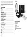 3
3
-
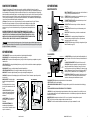 4
4
-
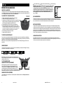 5
5
-
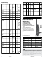 6
6
-
 7
7
-
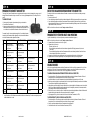 8
8
-
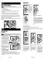 9
9
-
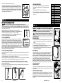 10
10
-
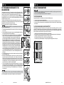 11
11
-
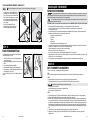 12
12
-
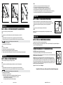 13
13
-
 14
14
-
 15
15
-
 16
16
-
 17
17
-
 18
18
-
 19
19


Ask a question and I''ll find the answer in the document
Finding information in a document is now easier with AI
Related papers
-
SportDOG SDF-CTR-22 Owner's manual
-
-
-
-
-
-
-
-
-
Other documents
-
 Cabela s GS-100 User guide
-
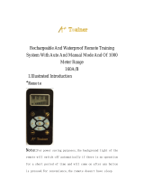 A+ Trainer 160B User manual
-
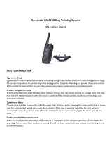 Barkmate BM4200 User guide
-
Sunbeam Bedding SBFNSS1 - User manual
-
Dogtra eF-3000 Gold Owner's manual
-
Sunsun Electronic Technology S-35 Operating instructions
-
Shenzhen DT1200 Operating instructions
-
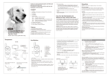 TIZE TZ-812 User guide
-
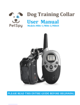 PetSpy M86-2 User manual
-
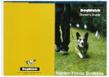 DogWatch 3000 System Owner's manual


