Page is loading ...

AR8/16 ELITE
MANUAL
©Axiom Tool Group, Inc. All rights reserved. Rev. 14/March/2018

2 | A x i o m T o o l G r o u p
Axiom Tool Group, Inc. has provided this manual covering the safe operation and maintenance procedures
for the AutoRoute™ Elite series machines. Contained in the manual are installation instructions, safety
precautions, operational procedures and maintenance guidelines.
The instructions set forth in this document, will ensure that the AutoRoute™ machine will provide
consistent, long-term operation.
This manual was not intended to cover every facet of machine operation. The use of jigs, fixtures, after
market CNC accessories, choice of materials and tooling may require additional research. Online forums, and
CNC blogs are a good source of knowledge from experienced users.
Regardless of the methods in place, personal safety is always a priority.
If you have any questions or comments, please email the Axiom Precision Customer Service team at
support@axiomtoolgroup.com.
The AutoRoute™ is an electrical appliance and precision machine. Protect yourself and your investment. Read and
understand the entire owner's manual before attempting assembly or operation. Read and understand the warnings
posted on the machine and in this manual. Failure to comply with all the warnings may cause serious personal injury
or costly damage to your AutoRoute™.
This AutoRoute™ CNC machine is designed and intended for use by properly trained and experienced personnel
only. If you are not familiar with the proper and safe operation of a CNC machine, do not use the AutoRoute™ until
proper training and knowledge have been obtained.
Your AutoRoute™ machine is intended for cutting wood, acrylics, wood-fiber composites, certain plastics and non-
ferrous metals. Do not use this machine for other than its intended use. If used for other purposes, Axiom disclaims
any real or implied warranty and holds itself harmless from any injury that may result from that use.
Shop Environment
1. Ensure that the floor can bear the weight of the machine and work pieces mounted on it.
2. Keep the floor around the machine clean and free of scrap material, oil and grease.
3. Do not lean lumber or other heavy materials against the gantry, guide rails or table.
4. Support the weight of the dust hose attached to the dust shoe accessory to prevent the weight of the hose
from dislodging the dust shoe. Ensure that there is sufficient slack in the dust collection hose to allow the
spindle to cover the entire work area.
5. Locate the AutoRoute™ away from overhead pipes and plumbing fixtures to prevent condensation from
dripping on to the spoil boards and control system components.
6. Locate the AutoRoute™ away from sinks, faucets or other water supplies or storage to prevent splash-out
that can damage the spoil boards and control system components.
7. Provide adequate room between the AutoRoute™ and other machines in the shop to reduce the chance of
accidental jarring when transporting lumber or other heavy materials through the shop and while materials
are being worked on other machines.
8. Ensure adequate space between machines to allow for the possibility that the work piece will extend over
the end of the AutoRoute™ table.
9. Store cutting tools in a dry location and prevent contact to preserve the cutting edges.
Safety Information

3 | A x i o m T o o l G r o u p
Health and Safety
10. Always wear approved personal health and safety equipment as indicated for the materials and type of
operations that will be performed. These should include a dust mask, hearing protection, safety clothing,
and safety glasses/face shield. Do not rely on prescription or over-the-counter eyeglasses; they are not
safety glasses. Wear ear protectors (plugs or muffs) even during short periods of operation.
11. Before operating this machine; remove any hand, wrist, and neck jewelry and roll sleeves up past the
elbows. Be sure to not wear loose clothing which may become caught in the machine and confine long hair.
a. Non-slip footwear or anti-skid floor strips are recommended.
12. Use a dust mask or other safeguards to avoid inhaling dust generated from wood products. Install dust
collection equipment consistent with shop ventilation practices and budget. Remove dust and debris from
the floor frequently to prevent slipping. Drilling, sawing, sanding or machining wood products generates
wood dust and other substances known to the State of California to cause cancer. Wood products also emit
chemicals known to the State of California to cause birth defects or other reproductive harm. (California
Health and Safety Code Section 56).
13. In addition to other health hazards, dust from wood and other materials is flammable. Do not operate
welding, wood burning, smelting, soldering or other high-heat tools on the AutoRoute™ table or vicinity.
14. Do not operate this machine while tired or under the influence of drugs, alcohol or any medication.
Electrical
15. Make certain the switch is in the OFF position before connecting the machine to the power supply.
16. Make certain the machine is properly grounded and the circuit is protected with a fuse or circuit breaker in
accordance with local codes. Install a separate circuit if necessary to limit power loss when multiple
machines in your shop are operating simultaneously. If necessary, place a cover on the outlet to prevent
accidental disconnection.
17. Perform all machine adjustments or maintenance with the machine unplugged from the power source.
18. Follow effective lockout procedures to reduce the risk from high voltage wires and components and prevent
intentional bypassing of safety controls and accidental operation.
19. Don’t use in a damp or wet location, or expose to rain, fog or snow.
20. Keep the electrical cord away from sharp edges, heat or moving parts, and do not store materials on top of
it. Position the cord so it will not become a tripping hazard.
21. While the use of an extension cord is discouraged, it is recognized that the wiring layout of the shop may not
allow the placement of the AutoRoute™ directly next to an outlet. If it is necessary to use an extension cord,
make sure the extension cord is in good condition, heavy enough to carry the current requirements, and
installed to prevent a tripping hazard. An undersized cord will cause a reduction in voltage resulting in loss of
power and overheating which may result in fire or electrical shock.
Other Safeguards
22. Remove and store adjusting keys and wrenches before turning on the power. If necessary for visibility, apply
safety markings to adjusting wrenches and keys.
23. Install safety guards consistent with general shop safety practices. Keep safety guards in place at all times
when the machine is in use. If removed for maintenance purposes, use extreme caution and replace the
guards immediately after completion of maintenance.
24. Check damaged parts immediately. Before further use of the machine, a guard or other part that is damaged
should be carefully checked to determine that it will operate properly and perform its intended function.
25. Keep visitors a safe distance from the work area. Keep children away.

4 | A x i o m T o o l G r o u p
26. Control liquids in your shop to limit the possibility of spillage that can damage the AutoRoute™ which can
cause damage or personal injury from electric shock or fire. Be careful with storage and use of cleaning
fluids, finishes and solvents. Never use the table to apply or dry finishes.
Maintenance
27. Establish a weekly and monthly maintenance checklist and follow it diligently.
28. Routine maintenance should include periodic checks for alignment of moving parts, looseness or binding of
moving parts, worn or bare wires, breakage of parts, skewed mounting and any other conditions that may
affect its operation or cause injury. Analyze breakage or damage to determine the cause and take
appropriate remedial action.
29. Do not operate the AutoRoute™ if a component of the control system is damaged. It should be properly
repaired or replaced before use.
30. Follow instructions for lubricating and changing accessories.
31. Store maintenance tools and supplies nearby, consistent with shop maintenance practices and resources.
Operational Practice
32. Never leave the machine running unattended. Always be in close reach of the emergency stop button.
33. Turn the power off and do not leave the machine until it comes to a complete stop.
34. Avoid pinch points and entanglement hazards. Keep hands and clothing away from the ball screws, thrust
bearings, gantry, guide rails and rotating cutting tool while in operation.
35. Use the right tool at the correct speed and feed rate. Do not force a tool or attachment to do a job for which
it was not designed. The right tool will do the job better and more safely.
36. Do not touch a cutting tool immediately after use. It will be hot and may cause skin burns. Exercise caution
when handling the collet and spindle nut if the cutting tool is hot. Keep a heavy glove or oven mitt on hand
for the purpose.
37. Do not lay a hot cutting tool on its side. Create a rack for cooling off hot cutting tools.
38. Use recommended accessories; improper accessories may be hazardous.
39. Do not use dull, gummy, or damaged cutting tools. Keep bits and other cutting tools clean and sharp for best
and safest performance.
40. Turn off the machine before cleaning. Use a vacuum, brush or compressed air to remove chips or debris. Do
not use hands.
41. Do not climb or stand on the machine. Serious personal injury and costly damage could occur if the machine
tips over or the gantry is dislodged.
42. Remove loose items and unnecessary work pieces from the table before starting the machine.
43. Plan tool paths to make multiple passes rather than to take off a large amount of material at one time. This
will reduce mechanical stress and heat on cutting tools.
44. Always secure a work piece to the spoil board using clamps, vacuum, or double-sided tape. If the work piece
is mounted in a jig, ensure that the fixture is securely held to the table. Never hold a work piece down by
hand while operating.
45. Inspect the material of your work piece to detect any defects that may result in ejection of large pieces of
scrap.
46. Make sure the work piece is free from nails, hardware, or other foreign objects.
47. After installing a cutting tool, make sure the collet is securely tightened. An unsecured cutting tool may fly
loose from the collet and cause injury. Be sure that the adjusting wrenches have been removed and are
secured before turning on the power.

5 | A x i o m T o o l G r o u p
To avoid accidental or unintended use by young children or others not qualified to use the tool, a padlock may
not be required.
The Elite series CNC machines, feature the use of several Emergency switches.
WARNING: FOR YOUR OWN SAFETY READ INSTRUCTION MANUAL
BEFORE OPERATING TOOL:
To lock out using an Emergency switch on the AR8 Elite:
1. Open the padlock.
2. Insert through hole in the Emergency
switch (need depress this button).
3. Close the padlock.
4. Place the KEY in a safe place out of the
reach of children.
To lock out using the Emergency switch on the AR16 Elite.
1. Depress the Emergency Stop button.
2. Rotate the button counter-clockwise to remove.
3. Store button in safe location (machine remains inoperable until
unlocked).
4. To unlock, reinsert button and rotate clockwise until the Emergency
Stop is released.
Grounding Instructions:
This tool should be connected to a grounded metal permanent wiring system, or to a system having an
equipment-grounding conductor.
Emergency Switch

6 | A x i o m T o o l G r o u p
Section Page
1. Safety Information 2
2. Emergency Switch Padlock 5
3. Router specifications 7
4. Glossary of terms 8
5. Setup and Assembly
5.1. Packaging Contents 11
5.2. Stand assembly 12
5.3. Installing Router 13
5.4. Finishing Machine Assembly 14
6. Electrical Connections 15
7. Post Processor Information 16
8. Operations
8.1. Controller Intro 17
8.2. Operating procedure 18
8.3. HOME Position 18
8.4. Moving Router (Spindle Head) 19
8.5. Setting Work Origin 20
8.6. Programming Additional Origins 22
8.7. Returning to Programmed Origins 22
8.8. Setting Spindle RPM 23
8.9. Processing a File 23
8.9.1. Copying Files to internal Memory 23
8.9.2. Deleting Internal Files 24
8.9.3. Speed Scale Adjustment 24
8.9.4. Pausing During a Tool-path 24
8.9.5. Part Work 25
9. User Defined Controller Settings 26
9.1. Editing User Defined Settings 28
10. Troubleshooting
10.1. Error Messages 29
10.2. Alarm Codes 38
Table of Contents

7 | A x i o m T o o l G r o u p
1
• Supports the standard G code, PLT format instructions; supports domestic and international mainstream CAM software, such
as: Type3, Art cam, UG, Pro / E, Master CAM, Cimatron, Wentai etc.
• Comes with USB communications port, file transfer efficiency can be directly read U disk, card reader file, Plug and Play.
AutoRoute:
8 Elite
16 Elite
X Axis Travel
24" (610mm)
•
48” (1210mm)
•
Y Axis Travel
48" (1220mm)
•
•
Z Axis Travel
8" (200mm)
•
•
Table Work Area
28.5" x 63" (724mm x 1600mm)
•
51"x 69" (1300mm x 1750mm)
•
Collet
ER-20
•
•
Collet Chuck
1/4" and 1/2" Included
•
•
High Speed Spindle
3 HP 2.2kW/7.5A Electro Spindle
•
•
Spindle Speed
0~24000 RPM
•
•
Rapid Feed Rate
320 IPM (8 M/min)
•
•
Precision Linear Guide Rails
X/Y/Z Axis
•
•
Precision Ball Screw
X/Y/Z Axis
•
•
Power Requirements
220V, 50~60 Hz, 15A Single Phase
•
•
Working Table
High Rigidity Interlocking Aluminum
•
•
Integrated MDF Spoil Board
•
•
Gantry Bridge
High Rigidity Aluminum Extrusion
•
•
Gantry Support
Gravity Cast Aluminum Alloy
•
•
Gantry Clearance
8” (200mm)
•
•
Machine Base
Welded Structural Steel Frame
•
•
Machine Footprint
34.5” x 63 (875mm x 1600mm)
•
60" x 75" (1525mm x 1900mm)
•
Required Floor Space
38" x 82" (965mm x 2000mm)
•
70" x 120" (1775mm x 3000mm)
•
Max. Machine Height
62” (1575mm)
•
58” (1475mm)
•
Machine Weight
764lbs (347kg)
•
1420lbs (645kg)
•
Tool Touch Off Puck
Standard Accessory
•
•
Integrated Liquid Cooling System
Standard Accessory
•
•
Controller
1
HUST Industrial 4-Axis Controller
•
•
Specifications

8 | A x i o m T o o l G r o u p
4
th
Axis – An accessory that enables the CNC to operate as a lathe.
Axis – Direction of movement. On a three-axis machine: X (left-right), Y (front-back) & Z (up-down).
Array Work – Division of the machine work surface into square or rectangular work spaces so that the toolpath can
be ran in each space to produce several identical profiles.
Ball End (Ball Nose) – A cutting tool that has a rounded cutting arc, where the arc diameter is equal to the cutting
diameter.
Ball-screw – Drive system component. The ball-screw is rotated by the stepper motor and provided the means for
moving the gantry and spindle along the axes.
Bed – The Bed of the CNC consists of a welded steel frame and an extruded aluminum table top, tongue and groove
table top with integrated T-slots.
CAD – Computer aided design using software to assist in designs
CAM – Computer aided manufacturing using software to define toolpaths and assist in manufacturing processes.
Chip Load – Chip load is the measure of the thickness of a chip a cutter will cut.
CNC – Computer numerical control
Climb Cut – Refers to the relationship of the cutting tool rotation to the direction of feed. A climb cut deflects the
cutting away from the cut, with the direction of the feed.
Collet – A metal collar that holds the cutting tool within a spindle nut.
Conventional Cut – Refers to the relationship of the cutting tool rotation to the direction of feed. A conventional cut
deflects the toward the cut, against the direction of the feed.
Compression Bit – A cutting tool with a combination of up and down shear cutting edges. Typically used for cutting
laminate material to prevent tear-out on both sides of the sheet.
Deflection – Tool deflection occurs when the spindle speed and feed rate exert sufficient force to deflect the cutting
tool. Deflection leads to excessive wear and chatter which can shorten tool life and will leave unwanted tooling
marks on the material.
Down-Shear Bit – A cutting tool whose edges carve downward on the face of the toolpath. Reduces the potential for
tear-out but requires a slower feed-rate.
Drag Knife – A cutting tool that holds a razor or knife blade used to cut and inscribe material. Used with spindle or
router motors turned off, and freely spins as it follows the direction of the tool-path.
Dust Shoe – An accessory which aids in dust collection by limiting the spread of dust and debris by channeling the air
flow through an attached dust collection system.
End-Mill – A cutting tool with a straight end, typically with a spiral flute(s). It creates a channel with a flat bottom
perpendicular to the sides.
Feed and Speed – A combination of factors that must be set to control the work performed by the cutting tool.
Feed-rate – The speed at which the cutting tool moves along a work piece.
Glossary

9 | A x i o m T o o l G r o u p
Flute Length – The length of the cutting portion on a router bit or cutting tool.
Flutes – The cutting edges or inserts of a router bit or cutting tool.
Finish Cut – A 3D tool-path the reduces or eliminates the irregular contours left by the rough cut.
Form Bit – A bit that carves a standard profile such as a round over, ogee or similar contours.
Gantry – The frame structure that straddles the bed and carries the spindle. It moves on guide rails along the length
of the bed and is driven by the ball-screw system.
Gantry Bridge – The part of the gantry that lies between the upright towers. The upper bridge carries the spindle
and cooling system. The lower bridge supports the weight of the gantry and affixes directly to the Y axis ball-screw.
Gantry Upright (Towers) – Parts of the gantry that extend upward, supporting the upper gantry bridge.
G-Code – A machine language that uses axis points and commands which the machine uses to move and perform
functions.
Grid – The minimal movement units of the router. The router head automatically moves to the next grid position
when the directional button is toggled in either continuous or step mode.
HHC – The handheld controller component of the control system.
Hold-down – A clamp or other such device used to firmly hold a workpiece or fixture to the table. Includes clamps,
double-sided tape, vacuum pods and others.
Home Position – Mechanical point set using magnetic limits switches.
MCM – Machine Constant Parameters, allow manufacturer to define certain machine constants to match
specifications of the equipment and machining requirements.
Origin – User designated zero point for the work piece. From which the router will reference the positioning of all
cutting.
Plunge – The distance on the Z axis that the spindle and cutting tool moves toward, into, or along the material.
Plunge Rate – The speed of descent of the spindle on the Z axis.
Pocket Tool-path – A tool-path that creates a cavity in the horizontal surface of a work piece.
Positioning Dial – Small dial, found on the lower right portion of the controller which is used for fine movement of
an axis using a present unit of measurement. Units are selected by using the Function F2 Key when on the Jog Screen
and can be cycled between MPGx100(0.1mm), MPGx10(0.01mm) and MPGx1(0.001mm).
Post Processor – A software function that enables the CAD/CAM application to format G-Code enabling the control
system of a CNC to follow the designated tool-paths.
Profile Tool-path – A tool paths that cuts along the profile of a set of vectors. Typically used to cut out the shape of a
design.
Proximity Switch – A magnetic limit switch that is used to find the HOME position.
Rough Cut – A 3D toolpath where the initial cut is designed to remove unwanted material, leaving a rough contour.
Selection Dial – Small dial, found on the lower left portion of the controller which is used to select one of several
sets of different operations.

10 | A x i o m T o o l G r o u p
Soft Limits – Limits on movement availability. Imposed by the work space boundaries and based on controller
settings and the location of HOME. An “out of soft limits error” implies that based on the positioning of the
workpiece, there is not enough room to move in a designated direction.
Speed Scale – Allows for the reduction of the feed-rate at the beginning of a tool-path to reduce the stress on a
cutting tool as it first contacts the material.
Spindle Speed – Rotational speed of cutting tool (RPM).
Step Down – Distance in Z-axis that the cutting tool plunges into the material.
Step-over – The amount the cutting tool moves away from the previous cutting path as it routes the new path.
Surfacing – The process of leveling the surface of the spoil boards so that they are perpendicular to the spindle.
Tool-path – User defined route which the cutter follows to machine a workpiece.
Touch-Off Puck – A device used to set the zero point (Origin) for the Z axis.
Up-Shear Bit – A cutting tool whose edges carve upward along the face of the toolpath. Increases the potential for
tear-out but allows for a slightly higher feed-rate.
Working Envelope – The three-dimensional area that the spindle can travel within while cutting or milling.

11 | A x i o m T o o l G r o u p
Failure to read and understand all the assembly and setup instructions before attempting assembly may result in
serious injury.
Packaging contents for the Axiom Precision Stand. (AR8 Elite Only)
2-Stand upright (front & back)
2-Cross braces
1-Lower shelf plate
1-Stand hardware package
Hardware package contains:
4-Swivel casters
4-Leveling Feet
4-hex nuts
16-Hex bolts (M8x25)
16-Lock washers (M8)
16-Flat washer (M8)
16-Hex bolts (M6x12)
16-Lock washer (M6)
16-Flat washer (M6)
1-Controller hook
2-Machine screws
(M4x6)
4-Small rubber pads
Remove all contents from shipping boxes. Do not discard carton or packing material until assembly is complete.
Accessories commonly ship inside machine or stand packaging and can be easily over looked.
Tools required for assembly:
#2 Philips-Screwdriver
10mm, 13mm and 17mm sockets and socket wrench
24mm open-end wrench
2mm and 3mm Allen key
Level
Setup and Assembly

12 | A x i o m T o o l G r o u p
Packaging contents for Axiom Precision CNC machines:
1-Router table assembly
1-Electrical control box
1-Hust Industrial handheld controller
1-Controller cable
1-Tool touch-off puck
1-USB Storage device
2-Collet wrenches
1-1/4” ER-20 Collet
1-1/2” ER-20 Collet
4-Rubber bushings (AR8 Model Only)
4-Hex Bolts (M17x45) (AR8 Model Only)
4-Washers (M17) (AR8 Model Only)
4-6 Plastic Caps (Cover Stand Mounting Bolts)
1-2mm Allen Key
Assembling Stand (AR8 Elite Model
Only):
Assembly for the AR8 Elite series machines is the same as Pro+/ Basic machines. The difference being that the stand
and tool-box are included as part of the Elite machine.
1- Thread a (1) loose hex-nut onto each of the (4) leveling feet.
2- Turn the square stand uprights upside down. Do this on top of the
cardboard packaging to prevent scratching.
a. Install the (4) leveling feet and (4) swivel casters using (1) M6 hex
bolt, (1) M6 lock washer, and (1) M6 flat washer for each caster.
Tighten all the caster hardware securely. The leveling feet can be
adjusted later.
b. Rotate uprights so the cross-brace mounting plates are facing each
other. Separate the uprights far enough that the braces can fit
between them.
c. Align the cross-braces between the uprights and bolt the mounting
flanges to the plates using (4) M8 hex bolt, (4) lock washers and (4)
flat washers for each side.
*As seen in the diagram above, the braces should be rotated correctly for the tool-box and shelf to sit at the
correct height. Braces should be mounted so that the top and bottom are the larger flat surfaces*
6- With assistance, the stand can now be flipped over onto the casters and leveling feet.
7- Flip the Shelf upside down and stick (1) of the rubber pads on each corner of the shelf
flange.
a. Install shelf between the braces on the stand, all the way towards the rear.
b. The small rubber pads should now be between the flange and the top surface of
the brace. This will help prevent unwanted movement and scratching.

13 | A x i o m T o o l G r o u p
8- The tool-box will sit to the front of the stand, so be sure to orient the shelf
towards the rear to serve as storage.
a. Turn the tool-box upside down. Install (1) of each hanger on either
side of the toolbox using the installed rivnuts and (2) 3mm cap-
screw each.
b. Insert the tool-box into the stand, from the top. The hangers will
with snugly between the braces on either side of the tool-box.
c. The front can be slid forward to rest within the opening on the
stand upright.
Installing the router table on the Stand:
The CNC router table assembly is heavy. Please use a secure means and use caution when lifting onto the stand.
To avoid damage, be careful to never lift the router by the gantry.
1- If using a forklift, keep forks under the steel frame to avoid damaging the wiring and mechanics of the
machine.
a. Place a scrap piece of lumber beneath the router assembly and carefully slide forks beneath the
steel base.
Make sure the forks extend through to the other side of the machine for safe lifting.
2- Position router over the stand and align holes on router mounting
flanges and stand uprights. Being careful to make sure the stand is
properly oriented with the machine front.
3- Place (1) rubber bushing over the holes in the stand. Lower the
machine to sit on the bushings.
a. Attach the machine to the stand using (1) M10 Hex bolt, (1)
washer at each corner.
b. Insert the bolt/washer through the machine base/mounting
flange and the rubber bushing.
c. Thread the bolt loosely into the stand mounting holes. Do not
tighten until all bolts have been threaded.
d. Remove fork lift and tighten bolts evenly.
4- Place level on the router table, then level the assembled machine by
adjusting the leveling feet. Be sure to level the machine in all
directions.

14 | A x i o m T o o l G r o u p
Finishing machine assembly:
With the machine mounted on the stand, or safely on a secure work surface if a stand was not acquired, now it’s
time to begin finishing the setup.
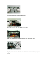
1- Insert the control box into the front right cavity of the tool-box.
a. Power and communication cables will run through the lower hole in the back of the tool-box.
2- Insert the cable connectors into their corresponding female receptacles and twist the collar to tighten. The
receptacles are keyed, so the plugs will only insert one way.
3- Be sure to position the electrical cord through the back of the stand safely, so it will not be damaged by the
castors or become a tripping hazard.
4- Attach the controller cable to the front of the control box. Be careful to not overtighten the screws.
a. Connect the hand-held controller securely to the opposite cable end.
b. When complete the controller can be hung from the Red Hook which ships with the machine.

15 | A x i o m T o o l G r o u p
All Electrical connections must be performed by a qualified electrical and follow any local codes
and ordinances. Failure to comply may result in serious injury.
Electrical connections that are improperly installed or are outside operational specifications may cause machine
damage and void any warranties that are in place.
This machine is rated for 220V +/-10% having an operational range of 200-240V.
The machines come pre-wired with a NEMA 6-20 plug for use on a circuit with a
grounded outlet as pictured. It is recommended that these machines be connected
to a dedicated 15-amp circuit.
If the machine must be reconnected for use with a different type of electric circuit,
the connection must be done by qualified person(s) and must comply with all local
codes and ordinances.
Grounding Instructions:
Axiom CNC machines must be grounded. This grounding provides a path of least resistance for electrical current,
which during a malfunction will reduce the risk of electrical shock.
All Axiom machines are equipped with an electrical cord with grounding conductor and plug. The plug must be used
with a matching outlet that is properly installed and grounded in accordance with local codes and ordinances.
These plugs must not be modified, if a matching outlet is need, one must be installed by a qualified electrician.
Improper installation may result in electrical shock.
If grounding instructions are not completely understood or if in doubt as to whether the
machine is properly grounded, a qualified electrician should be consulted.
Extension Cords:
The use of extension cords should be discouraged. It is recommended to place the machines as near to the power
source as possible.
If an extension cord is necessary, make sure any cord used is in good conditions. Worn or damaged cords should be
replaced immediately.
When using an extension cord, be sure to use one that is heavy enough to carry the required current and use only 3-
wire extension cords that feature the correct 3-prong grounding plugs and 3-pole receptacles.
An undersized cord will cause a drop-in line voltage resulting in loss of power, overheating and runs the risk of
fire.
It is recommended that if an extension cord must be used, it be a 10-12 gauge grounded-three wire cord of no more
than 8-10 feet.
Electrical Connections

16 | A x i o m T o o l G r o u p
With the purchase of a new Axiom Precision Elite Model CNC, there will also be a new Post Processor that will need
to be installed into the VCarve or Aspire software.
Customers should receive along with the tracking information for their order…a link to download this post processor
and instructions from the website.
Be sure when saving tool-path files to use with either Elite Model machine, that the correct post processor is being
selected.
If this file has been received, please contact the Technical Services Department of Axiom Tool Group with the
contact information listed below:
Phone 844-642-4902
Email: support@axiomtoolgroup.com
Or simply download any of our available post processors by visiting: www.axiomprecision.com/post
Available Post Processors for the Axiom Elite AR8/AR16 machines:
Axiom_Elite_CNC => Normal 3-Axis operation of standard VCarve/Aspire tool-path files.
Axiom_Elite_4
th
=> Required for 4
th
Axis machining.
Axiom_Elite_PVC => Required for PhotoVCarve. (Installed into PhotoVCarve only)
Axiom_Elite_Drag => Disables the spindle for Drag Knife/Diamond Bit operations.
Axiom_Elite_Laser =>Required for the Axiom Laser Engraving accessory
To load these Post Processor files: (VCarve or Aspire) *PhotoVCarve uses different instructions*
Open the software, click File and select to Open “Application Data Folder”.
Click and drag, or copy (Crtl+C) and paste (Crtl+V) the files into the PostP folder.
Once you have moved the file …if the software is currently running you will need to close and restart it before it will
appear in the Post Processor list when saving your toolpath/s.
Important Post Processor Info:

17 | A x i o m T o o l G r o u p
Before getting started with the machine, it is recommended to become familiar with the handheld controller for
operation of the machine, setting up a job and processing a file.
Controller:
Toolpaths, that are created in the design software are communicated to the CNC router through the handheld
controller. On the Elite series machines, this is done through the HUST Industrial 4-Axis controller.
Processing tool-paths or jobs, is performed either by using a USB Flash drive (USB2.0 of 8GB or smaller) or from
internal memory.
Internal memory is recommended for jobs of 1 hour run time or longer, and any files that will be used frequently.
The HUST 4-Axis Controller Key pad which is seen here, uses either;
Single Touch Buttons may perform one of many single tasks or if
held down, will perform a task continuously (such as machine
movement).
Function Keys (Top of keypad, just below the screen), which
when selected will perform a few additional tasks. May allow for
a selection process, which will allow settings to be
made/adjusted.
Selection Dial, allows the selection of various sets of controller
features.
Fine Motion Knob, allows small increment movement of
individual axis in 3 different units. 0.1mm, 0.01mm and
0.001mm steps.
Operations

18 | A x i o m T o o l G r o u p
Operating Procedure:
Machine operations may be done several ways; either through the controller keypad or through the design files
(tool-paths) which can be downloaded to the controller through the USB (Udisk) or ran from internal memory.
Before performing an operation:
1- Make sure machine stand leveling feet (if available) have been lowered to prevent the machine from
moving.
2- Ensure that the workpiece is securely held to the table which can be done using any of the following:
a. Clamps
b. Fixtures
c. Vacuum hold-downs (Optional Accessory)
d. Double sided tape
3- Turn on the machine by rotating the green switch to the right. The controller display should light, displaying
the loading screen.
a. The emergency stop button may need released if it has been used.
Once done loading, a HOME operation must be performed before any other function.
HOME Position:
When turning on the machine, once the controller has finished
loading, the following message will be flash at the bottom of the
screen:
“Home First”
As seen in the picture to the right….
At this point, Selection dial should be used to switch to the
HOME screen, if not already there.
Home position is determined by a set of magnetic proximity
sensors, one of which can be found on either end of each axis.
These sensors can be calibrated, however, their position should
not change.
During a HOME operation the following will occur:
1- First the Z axis will raise to the top of the axis travel.
2- Then the X & Y axes will travel, simultaneously, to the front left corner of the machine.
3- When complete the controller display will show 0.00 for all axis under the Machine Coordinate
column.
Coordinate screen will also display the coordinate state the controller is currently using (Number 1-10 in the upper
left corner of the screen) and the Work Coordinate or position of the router in relation to the programmed Origin
(0,0 point).

19 | A x i o m T o o l G r o u p
It is important that a HOME operation is performed at every start-up to ensure that the limit switches and internal
software settings are properly working. All machine movements are software driven and based upon the HOME
position.
Performing a HOME Operation:
The HOME operation can be selected to run from the controller at any time.
This will require that the Selection Dial be turned to the HOME screen. The HOME screen (as seen previously) will
display the current machine and work coordinates.
While any of the axes can be selected, it is recommended that the HOME operation is performed on all Axes at the
same time.
1. Turn Selection Dial to the HOME screen.
2. Press the Function Key F1 (far left side) to select All Axes.
3. Press Start.
Other options would include the use of Function Keys F2-F5 to select individual Axes to HOME.
Use Caution when doing this, as the Z axis may contact fixtures, material and other obstacles if too low.
Other Features of the HOME Screen:
Home Speed-Lists the current speeds for the HOME operation.
These can be adjusted by using the arrows to highlight the
parameter for the desire axis, entering the new number and
pressing ENTER.
When entering the new number, the information being
entered will be temporarily displayed at the bottom of the
screen just above the Function Key titles until the Enter key is
pressed.
Machine Coordinates-These are the absolute positional values
based on the HOME position. Where the coordinates for HOME
are always (0,0).
Work Coordinates-Values that represent the current distance from center of the tooling to the current selected
ORIGIN or (0,0) location.
Icon Status-When any of the axes or parameters are selected, the Icon for that axis or parameter will be highlighted
Blue. On other screens some of the Function Keys will remain selected, while certain functions are being access.
During these times the Function Key titles will be highlighted Black.
Moving Router (Spindle) head:
Once the dial has been rotated to the JOG position. Movement can be made either continuously or in more far
smaller steps.
Continuous and Step movement, both use the internal controller parameter settings to aid in movement and
accuracy.
Continuous movement will depend on the speed selected (Default: Low Speed) and will be accomplished using the
Page Up/Down buttons.

20 | A x i o m T o o l G r o u p
Slow speed- continuous speed that is set at 2000mm/min default.
Fast speed- continuous speed that is set at 6000mm/min default.
Step movement uses a predetermined set of units which can be selected while on the JOG screen. The Function F2
key will cycle between these units (MPGx100=0.1mm, MPGx10=0.01mm, MPGx1=0.001mm), which will allow the
Positioning Dial to be used to make these fine incremental movements.
1- Continuous Movement: Set Selection Dial to JOG. Then select the axis to move by pressing the Function F1
key. The selected axis will be highlighted.
a. Tap or Hold down the Page Up or Down buttons to move any axis, in the positive or negative
direction until the button is released.
i. Use the Shift Lock button to cycle between the
b. The controller will display the location of the router in relation the current Origin (Work Coordinate)
and the Machine Coordinate as it moves.
2- Step Movement: Set Selection Dial to JOG. Then select the axis to move by pressing the Function F1 key. The
selected axis will be highlighted.
a. Use the Positioning Dial to make micro adjustments to any axis, in the positive or negative direction.
i. Function F2 Key can be used to cycle through the units for movement when using the dial.
(MPGx100=0.1mm, MPGx10=0.01mm, MPGx1=0.001mm)
b. The controller will display the location of the router in relation the current Origin (Work Coordinate)
and the Machine Coordinate as it moves.
Setting Work Origin:
Creating an Origin will establish a zero point or reference point
from which the machine will perform the cutting process set in
the tool-path.
The Origin should match the zero point (datum) of the uploaded
toolpath created in the design software.
An Origin for both the X & Y axes and the Z axis need to be set
before beginning operation of a 3-Axis file. Failure to set both
Origins may result in damage to the machine or the cutting
tool.
To set the Origin:
1- Make sure the tooling is properly secured within the collet. Use only ER-20 collets, of the correct size
matching the shaft diameter of the selecting tooling.
a. The machine ships with ¼” and ½” collets (standard sizes for imperial router bits).
2- Move the spindle or router to the desired location using the JOG features mentioned previously.
a. Remember that the controller can be switched between Fast and Slow movement speeds, and the
Step movements can be used to place the bit more accurately for the Origin placement.
b. This location is typically one of the corners of the work material or the exact center point.
3- While on the JOG screen, Press the Function F4 key for ORIGIN SET.
a. With the ORIGIN SET function highlighted, the X & Y axis may be activated (Highlighted Blue)
i. If not, the Z axis will be.
ii. Use the Down Arrow to cycle between the Z axis, or the X & Y axes.
b. With the proper axes activated and the bit in the proper location, Press and Hold the ENTER button
until “Setting Done” is flashed one the screen.
c. The will instantly change the displayed Work Coordinate of the selected axes to 0.00
/