
Intelligent solutions
with lasting effect
Visit devi.com
DEVIreg™ Multi
Installation and User Guide
DEVIreg™ Multi
7 channel DIN-rail programmable controller
EN


Installation and User Guide DEVIreg™ Multi
FEC | Produced by Danfoss © 3
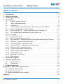
Table of content
1 Introduction .......................................................................4
2 Safety Instructions .................................................................5
3 Mounting Instructions .............................................................5
4 User Manual .......................................................................6
4.1 Control modes overview ....................................................6
4.2 Terms and abbreviations ....................................................7
4.3 General use .............................................................. 10
4.4 Control modes, special functions, special statuses and settings .............15
4.4.1 Active and Not Active Channel status ..................................... 15
4.4.2 Relay status RO/RC – special setting for status ‘Heating On’ ................. 17
4.4.3 1S or Single Sensor mode and Sensor Type set up ......................... 17
4.4.3.1 1S mode ................................................................. 17
4.4.3.2 Sensor Type set up ....................................................... 20
4.4.4 PR or Power Regulation mode ............................................ 21
4.4.5 MOn and MOf – Manually heating On and Manually heating Of mode ......23
4.4.6 CableOK? – special channel function ...................................... 24
4.4.7 Channel ON/OFF – special function ....................................... 26
4.4.8 Device ON/OFF – special function and switch .............................. 27
4.4.9 Relay Test 5/30– special function .......................................... 29
4.4.10 Alarms, alarm data and alarm relay ........................................ 29
4.4.11 Relay Counters view and reset ............................................ 31
4.4.12 Language setting ......................................................... 32
4.4.13 Date and Time settings ................................................... 32
4.4.14 BMS settings ............................................................. 32
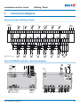
5 Connection diagram ............................................................. 33
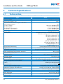
6 Technical Specifications .......................................................... 34
6.1 Technical data ............................................................ 34
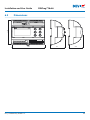
6.2 Dimensions .............................................................. 35
7 Disposal Instruction .............................................................. 36
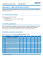
Appendix A. BMS and RS-485 interface .............................................37
A1. Communication settings ......................................................37
A2. RS-485 specifications .......................................................... 37
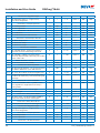
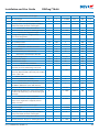
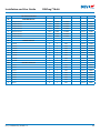
A3. Modbus parameters and variables .............................................37
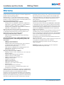
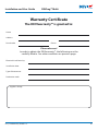
Warranty ............................................................................ 46

Installation and User Guide DEVIreg™ Multi
FEC | Produced by Danfoss ©4
1 Introduction
DEVIreg™ Multi is 7 channel electronic programmable controller to be installed on
DIN-rail and supposed to be used for controlling electrical heating and cooling systems.
Every channel can be individually set up with three control modes –temperature sensor,
time proportional power regulation without sensor and manually on/off with time period.
Universal analog channels’ inputs can be selected via software between 8 types of temperature
sensors including NTC 15 kOhm at 25 °C. Controller has graphic LCD display, Modbus RS-485
opto-insulated serial interface and 110/230 V AC power supply.
DEVIreg™ Multi has 8 control relays – 2 sets of max. 10 A and 6 sets of max. 6 A; and among
them 4 sets NO and 4 sets NC/NO contacts. Relay control functions can be set up for heating
or cooling systems. Additionally, relay contacts are not connected to a voltage source inside
the controller, and can be used for control systems with any voltage up to 250 V AC.
In addition to 3 control modes, DEVIreg™ Multi has some special functions which can be
programmed for every channel: relay status – opened or closed for ‘Heating On’ mode,
channel activation or deactivation, sensor failure alarm, min. and max. temperature alarms,
cable failure monitoring, relay test, channel on/off, relay cycles’ calculator, etc.
Hardware of DEVIreg™ Multi is based on the Danfoss controller type MCX08M2,
art. no. 080G0307, but is customized with special software.
The product complies with the EN/IEC Standard “Automatic electrical controls for house-
hold and similar use”:
• EN/IEC 60730-1 (general)
• EN/IEC 60730-2-9 (thermostat)
More information on this product can also be found at: devi.com
NB: All relevant abbreviations and words in bold are terms used in DEVIreg™ Multi screen
texts with exact the same spelling.

Installation and User Guide DEVIreg™ Multi
FEC | Produced by Danfoss © 5
2 Safety Instructions
Make sure the mains supply to the controller is turned off before installation.
Please also note the following:
• The installation of the controller must be done by an authorized and qualified installer
according to local regulations.
• The controller must be connected to a power supply via an all-pole disconnection switch.
• Always connect the controller to continuous power supply.
• Do not expose the controller to moisture, water, dust and excessive heat.
IMPORTANT: When the controller is used for controlling a floor heating element/cable in
connection with a wooden floor or similar material, always use a floor sensor and never
set the maximum floor temperature to more than 35°C.
Note: Product is designed for Over Voltage Category II. When used in fixed installation,
installation must be equipped with transient protection.
3 Mounting Instructions
Please observe the following placement guidelines:
Install the thermostat in an electric cabinet with DIN rail attachment or a separate DIN
attachment according to local regulation on IP classes.
Do not place the thermostat in a way that it will be exposed to direct sunlight.
Follow the steps below to mount the thermostat:
1. Click the thermostat on the DIN rail attachment.
2. Connect the thermostat according to the connection diagram and chosen system mode(-s)
3. The screen of the heating cable must be connected to the earth conductor of the
power supply cable by using a separate connector.
4. Turn on the power supply.
Note: Always install the floor sensor in a conduit in the floor construction or similar. The
bending radius of the conduit must be min. 50 mm.

Installation and User Guide DEVIreg™ Multi
FEC | Produced by Danfoss ©6
4 User Manual
4.1 Control modes overview
The DEVIreg™ Multi is 7 channels controller and every channel can be individually set up
with one from three control modes:
1. Single sensor control with temperature sensor - ‘1 Sensor’ mode or ‘1S’.
2. Time proportional power regulation – ‘Power Regulation’ mode or ‘PR’.
3. Manually On/Off control with time period – ‘MOn’/’MOf’ mode.
1S mode or Single sensor control
1S mode is control with temperature sensor and adjustable hysteresis. 1S control typically
can be used for Pipe heating, Ground Ice & Snow melting, Cold rooms’ protection, Comfort
Floor heating, Total heating and other applications with temperature control.
This control mode is similar to well-known DEVIreg™ 316 thermostat.
Universal analog channel’s inputs (AI) can be selected via software between 8 types of
temperature sensors including NTC 15 kOhm at 25°C.
This mode can be set up with special function to control Alarm min. and max. temperatures.
Additionally, it can be set up with so called Cable OK? function which uses channel digital
input (DI) with connected Current Monitoring Relay (CMR) to control availability of elec-
tricity passing through a heating cable or similar.
PR mode or Power Regulation control
PR mode is time proportional power regulation with a simple duty cycle generator. Time
for status ‘Heating On’ during the chosen mode cycle can be set up by installer. PR control
typically can be used where one wants to dissipate a subjective amount of power.
This mode is also not connected to a temperature sensor and is therefore very suitable for
installation where it is impossible to install temperature sensor.
This control mode is similar to well-known DEVIreg™ 527 controller.
This mode can be set up with so called Cable OK? function which uses channel digital
input (DI) with connected Current Monitoring Relay (CMR) to control power consumption
or similar.

Installation and User Guide DEVIreg™ Multi
FEC | Produced by Danfoss © 7
Manually On/Of mode
Manually On/Of mode (on the screen – MOn or MOf) is control with setting time period
during which relay status ‘Heating On’ or ‘Heating Of’ will operate.
NB: This mode can be used only on the base of 1S or PR modes and upon its completion controller
returns to the same mode from which it started.
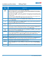
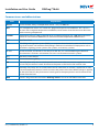
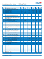
4.2 Terms and abbreviations
NB: Terms and abbreviations in the bold are special DEVIreg™ Multi words used for screen
texts, menu lines, etc.
Special terms and abbreviations
Term in
English
Explanation
#1, #2, …, #7 Channel number from 1 to 7.
1S Single Sensor or ‘1 Sensor’ control mode.
The mode with temperature sensor and adjustable hysteresis.
PR Power Regulation control mode.
The time proportional power regulation with a simple duty cycle generator with time set
when heating is turned on during the chosen period/cycle time.
MOn
MOf
Manually On/Of control mode.
The mode with relay setting either for state ‘Heating On’ or ‘Heating Of’ and time setting
during which this mode will be performed.
Heating On
Heating Of
The state when control algorithm decides to start heating or to stop heating.
On
Of
Special abbreviation used for state ‘Heating On’ or ‘Heating Of’.
It’s a logical state not corresponding to relay status with closed or
opened contacts. When con-
trol algorithm activates heating, it appears
on the screen as On. For this case relay contacts can
be either with an opened circuit state or with a closed-circuit condition which are determined
by the setting Relay status RO/RC – Relay Opened (RO) or Relay Closed (RC).
NB: These abbreviations – On or Of – should be used with 1
st
capital and 2
nd
small letters, and
contain 2 letters only.
RO
RC
Relay status RO/RC for state Heating On – Relay Opened (RO) or Relay Closed (RC).
For the heating mode on, the corresponding state of the relay contacts can be selected –
open or closed. This relay status allows to implement both heating and cooling control, as
well as electric and water heating systems.

Installation and User Guide DEVIreg™ Multi
FEC | Produced by Danfoss ©8
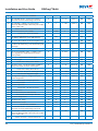
Term in
English
Explanation
ON
OFF
Used for setting Channels or Device with status ON or OFF.
When Channel or Device is set up with OFF – it means that the appropriate control algo-
rithm(-s) is stopped. It is similar to power supply off, but device/channels are still powered,
and display shows some data and settings.
When the Channel is OFF – symbol hash – ‘#” appears in the Channel’s line on the Main Screen.
When the Device is OFF – one or two symbols hash – ‘#’ or ‘##’, appear on the top-left position
of a Main Screen.
NB: The abbreviations ON and OFF should to be used with capital letters only. It emphasizes the
difference in relation to abbreviations On and Of used for Heating status.
# The symbol “Hash sign” indicates when Channel is OFF or Device is OFF. This status can be
set up via Main Menu.
## These 2 hash symbols appear when Device is OFF. This status can be set up by ‘mechanical’
switch on input DI8 when contacts are closed.
En
Dis
En means Enabled and Dis – Disabled, are used to allow of forbid some special functions or
statuses.
Active Possible status for every Channel. When Active = Yes – Channel’s algorithm works according
to the settings and data is displayed on the screen(-s). When it’s not Active or Active = No –
Channel does not work at all and “empty” line appears on the Main Screen.
Yes
No
Status of some settings. For example, Channel can be Active or not Active – it means Yes or
No respectively for settings Activate #1-7.
CableOK?
Special abbreviation used for function checking the proper functioning of the heating cable by con-
dition on digital inputs DI1-DI7. For this purpose, additional device can be recommended – Current
Monitoring Relay (CMR) or so on. For OK and not OK are used terms Ye s and No respectively.
! This symbol appears in Alarm conditions with some Channel(-s).
!!! These 3 symbols appear in Alarm conditions with Device by any reason.
Main Screen The Main Screen displays the main data of controller and the status of all Channels at the
same time. This screen is constantly visible on the display during everyday work.
AI1-AI8 Analog inputs, used for connection of temperature sensors.
DI1-DI8 Digital inputs, voltage free contacts. DI1-DI7 are used for connection of special devices for
function Cable OK?, DI8 is used for connection of ‘mechanical’ switcher for Device ON/OFF
function.
DO1-DO8 Digital outputs connected to relay contacts. DO1-DO7 are used for loads, DO8 – for Alarm.

Installation and User Guide DEVIreg™ Multi
FEC | Produced by Danfoss © 9
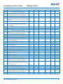
Common terms and abbreviations
Term Explanation
Sensor In this content, always a temperature sensor – NTC, PT1000, etc..
NTC NTC temperature sensor. NTC stands for “Negative Temperature Coefficient”. NTC sensor is
resistor with a negative temperature coefficient, which means that the resistance decreases
with increasing temperature.
PT1000
Temperature sensor. PT refers to that the sensor is made from Platinum (Pt). 1000 refers to that at 0°C
sensor has a resistance of 1000 Ohms (Ω). Sensor has Positive Temperature Coefficient (PTC).
RTC Real Time Clock
BMS A building management system (BMS), is a computer-based control system installed in build-
ings that controls and monitors the building’s mechanical and electrical equipment such as
ventilation, lighting, power systems, fire systems, and security systems.
RS-485 RS-485 or RS485, also known as TIA-485(-A) or EIA-485, is a standard defining the electrical
characteristics of drivers and receivers for use in serial communications systems.
RCD Residual-current device
CMR Current Monitoring Relay
NO
Normally Open relay. Has an initial opened circuit state when no current is applied to its coil
so basically the internal switch disconnects the power to the load in the inactive state.
NC Normally Close relay. Has an initial closed-circuit state when no current is applied to its inter-
nal coil therefore the internal switch connects the power to the load. When voltage is applied
to the coil of the NC relay the internal switch goes to the open position and disconnects the
power from the load.
MCX Danfoss Programmable Controller. DEVIreg™ Multi is based on MCX08M2 controller

Installation and User Guide DEVIreg™ Multi
FEC | Produced by Danfoss ©10
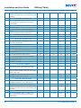
4.3 General use
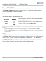
The DEVIreg™ Multi is operated via 4 buttons out of 6. Display with an alpha numeric
style with information in various languages.
Buttons
The functions of the 4 operated buttons are:
Up, Down
Next menu entry / next line / next setting parameter /
shows additional screens
Escape Escape to upper level of menu / show Alarm screen
Enter Confirm / select / go to the Main menu
Besides the normal function of the buttons, some special combinations are important to
the user:
• For quick changing of any values, e.g. temperature – hold button Up or Down.
• Return to Main Screen – press several times Escape or do not press any button during
some minutes.
Display
The DEVIreg™ Multi can simultaneously control up to 7 different systems with 3 different
control
modes. These 7 systems are referred as Channel #1, Channel #2, … and Channel #7.
The DEVIreg™ Multi provides the user with an opportunity to view the current status of
the all systems / channals. This status can be shown in different ways.

Installation and User Guide DEVIreg™ Multi
FEC | Produced by Danfoss © 11
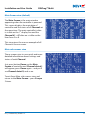
Main Screen view (default)
The Main Screen is the main window
appearing when the controller is powered.
This screen displays the main data of
controller and the status of all Channels at
the same time. The main controller’s data
is visible on the 1
st
display line and the
Channel #1 – #7 data are visible on the
lines from 2 to 8.
This view gives the user an example of all
Channels on one screen.
Main sub-screens view
These screens give to user quick and more
detailed information about settings and
status of each Channel.
Just press button Down on the Main
Screen of controller and Channel data #1
will appear, press Down again – and you’ll
see Channel data #2, and so on.
To exit from Main sub-screens view and
return to the Main Screen – press Escape
2 times.

Installation and User Guide DEVIreg™ Multi
FEC | Produced by Danfoss ©12
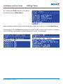
Relay On cycles view
By pressing button Up in the Main Screen
of controller, it gives information about
how many times relays were switched to
status Heating On. This screen is named
Relay On cycles.
Alarms view
By pressing Escape button from Main
Screen – screen(-s) with Alarm appears.
If more than 1 Alarm is happened – use
navigation by going Up/Down. Pressing
Escape button again leads from Alarm to
Main Screen.
Menu system
By pressing Enter from the Main Screen–
screen with Main Menu appears.
The menu system is navigated from Main
Screen by the following sequence:
EN: Enter – Down/Up – Enter – Down/
Up – Enter – … .
EN: Enter – Down/Up – Enter – Down/
Up – Enter – … .
Pressing Escape button mostly leads to a
transition to upper level.

Installation and User Guide DEVIreg™ Multi
FEC | Produced by Danfoss © 13
By scrolling the Down button you’ll get to
the bottom part of Main Menu.
Menu windows above display the root directory of the menu tree or so-called Main Menu.
Activating any line by Enter button leads to a transition to a lower level of menu, opening
a list of settings, parameters, special functions or so on. For example:

Installation and User Guide DEVIreg™ Multi
FEC | Produced by Danfoss ©14
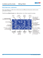
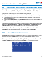
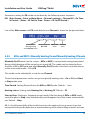
Main Screen view – explanation
The screen below is visible close to the maximum different information which can be
presented on display.
The following Main Screen texts, abbreviations, icons have a special meaning:
Lines with data for
Active Channels #1-#7
Line with mode
Manually Of
over mode PR with
the remaining time
in 57 min.
Line with mode
Manually On
over mode 1S with
the remaining time
in 133 min.
Line with mode PR
with set up cycle time
180 min. and
Heating On status
during 120 min.
The real time after
begining of the cycle
is 113 minutes
Channel OFF
Channel
with Alarm
Sensor fault – open
or short circuit,
or not connected
Device
Time
Degrees
in Celsius
Device
Alarm
Sofware
version
Regulation
type
Real Temp.
on the
sensor for
1S mode
Heating
status
Set up
Temp.

Installation and User Guide DEVIreg™ Multi
FEC | Produced by Danfoss © 15
4.4 Control modes, special functions, special statuses and settings
Each of 7 Channels has possibility to be individually set up with one of three control
modes – 1S (1 Sensor), PR (Power Regulation) and MOn/MOf (Manually On/Of).
The controller configurations for these 3 modes are the following:
1. Single sensor control with temperature sensor or 1S: one temperature sensor input,
one relay output;
2. Power regulation control or time proportional power regulation or PR: no sensor
input, one relay output;
3. Heating control Manually On and Manually Off with setting time period or MOn and
MOf: no sensor input, one relay output;
Together with any control mode could be set up or enabled/disabled some special functions
and statuses: “Relay status RO/RC”, “ CableOK?”, “ Relay test 5/30”, “ Channel ON/OFF” and
“Device ON/OFF”. Special functions and statuses are specified in chapters below.
Additionally, any Channel can be set up with status ‘not Active’ or Active = No. It means
Channel does not work at all and “empty” line appears on the Main Screen.
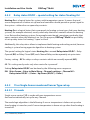
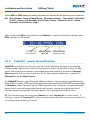
4.4.1 Active and Not Active Channel status
Not Active status can be used for applications there is no need to use full channel set of 7.
And view/line for the Channel which is not used is simply deleted from the screen.
By the way, standard factory setting for DEVIreg™ Multi supposes 1 active Channel #2.
The Main Screen with the only one Active Channel #2 is as on the picture below:

Installation and User Guide DEVIreg™ Multi
FEC | Produced by Danfoss ©16
Activation or deactivation can be done by the following menu sequence:
EN: Main Screen – Enter to Main Menu – Channels settings – Activate channels –
Activate #X
1)
– { Enter – Up/Down (YES/NO) – Enter }
2)
1)
– here and further #X means any Channel number in diapason from #1 to #7.
2)
– here and further brackets indicate more detailed sequence.
EN: Main Screen – Enter to Main Menu – Channels settings – Activate channels –
Activate #X1) – { Enter – Up/Down (YES/NO) – Enter }
Example of the base screens for the sequence above:

Installation and User Guide DEVIreg™ Multi
FEC | Produced by Danfoss © 17
4.4.2 Relay status RO/RC – special setting for status ‘Heating On’
Heating On is a logical status for systems with temperature sensor. It means that real
sensor temperature is below set up level and controller should provide a special signal to
the system – either close or open relay contacts.
Heating On is a logical status that corresponds to heating system type. And some heating
systems, for example electrical, mostly need relay that closes contacts when the heating
is on. But another heating systems, for example water based, sometimes need relay that
opens contacts when the heating is on. For this purpose, DEVIreg™ Multi has possibility
to set up relay status for heating – ‘open’ or ‘close’.
Additionally, this relay status allows to implement both heating and cooling control, because
cooling is system having opposite algorithm to heating system.
The special setting for logical status Heating On is named Relay status RO/RC – Relay
Opened (RO) or Relay Closed (RC) each Channel Relay can be separately set up to status.
Factory setting – RC for relays or relays contacts which are normally opened (NO).
NB: This setting mostly works only when controller is powered!
Setting Relay status RO/RC can be done by the following menu sequence:
EN: Main Screen – Enter to Main Menu – Channels settings – Channel #X –
Relay status RO/RC – { Enter – Up/Down (RO/RC) – Enter }
EN: Main Screen – Enter to Main Menu – Channels settings – Channel #X – Relay
status RO/RC – { Enter – Up/Down (RO/RC) – Enter }
4.4.3 1S or Single Sensor mode and Sensor Type set up
4.4.3.1 1S mode
Single sensor control (1S) is mode with one temperature sensor.
And can be individually set up for any Channel.
The mode logic algorithm is the following: if sensor temperature is below set up value
then heating is turned on, and if sensor temperature is above set up value then heating is
turned off.

Installation and User Guide DEVIreg™ Multi
FEC | Produced by Danfoss ©18
Setting 1S mode can be done by the following menu sequence:
EN: Main Menu – Channels settings – Channel #X – Regulation Type –
{ Enter – Up/Down (1S/PR) – Enter }
EN: Main Menu – Channels settings – Channel #X – Regulation Type – { Enter – Up/
Down (1S/PR) – Enter }
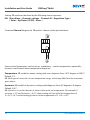
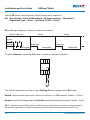
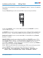
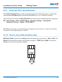
Common Channel diagram for 1S mode is shown on the picture below:
Channel #1
COM
DI 1
C 1
NO 1
AI 1
Some control parameters can be set up: mandatory – control temperature, optionally –
hysteresis and control alarm temperature diapason.
Temperature. 1S mode has temp. setting with max. diapason from -50°C degree to 200°C.
Default: 5°C.
NB: Each type of sensor has its own temperature range, which may differ from the maximum
given above.
Hysteresis.1S mode has hysteresis setting with diapason from 0,2 degree to 9 degree.
Default: 0,4°C.
NB: Hysteresis is used as the plus or minus value to the set temperature. For example, if
set temp. = 5°C and hysteresis = 0,4°C, then heating will turn off at the temperature of
5 + 0,4 = 5,4°C and accordingly turn on at the temperature of 5 – 0,4 = 4,6°C.

Installation and User Guide DEVIreg™ Multi
FEC | Produced by Danfoss © 19
Setting Temperature and Hysteresis can be done by the following menu sequence:
EN: Main Screen – Enter to Main Menu – Channels settings – Channel #X –
Temp & Hysteresis – #X Set temperature – { Down – #X Set +-Hysteresis }
EN: Main Screen – Enter to Main Menu – Channels settings – Channel #X – Temp &
Hysteresis – #X Set temperature – { Down – #X Set +-Hysteresis }
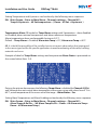
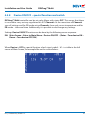
Temperatures Alarm. 1S mode has Temp Alarm settings with 3 parameters – alarm Enabled
or Disabled, alarm minimal temperature and alarm maximum temperature.
Alarm temperatures have unchangeable hysteresis 0,2°C.
Default – Temp Alarm is Disabled, Alarm min Temp = 0°C, Alarm max Temp = 60°C.
NB: It is the full responsibility of the installer/user to set correct alarm values that correspond
to the sensor type and for the specific application to avoid overheating of the cable, building
materials and so on.
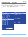
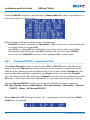
Example of data for Temp Alarm settings and temperature Alarm Status is presented on
the screen below (lines 2-4):
Data on the picture above means the following: Temp Alarm is disabled for Channel #2 (Dis)
and Software does not control alarm temperature, alarm range set up with values from 0 °C to
60 °C, actual temperature of the sensor out of the range – Alarm Status = Ye s .
Setting Alarm Temperatures and Alarm Enabling can be done by the following menu sequence:
EN: Main Screen – Enter to Main Menu – Channels settings – Channel #X –
Alarm Temps & En/Dis – ( #X Alarm Temp En/Dis – Down – #X Alarm min Temp –
Down – #X Alarm max Temp }
EN: Main Screen – Enter to Main Menu – Channels settings – Channel #X – Alarm
Temps & En/Dis – ( #X Alarm Temp En/Dis – Down – #X Alarm min Temp – Down
– #X Alarm max Temp }

Installation and User Guide DEVIreg™ Multi
FEC | Produced by Danfoss ©20
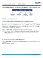
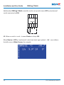
Line of the Main screen with 1S mode data for one Channel is shown on the picture below:
Channel
number
Real sensor
Temp.
Heating
status: On or Of
Set up
Temp.
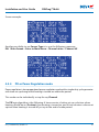
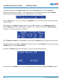
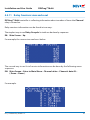
4.4.3.2 Sensor Type set up
1S control mode can be set up with different 8 types of temperature sensors.
Sensor unit can be selected via software connected to Channel’s analog inputs AI1-AI7 between:
NTC15k (15 kOhm @ 25 °C), NTC10k (10 kOhm @ 25 °C), NTC5k (5 kOhm @ 25 °C), NTC2k
(2 kOhm @ 25 °C), NTC100 (100 kOhm @ 25 °C), NTC16k (16,7 kOhm @ 100 °C), PT1000
(1000 Ohm @ 0 °C), Ni100 (100 Ohm @ 0 °C).
Setting of Sensor type can be done by the following menu sequence:
EN: Main Screen – Enter to Main Menu – Channels settings – Channel #X – Sensor
type –
{Enter – Up/Down ( PT1000/ NTC10k/ NTC100/ Ni100/ NTC2K/ NTC16k/
NTC5k/ NTC15k) }
EN:
Main Screen – Enter to Main Menu – Channels settings – Channel #X – Sensor
type –
{Enter – Up/Down ( PT1000/ NTC10k/ NTC100/ Ni100/ NTC2K/ NTC16k/
NTC5k/ NTC15k) }
NB: Setting is possible/visible for Active Channels only.
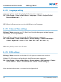
Chosen Sensor type can be found in the Channel Data screens with the following menu
sequence:
EN: Main Screen – Down.
EN: Main Screen – Down.
Page is loading ...
Page is loading ...
Page is loading ...
Page is loading ...
Page is loading ...
Page is loading ...
Page is loading ...
Page is loading ...
Page is loading ...
Page is loading ...
Page is loading ...
Page is loading ...
Page is loading ...
Page is loading ...
Page is loading ...
Page is loading ...
Page is loading ...
Page is loading ...
Page is loading ...
Page is loading ...
Page is loading ...
Page is loading ...
Page is loading ...
Page is loading ...
Page is loading ...
Page is loading ...
Page is loading ...
Page is loading ...
-
 1
1
-
 2
2
-
 3
3
-
 4
4
-
 5
5
-
 6
6
-
 7
7
-
 8
8
-
 9
9
-
 10
10
-
 11
11
-
 12
12
-
 13
13
-
 14
14
-
 15
15
-
 16
16
-
 17
17
-
 18
18
-
 19
19
-
 20
20
-
 21
21
-
 22
22
-
 23
23
-
 24
24
-
 25
25
-
 26
26
-
 27
27
-
 28
28
-
 29
29
-
 30
30
-
 31
31
-
 32
32
-
 33
33
-
 34
34
-
 35
35
-
 36
36
-
 37
37
-
 38
38
-
 39
39
-
 40
40
-
 41
41
-
 42
42
-
 43
43
-
 44
44
-
 45
45
-
 46
46
-
 47
47
-
 48
48


DEVI 140F1139 Installation guide
- Type
- Installation guide
- This manual is also suitable for
Ask a question and I''ll find the answer in the document
Finding information in a document is now easier with AI
Related papers
-
Danfoss 140F1070 Operating instructions
-
-
DEVI reg 330 Electronic Thermostat Installation guide
-
DEVI 140F1032 User guide
-
DEVI 19121445 Installation guide
-
-
-
-
Danfoss 140F1041 User guide
-
Danfoss 140F1055 Installation guide
Other documents
-
Danfoss devireg 530 Installation guide
-
Danfoss DEVIreg 330 Installation guide
-
-
Danfoss 140F1085 Installation guide
-
-
 ThermoMart DWH7016V Owner's manual
-
-
-
-
