
Version 2.0 2009.6
www.lenovo.com
3000 H Hardware Replacement Guide
3103xxxx
Version 2.0 2009.7
31039394
31039394_3000 H_HRG_FM_EN_V2.0.i1 1 2009.7.14 4:19:16 PM

Hardware Replacement Guide
31039394_3000 H_HRG_EN_V2.0.indd1 1 2009.7.14 4:15:25 PM

Contents
Overview ..................................................................................... 1
Chapter 1
Locations ................................................................. 3
Locating components ...................................................................3
Locating connectors on the front of the computer .........................4
Locating connectors on the rear of the computer ..........................5
Identifying parts on the system board ...........................................6
Chapter 2 Replacing hardware .............................................. 12
Removing the computer cover ....................................................12
Removing and replacing the front bezel .......................................13
Replacing a memory module ......................................................15
Replacing the hard disk drive ......................................................16
Replacing an optical drive ...........................................................18
Replacing the keyboard ..............................................................19
Replacing the mouse ..................................................................20
Replacing the External speaker ...................................................21
Completing the installation ..........................................................21
Appendix. ................................................................................. 25
31039394_3000 H_HRG_EN_V2.0.indd2 2 2009.7.14 4:15:26 PM

1
Hardware Replacement Guide
Overview
This guide is intended to be used by customers who are replacing Customer
Replaceable Units (CRUs) as well as trained service personnel who are replacing
Field Replaceable Units (FRUs). In this guide, CRUs and FRUs will often be referred
to as parts.
Note: Trained service personnel should refer to the Hardware Maintenance
Manual (HMM) for parts ordering information.
This guide does not include procedures for all parts. It is expected that cables,
switches, and certain mechanical parts can be replaced by trained service
personnel without the need for step-by-step procedures.
Note: Use only parts provided by Lenovo™.
The description of the TV card in this manual is only used for the machines which
have the TV card. It is invalid for those machines which do not have TV card.
This guide contains procedures for replacing the following parts:
• Memory modules
• Hard disk drive
• Optical drive
• Keyboard
• Mouse
• External Speakers
• Data Cable
Safety information for replacing CRUs
Do not open your computer or attempt any repair before reading the “Important
safety information” in the Safety and Warranty Guide that was included with your
computer. If you no longer have this copy of the Safety and Warranty Guide, you
can obtain one online from the Support Web site at
http://consumersupport.lenovo.com
Additional information resources
If you have Internet access, the most up-to-date information for your computer is
available from the World Wide Web.
31039394_3000 H_HRG_EN_V2.0.indd1 1 2009.7.14 4:15:26 PM

2
Hardware Replacement Guide
You can find the following information:
• CRU removal and installation information
• Publications
• Troubleshooting information
• Parts information
• Links to other useful sources of information
To access this information, go to http://consumersupport.lenovo.com.
Tools required
To replace some parts in your computer, you will need a flat-blade or Phillips
screwdriver. Additional tools might be needed for certain parts.
Handling static-sensitive devices
Static electricity, although harmless to you, can seriously damage computer
components.
When you are replacing a part, do not open the static-protective package
containing the new part until the defective part has been removed from the
computer and you are ready to install the new part.
When you handle parts and other computer components, take these precautions
to avoid static-electricity damage:
• Limit your movement. Movement can cause static-electricity to build up around
you.
• Always handle parts and other computer components carefully. Handle
adapters, memory modules, system boards, and microprocessors by the
edges. Never touch any exposed circuitry.
• Prevent others from touching the parts and other computer components.
• Before you replace a new part, touch the static-protective package containing
the part to a metal expansion-slot cover or other unpainted metal surface on the
computer for at least two seconds. This reduces static electricity in the package
and your body.
• When possible, remove the new part from the static-protective packaging, and
install it directly in the computer without setting the part down. When this is not
possible, place the static-protective package that the part came in on a smooth,
level surface and place the part on it.
• Do not place the part on the computer cover or other metal surface.
31039394_3000 H_HRG_EN_V2.0.indd2 2 2009.7.14 4:15:26 PM

3
Hardware Replacement Guide
Locations
Chapter
This chapter provides illustrations to help locate the various connectors, controls
and components of the computer. To remove the computer cover, refer to
“Removing the computer cover”.
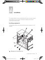
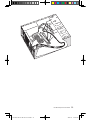
Locating components
The following illustration will help you to locate the various components in your
computer.
Microprocessor fan and heat sink
31039394_3000 H_HRG_EN_V2.0.indd3 3 2009.7.14 4:15:29 PM

4
Hardware Replacement Guide
Memory modules
PCI Express adapter card
PCI Express adapter connectors
Power supply
System fan
Optical drive
Hard disk drive
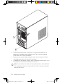
Locating connectors on the front of the computer
The following illustration shows the location of connectors on the front of the
computer.
Power button
USB connector
Headphone connector
Microphone connector
Memory Card Reader (some models are equipped with this connector).
Note: Some models are not equipped with CD drive.
31039394_3000 H_HRG_EN_V2.0.indd4 4 2009.7.14 4:15:31 PM

5
Hardware Replacement Guide
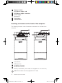
Locating connectors on the rear of the computer
The following illustration shows the location of connectors on the rear of the
computer.
The following illustrations show connections located at the rear of some computer
models. The locations of connectors on your computer will be similar to, but
possibly not identical to these. Following the illustrations is a key that explains the
symbol callouts used in the figures.
Voltage selection switch (Some models are equipped with this switch)
Power connector
PS/2 keyboard connector
PS/2 mouse connector
Serial connector
31039394_3000 H_HRG_EN_V2.0.indd5 5 2009.7.14 4:15:33 PM

6
Hardware Replacement Guide
On-board VGA connector ( Some models are equipped with this connector )
USB connectors
Ethernet connector
Microphone connector
Audio line-out connector
Audio line-in connector
PCI Express x16 graphics adapter connector (Some models are equipped
with this connector. For more information about the graphics adapter, see
the description below).
WiFi antenna connector (This connector only equipped on the model with
WiFi card. For more information about this connector, see WM600-B-LO
Wireless 802. 11b/g Wireless PCI-E Adapter Card User Manual.)
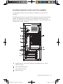
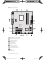
Identifying parts on the system board
The system board (sometimes called the planar or motherboard) is the main circuit
board in your computer. It provides basic computer functions and supports a
variety of devices that are factory-installed or that you can install later.
The following illustrations show the locations of parts on the system board (Only
one of below system board was preinstalled on your computer.).
31039394_3000 H_HRG_EN_V2.0.indd6 6 2009.7.14 4:15:34 PM

7
Hardware Replacement Guide
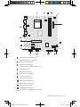
Microprocessor and heat sink
Microprocessor fan connector
Memory connectors(2)
Memory connectors(2)
Thermal sensor header connector
Power connector
Power fan connector
SATA IDE connectors(4)
E-SATA connector
Front panel connector
Front USB connectors(2)
Serial (com2) connector
Front audio connector
PCI adapter connector
PCI Express x1 adapter connectors(2)
31039394_3000 H_HRG_EN_V2.0.indd7 7 2009.7.14 4:15:36 PM

8
Hardware Replacement Guide
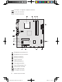
PCI Express x16 graphics adapter connector
System fan connector
12V power connector
Microprocessor and heat sink
Microprocessor fan connector
Memory connector 1
Memory connector 2
Power connector
SATA connectors (4)
Front panel connector
Front USB connectors (2)
Serial (com2) connector
Front audio connector
PCI adapter connector
31039394_3000 H_HRG_EN_V2.0.indd8 8 2009.7.14 4:15:37 PM

9
Hardware Replacement Guide
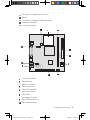
PCI Express x1 adapter connectors (2)
Battery
PCI Express x16 graphics adapter connector
System fan connector
12v power connector
12v power connector
Microprocessor
Memory connector
Power connector
Front panel connector
SATA connectors (2)
Clear CMOS
PCI adapter connector
Front USB connectors (2)
Front audio connector
31039394_3000 H_HRG_EN_V2.0.indd9 9 2009.7.14 4:15:40 PM

10
Hardware Replacement Guide
System fan connector
Microprocessor fan connector
Microprocessor and heat sink
Memory connector 1
Memory connector 2
IDE connector
Power connector
SATA connectors (4)
Front panel connector
Front USB connectors (2)
Battery
Clear CMOS
31039394_3000 H_HRG_EN_V2.0.indd10 10 2009.7.14 4:15:41 PM

11
Hardware Replacement Guide
Front audio connector
PCI adapter connector (2)
PCI Express x16 graphics adapter connector
PCI Express x1 adapter connectors
System fan connector
12v power connector
31039394_3000 H_HRG_EN_V2.0.indd11 11 2009.7.14 4:15:42 PM

12
Hardware Replacement Guide
Attention
Do not remove the computer cover or attempt any repair before reading the
“Important safety information” in the Safety and Warranty Guide that was
included with your computer or in the Hardware Maintenance Manual (HMM)
for the computer. To obtain copies of the Safety and Warranty Guide or
HMM, go to the Support Web site at
http://consumersupport.lenovo.com
Note: Use only parts provided by Lenovo.
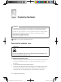
Removing the computer cover
Important
Turn off the computer and wait 3 to 5 minutes to let the computer cool
before removing the computer cover.
To remove the computer cover:
1. Before removing any media (diskettes, CDs, or memory cards) from the drives,
shut down your operating system, turn off all attached devices, and the
computer.
2. Unplug all power cords from electrical outlets.
3. Disconnect all cables attached to the computer. This includes power cords,
input/output (I/O) cables, and any other cables that are connected to the
computer. Refer to “Locating connectors on the rear of the computer”.
Replacing hardware
Chapter
31039394_3000 H_HRG_EN_V2.0.indd12 12 2009.7.14 4:15:42 PM

13
Hardware Replacement Guide
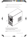
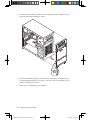
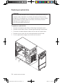
4. Remove the two screws that secure the computer cover at the rear of the
chassis.
5. Slide the computer cover to the rear of the chassis to remove.
Note: For this procedure, it helps to lay the computer on its side.
Removing and replacing the front bezel
To remove and replace the front bezel:
1. Remove the computer cover. Refer to “Removing the computer cover”.
Note: For this procedure, it helps to lay the computer on its side.
31039394_3000 H_HRG_EN_V2.0.indd13 13 2009.7.14 4:15:44 PM

14
Hardware Replacement Guide
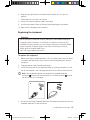
2. Remove the front bezel by releasing the three plastic tabs inside the chassis
and push the bezel outward as shown.
3. To reinstall the bezel, align the plastic tabs on the bottom of the bezel with
the corresponding holes in the chassis, and then snap it into position at the
bottom and top of the chassis.
4. Refer to the “Completing the installation”.
31039394_3000 H_HRG_EN_V2.0.indd14 14 2009.7.14 4:15:47 PM

15
Hardware Replacement Guide
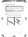
Replacing a memory module
Attention
Do not remove the computer cover or attempt any repair before reading the
“Important safety information” in the Safety and Warranty Guide that was
included with your computer or in the Hardware Maintenance Manual (HMM)
for the computer. To obtain copies of the Safety and Warranty Guide or
HMM, go to the Support Web site at
http://consumersupport.lenovo.com
To replace a memory module:
1. Remove the computer cover. Refer to “Removing the computer cover”.
Note: For this procedure, it helps to lay the computer on its side.
2. Locate the memory module connectors. Refer to “Locating components”.
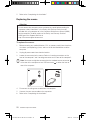
3. Remove the memory module being replaced by opening the retaining clips as
shown.
31039394_3000 H_HRG_EN_V2.0.indd15 15 2009.7.14 4:15:48 PM

16
Hardware Replacement Guide
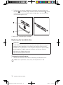
4. Position the new memory module over the memory connector. Make sure
the notch on the memory aligns correctly with the connector key on the
system board. Push the memory module straight down into the connector
until the retaining clips close.
5. Refer to the “Completing the installation”.
Replacing the hard disk drive
Attention
Do not remove the computer cover or attempt any repair before reading the
“Important safety information” in the Safety and Warranty Guide that was
included with your computer or in the Hardware Maintenance Manual (HMM)
for the computer. To obtain copies of the Safety and Warranty Guide or
HMM, go to the Support Web site at
http://consumersupport.lenovo.com
To replace the hard disk drive:
1. Remove the computer cover. Refer to “Removing the computer cover”.
Note: For this procedure, it helps to lay the computer on its side.
31039394_3000 H_HRG_EN_V2.0.indd16 16 2009.7.14 4:15:49 PM

17
Hardware Replacement Guide
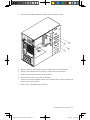
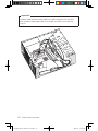
2. Disconnect the data and power cables from the hard disk drive.
3. Remove the four screws that secure the hard disk drive from drive bay.
4. Remove the hard disk drive by pulling it straight out of the drive bay.
5. Slide the new hard disk drive into the drive bay.
6. Screw back the four screws on the drive bay.
7. Connect the power and data cables to the hard disk drive. Refer to “Identifying
parts on the system board”.
8. Refer to the “Completing the installation”.
31039394_3000 H_HRG_EN_V2.0.indd17 17 2009.7.14 4:15:50 PM
Page is loading ...
Page is loading ...
Page is loading ...
Page is loading ...
Page is loading ...
Page is loading ...
Page is loading ...
Page is loading ...
Page is loading ...
-
 1
1
-
 2
2
-
 3
3
-
 4
4
-
 5
5
-
 6
6
-
 7
7
-
 8
8
-
 9
9
-
 10
10
-
 11
11
-
 12
12
-
 13
13
-
 14
14
-
 15
15
-
 16
16
-
 17
17
-
 18
18
-
 19
19
-
 20
20
-
 21
21
-
 22
22
-
 23
23
-
 24
24
-
 25
25
-
 26
26
-
 27
27
-
 28
28
-
 29
29


Lenovo 30221DU - H230 CORE2DUO 640G Wrless Desk Hardware Replacement Manual
- Type
- Hardware Replacement Manual
- This manual is also suitable for
Ask a question and I''ll find the answer in the document
Finding information in a document is now easier with AI
Related papers
-
Lenovo Essential C315 series Hardware Replacement Manual
-
-
-
Lenovo C225 Hardware Replacement Manual
-
Lenovo C300 Hardware Replacement Manual
-
-
Lenovo 7393 User manual
-
-
-