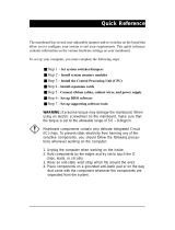
Page is loading ...

Mainboard User’s Manual
This publication, including all photographs, illustrations and
software, is protected under international copyright laws, with all
rights reserved. Neither this manual, nor any of the material
contained herein, may be reproduced without written consent of the
author.
The information in this document is subject to change without
notice. The manufacturer makes no representations or warranties
with respect to the contents hereof and specifically disclaims any
implied warranties of merchantability or fitness for any particular
purpose. Further, the manufacturer reserves the right to revise this
publication and to make changes from time to time in the content
hereof without obligation of the manufacturer to notify any person
of such revision or changes.
Trademarks
IBM, VGA, and PS/2 are registered trademarks of International
Business Machines.
Intel, Pentium/II/III, Pentium 4, Celeron and MMX are registered
trademarks of Intel Corporation.
Microsoft, MS-DOS and Windows 98/ME/NT/2000/XP are
registered trademarks of Microsoft Corporation.
PC-cillin is a registered trademark of Trend Micro Inc.
AMI is a registered trademark of American Megatrends Inc.
MediaRing Talk is a registered trademark of MediaRing Inc.
3Deep is a registered trademark of E-Color Inc.
Recovery Genius 21
st
, CD Ghost and Language Genius 21
st
are
trademarks of GoldenSoft Technology Co., Ltd.
SiS is a trademark of Silicon Integrated System Corporation.
Other names used in this publication may be trademarks and are
acknowledged.
Copyright © 2002
All Rights Reserved
MS9327E Series, V5.0
S650GL/April 2002

Mainboard User’s Manual
Notice:
Owing to Microsoft’s certifying schedule is various to every
supplier, we might have some drivers not certified yet by
Microsoft. Therefore, it might happen under Windows XP that a
dialogue box (shown as below) pop out warning you this
software has not passed Windows Logo testing to verify its
compatibility with Windows XP. Please rest assured that our RD
department has already tested and verified these drivers. Just
click the “Continue Anyway” button and go ahead the
installation.
II

Mainboard User’s Manual
Table of Contents
Trademarks.............................................................................. I
Chapter 1 .........................................................................................1
Introduction..................................................................................1
Key Features............................................................................2
Package Contents.....................................................................6
Static Electricity Precautions...................................................7
Pre-Installation Inspection.......................................................7
Chapter 2 .........................................................................................9
Mainboard Installation.................................................................9
Mainboard Components ........................................................10
I/O Ports.................................................................................11
Install A CPU ........................................................................12
Installing Memory Modules ..................................................13
Setting Jumper Switches........................................................14
Install the Mainboard.............................................................15
Install the Extension Brackets ...............................................17
VGA Extension Bracket .....................................................17
Optional Extension Brackets.................................................17
Install Other Devices.............................................................20
Expansion Slots.....................................................................22
Chapter 3 .......................................................................................23
BIOS Setup Utility.....................................................................23
Introduction ...........................................................................23
Running the Setup Utility......................................................24
Standard CMOS Setup Page..................................................25
Advanced Setup Page............................................................26
Power Management Setup Page............................................28
PCI / Plug and Play Setup Page.............................................29
Load Optimal Settings...........................................................30
Load Best Performance Settings............................................30
Features Setup Page...............................................................31
CPU PnP Setup Page.............................................................33
Hardware Monitor Page.........................................................34
Change Password...................................................................35
Exit ........................................................................................35
Chapter 4: Using the Mainboard Software....................................37
Utility Software Reference ........................................................38
III


1: Introduction
Chapter 1
Introduction
This mainboard has a Socket-478 processor socket for Intel
Pentium 4 type of processors supporting front side bus (FSB)
speeds up to 400 MHz.
This mainboard integrates the SiS650GL Northbridge along with
SiS961/962 Southbridge chipsets that support built-in AC97
Codec , 2 DDR + 2 SDR modules up to 2GB system memory, and
provides Ultra DMA 66/100/133 function. These chipsets’
function is detailed as the Chipset description in next section. This
mainboard integrates a 256-bit 3D/2D Graphics Engine, Video
Accelerator and Advanced Hardware Acceleration
MPEGI/MPEGII Video Decoder for the Intel Pentium 4 series
based PC systems. It has the external AGP slot with AGP 4X
266MHz capability and the built-in 10BaseT/100BaseTX
Network Interface. In addition, this mainboard has a full set of
I/O ports including two PS/2 ports for mouse and keyboard, two
serial ports, one parallel port, one MIDI/game port and six USB
ports -- two back-panel ports, onboard USB headers providing four
extra ports (they will support USB 2.0 if SiS962 SB installed on
the mainboard), and IEEE 1394 ports (if SiS 962 SB installed). By
means of the Extended USB Module connected to the mainboard,
you can make four extra USB ports.
This mainboard is ATX size and has power connectors for an ATX
power supply and measures 305 x 244mm.
1

Mainboard User’s Manual
Key Features
The key features of this mainboard include:
Socket-478 Processor
♦ The PGA Socket 478
♦ Supports Intel Pentium 4 series CPUs
♦ Supports up to 400 MHz Front-Side Bus
Chipset
There are SiS650GL Northbridge and SiS961/962 Southbridge
in this chipset in accordance with an innovative and scalable
architecture with proven reliability and performance. Here is a list
of the chipset arrangement and their respective features:
Northbridge Southbridge Function
SiS650GL SiS961 CPU FSB: 400MHz; Ultra DMA
ATA100; DDR266, without
AGP 4x slot
SiS650GL SiS962 CPU FSB: 400MHz; Ultra DMA
ATA133; DDR266, USB 2.0 and
IEEE1394 ports;
without AGP 4x slot
Memory Support
♦ Two 168-pin DIMM slots for SDRAM memory modules
♦ Two 184-pin DIMM slots for DDR memory modules
♦ Support SDRAM up to 133 MHz /DDR up to 266 MHz
memory bus
♦ Maximum installed memory is 2GB
Notice: You can NOT use SDRAM and DDR simultaneously.
Expansion Slots
♦ One ACR slot (Audio Communication Riser)
♦ Four 32-bit PCI slots for PCI 2.2-compliant bus interface
2

1: Introduction
Onboard IDE channels
♦ Primary and Secondary PCI IDE channels
♦ Support for PIO (programmable input/output) modes
♦ Support for Multiword DMA modes
♦ Support for Bus Mastering and Ultra DMA ATA
66/100/133 modes
Power Supply and Power Management
♦ ATX power supply connector
♦ Meets ACPI 1.0b and APM 1.2 requirements, keyboard
power on/off
♦ Supports RTC Alarm, Wake On Modem, AC97 Wake-Up
and USB Wake-Up
Onboard VGA
♦ Supports high performance & high quality 3D
Accelerator—A built-in 256-bit 3D engine, up to 143 MHz
3D engine clock speed
♦ Supports high performance 128-bit 2D Accelerator—Ultra-
AGPII
TM
2GB/s data read for all 2D engine functions
♦ Maximum Share Memory size is 64MB
AC97 Audio Codec: CMI9738
♦ Compliant with AC’97 2.2 specification
♦ Full-duplex Codec with independent and variable sampling
rate
♦ Earphone Buffer Built-In, SNR up to 90db
♦ 4Ch DAC, support 4-channel speak-out
♦ Advanced power management support
Built-in Ethernet LAN
♦ Built-in 10BaseT/100BaseTX Ethernet LAN
♦ SiS961 Embedded Fast Ethernet MAC and onboard Realtek
RTL8201 LAN PHY compliant with IEEE802.3u
100BASE-TX, 10BASE-T and ANSI X3.263 TP-PMD
standards
♦ Compliant with ACPI 1.0 and the Network Device Class
Power Management 1.0
3

Mainboard User’s Manual
♦ High Performance provided by 100Mbps clock generator
and data recovery circuit for 100Mbps receiver
Onboard I/O Ports
The mainboard has a full set of I/O ports and connectors:
♦ Two PS/2 ports for mouse and keyboard
♦ Two serial ports
♦ One parallel port
♦ One MIDI/game port
♦ Six USB ports (two backpanel ports, onboard USB headers
providing four extra ports)
♦ Audio jacks for microphone, line-in and line-out
Hardware Monitoring
♦ Built-in hardware monitoring for CPU & System
temperatures, fan speeds and mainboard voltages.
Onboard Flash ROM
♦ Supports Plug and Play configuration of peripheral devices
and expansion cards
USB 2.0 (for SiS962 SB only)
♦ Compliant with Universal Serial Bus Specification
Revision 2.0
♦ Compliant with Intel’s Enhanced Host Controller
Interface Specification Revision 0.95
♦ Compliant with Universal Host Controller Interface
Specification Revision 1.1
♦ PCI multi-function device consists of two UHCI Host
Controller cores for full-/low-speed signaling and one
EHCI Host Controller core for high-speed signaling
♦ Root hub consists 4 downstream facing ports with
integrated physical layer transceivers shared by UHCI and
EHCI Host Controller
♦ Support PCI-Bus Power Management Interface
Specification release 1.1
♦ Legacy support for all downstream facing ports
4

1: Introduction
IEEE 1394 (for SiS962 SB only)
♦ Fully supports provisions of IEEE1394-1995 for high-
performance serial bus and the P1394a draft 2.0 standard
♦ Provides three fully compliant cables ports at 100/200/400
Mbits/s and available with one, two or three ports
♦ Supports optional 1394 Annex J electrical isolation barrier
at PHY-link interface
♦ Supports power-down feature to conserve energy in battery
powered application
♦ Node power-class information signaling for system power
management
Bundled Software
♦ PC-Cillin2000 provides automatic virus protection under
Windows 98/ME/NT/2000/XP
♦ MediaRing Talk provides PC to PC or PC to Phone
internet phone communication
♦ Super Voice is data, fax and voice communication software.
♦ Recovery Genius 21
st
V5.0 provides the function to
recover, reserve and transfer hard disk data.
♦ CD Ghost is the software stimulating a real CD-ROM to
perform equivalent function.
♦ Language Genius 21
st
is the software to provide learning
tools of language and singing.
♦ PageABC is the software to help you create your own
home page.
Dimensions
♦ ATX form factor 305 x 244mm
5

Mainboard User’s Manual
Package Contents
Attention: This mainboard serial has three models, MS9327E,
MS9327E(USB) and MS9327E(IEE).
Please contact your local supplier for more information about
your purchased model. Each model supports different specification
listed as below:
Model Specification
MS9327E SiS650GL NB+SiS961 SB;
without AGP slot
MS9327E(USB) SiS650GL NB+SiS962 SB, support
USB2.0, without IEEE1394;
without AGP slot
MS9327E(IEE) SiS650GL NB+SiS962 SB, support
USB2.0 and IEEE1394;
without AGP slot
Your mainboard package contains the following items:
The mainboard
The User’s Manual
One diskette drive ribbon cable
One IDE drive ribbon cable
Software support CD
One VGA extension bracket
Optional Accessories
You can purchase the following optional accessories for this
mainboard.
Extended USB module
AMR v.90 56K Fax/Modem card
6

1: Introduction
Static Electricity Precautions
Components on this mainboard can be damaged by static
electricity. Take the following precautions when unpacking the
mainboard and installing it in a system.
1. Keep the mainboard and other components in their original
static-proof packaging until you are ready to install them.
2. During installation, wear a grounded wrist strap if possible. If
you don’t have a wrist strap, discharge static electricity by
touching the bare metal of the system chassis.
3. Handle the mainboard carefully by the edges. Avoid touching
the components unless it is absolutely necessary. During
installation put the mainboard on top of the static-protection
packaging it came in with the component side facing up.
Pre-Installation Inspection
1. Inspect the mainboard for damage to the components and
connectors on the board.
2. If you suspect that the mainboard has been damaged, do not
connect power to the system. Contact your mainboard vendor
and report the damage.
7

Mainboard User’s Manual
8

2: Mainboard Installation
Chapter 2
Mainboard Installation
To install this mainboard in a system, please follow the instructions
in this chapter:
Identify the mainboard components
Install a CPU
Install one or more system memory modules
Verify that all jumpers or switches are set correctly
Install the mainboard in a system chassis (case)
Connect any extension brackets or cables to connecting
headers on the mainboard
Install other devices and make the appropriate connections to
the mainboard connecting headers.
Note:
1. Before installing this mainboard, make sure jumper JP4 is
under Normal setting. See this chapter for information about
locating JP4 and the setting options.
2. Never connect power to the system during installation;
otherwise, it may damage the mainboard.
9

Mainboard User’s Manual
Mainboard Components
This diagram identifies major components on the mainboard.
Note: Any jumpers on your mainboard that do not appear in
the illustration above are for testing only.
10

2: Mainboard Installation
I/O Ports
The illustration below shows a side view of the built-in I/O ports
on the mainboard.
1. Upper PS/2 port connects a PS/2 pointing device.
2. Lower PS/2 port connects a PS/2 keyboard.
3. USB ports connect USB devices.
4. LPT1 connects printers or other parallel
communications devices.
5. COM ports connect serial devices such as mice or
fax/modems. COM1 is identified by the system as
COM1/3. COM2 is identified by the system as
COM2/4.
6. Game port connects a joystick or a MIDI device.
7. Three audio ports connect audio devices. The left
side jack is for a stereo line-out signal. The middle
jack is for a stereo line-in signal. The right side jack
is for a microphone.
8. LAN port connects to the network.
11

Mainboard User’s Manual
Install A CPU
This mainboard has a Socket-478 that supports Intel Pentium 4
series processors.
To ensure reliability, ensure that your processor has a
heatsink/cooling fan assembly.
Do neither try to install a Socket 370 processor nor a Socket 423 in
the Socket-478. A Socket 370 processor such as the Pentium III, or
Celeron, does not fit in the Socket 478.
The following processor is currently supported by this mainboard.
Intel P4 478: 1.4GHz ~ 2.2GHz, FSB: 400MHz
Installing a Socket-478 Processor
A processor installs into the ZIF (Zero Insertion Force) Socket-478
on the mainboard.
1. Locate the Socket-478 and CPUFAN. Pull the locking lever
out slightly from the socket and raise it to the upright position.
CPUFAN
Pin
-
1 Corner
Socket
-
478
2. On the processor, identify the Pin-1 corner by its beveled edge.
3. On the Socket-478, identify the Pin-1 corner. The Pin-1 corner
is at the top of the locking lever when it locked.
4. Match the Pin-1 corners and insert the processor into the
socket. No force is required and the processor should drop into
place freely.
12

2: Mainboard Installation
5. Swing the locking lever down and hook it under the catch on
the side of the socket. This secures the CPU in the socket.
6. All processors should be installed with a combination
heatsink/cooling fan, connect the cable from the fan to the
CPU fan power connector CPUFAN.
Installing Memory Modules
This mainboard accommodates 168-pin 3.3V/184-pin 2.5V
unbuffered SDRAM memory modules. The memory chips must be
standard or registered SDRAM (Synchronous Dynamic Random
Access Memory).
The CPU supports 100MHz system bus. The SDRAM DIMMs
and DDRs can synchronously work with 100 MHz or operates over
a 266 MHz system bus.
You must install at least one memory module in order to work out
the mainboard, either SDRAM or DDR SDRAM, but you can
not use them simultaneously.
DDR SDRAM provides 800 MB/s or 1 GB/s data transfer rate
corresponding with the bus 100 MHz or 266 MHz. It doubles the
rate to 1.0 GB/s and 2.1 GB/s by transferring data on both the
rising and falling edges of the clock. DDR SDRAM uses additional
power and ground lines and requires 184-pin 2.5V unbuffered
DIMM module rather than the 168-pin 3.3V unbuffered DIMMs
used by SDRAM.
DIMM3
DIMM4
DIMM1
DIMM2
13

Mainboard User’s Manual
Installation Procedure
The mainboard accommodates two memory modules. You must
install at least one module in any of the three slots. Each module
can be installed with up to 2GB system memory.
Refer to the following to install the memory modules.
1. Push the latches on each side of the DIMM slot
down.
2. Align the memory module with the slot. The
DIMM slots are keyed with notches and the
DIMMs are keyed with cutouts so that they can
only be installed correctly.
3.
Check that the cutouts on the DIMM module edge
connector match the notches in the DIMM slot.
4. Install the DIMM module into the slot and press it
firmly down until it seats correctly. The slot latches
are levered upwards and latch on to the edges of the
DIMM.
5. Install any remaining DIMM modules.
Setting Jumper Switches
Jumpers are sets of pins that can be connected together with
jumper caps. Jumper caps change the operating way of the
mainboard by changing the electronic circuits. If a jumper cap
connects two pins, these pins are SHORT; if it is removed, these
pins are OPEN.
1
JP4
14

2: Mainboard Installation
Jumper JP4: Clear CMOS Memory
This jumper can clear the contents of the CMOS memory. You
may need to clear the CMOS memory if the settings in the Setup
Utility are incorrect and prevent your mainboard from operating.
To clear the CMOS memory, disconnect all the power cables from
the mainboard and then move the jumper cap into the CLEAR
setting for a few seconds.
Function Jumper Setting
Clear CMOS Short Pins 1-2
Normal Mode Short Pins 2-3
Install the Mainboard
Install the mainboard in a system chassis (case). The board is an
ATX size mainboard with a twin-tier of I/O ports. You can install
this mainboard in an ATX case. Ensure that your case has an I/O
cover plate that matches the ports on this mainboard.
Install the mainboard in a case. Follow the instructions provided by
the case manufacturer using the hardware and internal mounting
points on the chassis.
1
ATXPW1
AUDO1
FP1
1
2
FAN2
Connect the power connector from the power supply to the
ATXPW1 connector on the mainboard.
If there is a cooling fan installed in the system chassis, connect the
cable from the cooling fan to the FAN2 fan power connector on the
mainboard.
15

Mainboard User’s Manual
Connect the case switches and indicator LEDs to the FP1 header.
Here is a list of the FP1 header’s pin assignments.
Pin Signal Pin Signal
1 SPEAKER 2 POWER LED
3 SPEAKER 4 POWER LED
5 SPEAKER 6 POWER LED
7 SPEAKER 8 KEYLOCK
9 KEY 10 KEYLOCK
11 KEY 12 KEY
13 KEY 14 KEY
15 HDD LED 16 HDD LED
17 RESET 18 RESET
19 SUSPEND LED 20 SUSPEND LED
21 POWER BUTTON 22 POWER BUTTON
If there are a headphone jack or/and a microphone jack on the front
panel, connect the cables to the AUDO1 header on the mainboard.
Here is a list of the AUDO1 header’s pin assignments.
Pin Signal Pin Signal
1 MIC 2 GND
3 MIC-P 4 VCC
5 FPOUT-R 6 RET-R
7 NC 8 KEY
9 FPOUT-L 10 RET-L
16
/