Page is loading ...

465 Controller for Fire Sprinkler Trace
Heating Systems
INSTALLATION, OPERATION AND
MAINTENANCE MANUAL

CONTENTS
Overview .............................................................................................. 3
1.1 Introduction ............................................................................................... 3
1.1.1 Trace Heating Systems for Fire Sprinkler Systems .... 3
1.2 Product Overview Description .................................................................. 4
1.2.1 Features ...................................................................... 4
1.3 Product Ratings ........................................................................................ 6
Installation and Wiring ....................................................................... 9
2.1 Introduction ............................................................................................... 9
2.2 Initial Inspection ........................................................................................ 9
2.3 Installation Location .................................................................................. 9
2.4 Mounting Procedures ............................................................................... 9
2.5 Wiring ..................................................................................................... 10
2.5.1 Power and Load Connections ................................... 10
2.5.2 Temperature Sensor and Extension Cables ............. 11
2.6 Supervisory Relay Connections ............................................................. 12
2.7 Initializing the Controller ......................................................................... 13
2.7.1 Initial Heating Cable Test .......................................... 13
465 Controller Operation ................................................................. 14
3.1 Quickstart ............................................................................................... 14
3.2 Settings Menu ........................................................................................ 16
3.3 System Menu.......................................................................................... 16
3.3.1 Info ............................................................................ 17
3.3.2 Test Program ............................................................. 17
3.3.3 Service ..................................................................... 17
3.3.4 Status ........................................................................ 17
3.3.5 Keylock Feature ........................................................ 18
3.3.6 Assign Device Number .............................................. 18
3.3.7 Reset ......................................................................... 18
3.4 Heating Cable and Pipe Menu ............................................................... 18
3.4.1. Sensor Setup ............................................................ 19
3.4.2 Control Mode ............................................................. 20
3.4.3 Setpoint ..................................................................... 20
3.4.4 Deadband .................................................................. 20
3.4.5 Minimum Expected Ambient Temperature ................ 20
3.4.6 Cable Type ................................................................ 20
3.4.7 Pipe Diameter ............................................................ 21
3.4.8 Low Temperature ...................................................... 21
3.4.9 High Temperature ..................................................... 21
3.4.10 High Limit Cutout Temperature, Setpoint ................ 21
3.4.11 Temperature Condition Filter .................................. 21
3.4.12 High Ground Fault Current ...................................... 21
3.4.13 Ground Fault Trip Level (HI GF Trip) ...................... 21

3.5 General Settings Menu ........................................................................... 22
3.5.1 Language .................................................................. 22
3.5.2 Country ...................................................................... 22
3.5.3 Date ........................................................................... 22
3.5.4 Time .......................................................................... 22
3.5.5. Voltage ..................................................................... 22
3.5.6 Select Unit of Measure .............................................. 22
3.5.7 Time Format .............................................................. 22
3.6 Supervisory Events ................................................................................ 23
3.6.1 Filter Times ................................................................ 23
3.6.2 Error Codes ............................................................... 23
Troubleshooting ............................................................................... 24
Appendix A: Proportional Ambient Sensing Control (PASC) ...... 26

nVent.com/RAYCHEM | 3
OVERVIEW
1.1 INTRODUCTION
This manual provides information pertaining to the installation, operation, testing and
maintenance of the nVent RAYCHEM 465 fire sprinkler heat trace controller. The
controller is c-UL-us listed for freeze protection of fire suppression system supply piping
and branch lines.
Additional copies of this user manual may be ordered separately through your nVent
Thermal Management representative or online at nVent.com.
This document covers the 465 controller and its available options. This fire sprinkler heat
trace controller is designed for the following trace heating products necessary to make up
the complete freeze protection system for supply piping and branch lines including
sprinkler heads: nVent RAYCHEM XL-Trace cables 5XL-1CR, 5XL-2CR, 5XL-1CT, 5XL-
2-CT, 8XL-1CR, 8XL-2CR, 8XL-1CT and 8XL-2-CT heating cables; as well as nVent
RAYCHEM RayClic-PC, RayClic-PS, RayClic-PT, RayClic-T, RayClic-S, RayClic-X,
RayClic-E, RayClic-LE, RayClic-SB-02, RayClic-SB-04 connection kits and accessories.
1.1.1 Trace Heating Systems for Fire Sprinkler Systems
The design and monitoring of trace heating systems for fire sprinkler systems shall be in
accordance with IEEE 515.1. Trace heating systems for fire sprinkler systems shall be
permanently connected to the power supply. If backup power is being provided for the
building electrical systems, it shall also provide backup power supply for the trace heating
system.
The thermal insulation used for the supply piping and branch lines shall be non-
combustible and protected with a sealed exterior non-combustible cover that will maintain
its integrity when exposed to water discharge as shown below:
Figure 1.1 – Example of sealed exterior non-combustible cover for the pipe insulation
The thermal insulation for the sprinklers shall be installed to comply with the obstruction
requirements of NFPA 13 so that the thermal insulation over the trace heating does not
unacceptably obstruct the sprinkler or cover the wrench boss.
When installing XL-Trace trace heating system on branch lines with sprinkler heads
follow the methods shown below:
Metal Cladding
Heat Tracing Cable
Pipe
Pipe Insulation

nVent.com/RAYCHEM | 4
Figure 1.2 – Installing XL-Trace on the sprinklers
Sprigs are typically 1 inch IPS with 0.5 inch thick thermal insulation. The insulation may
be oversized to accommodate the heating cable installation, resulting in no greater than 3
inch installed outer diameter (OD). Typically thermal insulation of 2 inch thickness should
be used on branch lines and supply piping to balance the heat loss of the system and
power output of the trace heating
For upright sprinklers only, the sprinkler heads shall be insulated up to the top of the
reducing bushing with a taper of 45° to avoid spray-pattern obstruction, as detailed in
Figure 14 of IEEE 515.1-2012.
The minimum sprinkler temperature rating shall be (155°F [68°C]).
1.2 PRODUCT OVERVIEW DESCRIPTION
The 465 controller monitors, controls, and communicates supervisory events and data for
one heating cable circuit.
The intended use of 465 controller is to control and monitor heat tracing circuits for fire
sprinkler systems. Each unit is a single point controller with a 5" inch color touch screen
display for intuitive set up and programming right out of the box. The 465 controller may
be used with line-sensing or ambient-sensing and proportional ambient-sensing control
(PASC) modes. It measures temperatures with two 2 KOhm / 77°F (25°C), 2-wire
Thermistor connected directly to the unit. The controller can also measure ground fault
current to ensure system integrity. If the equipment is used in a manner not specified by
nVent Thermal Management the protection provided by the equipment may be impaired.
1.2.1 Features
A detailed description of available features may be found in Section 4 of this manual.
Highlights of specific features are as follows:
Touchscreen Display
The touchscreen display provides the operator with large easy to read messages and
prompts, eliminating complex and cryptic programming.
Single or Dual Temperature Sensor Inputs
The ability to utilize one or two temperature sensor inputs allows the selection of ambient
or line sensing control modes and programming of all temperature parameters.

nVent.com/RAYCHEM | 5
High and Low Temperature
High and low temperature supervisory events are offered for both temperature sensor
inputs.
High Temperature Cutout
High temperature cutout is provided for both temperature sensor inputs.
Low Current Condition
The 465 controller offers a low current condition to identify situations where the heating
cable is not pulling adequate current.
Electromechanical Relay (EMR) Output
The 465 controller is equipped with a 24A rated electromechanical relay (EMR) output
switch with device failure supervisory status change.
Ground Fault Condition and Trip
Ground fault (GF) current levels are monitored and are displayed in milliamperes (mA).
The adjustable ground fault level gives the user the choice of ground fault current levels
suitable for the particular installation.
Proportional Ambient Sensing Control (PASC)
The 465 controller includes the Proportional Ambient Sensing Control (PASC) mode to
maximize the energy efficiency of the heat tracing system.
Temperature Sensor Failure
Both open and shorted sensors are detected by the controller.
Certification
nVent Thermal Management certifies that this product met its published specifications at
the time of shipment from the factory.
Limited Warranty
This nVent Thermal Management product is warranted against defects in material and
workmanship for a period of 18 months from the date of installation or 24 months from the
date of purchase, whichever occurs first. During the warranty period, nVent Thermal
Management will, at its option, either repair or replace products that prove to be
defective. For warranty service or repair, this product must be returned to a service facility
designated by nVent Thermal Management. The Buyer shall prepay shipping charges to
nVent Thermal Management and nVent Thermal Management shall pay shipping charges
to return the product to the Buyer. However, the Buyer shall pay all shipping charges,
duties, and taxes for products returned to nVent Thermal Management from another
country. nVent Thermal Management warrants that the software and firmware designated
by nVent Thermal Management for use with the 465 controller will execute its
programming instructions properly. nVent Thermal Management does not warrant that
the operation of the hardware, or software, or firmware will be uninterrupted or error-free.
Warranty Exclusion/Disclaimer
The foregoing warranty shall not apply to defects resulting from improper or inadequate
maintenance by the Buyer, Buyer-supplied software or interfacing, unauthorized
modification or misuse, operation outside of the specifications for the product, or improper
installation. No other warranty is expressed or implied. nVent Thermal Management
disclaims the implied warranties of merchantability and fitness for a particular purpose.
Exclusive Remedies
The remedies provided herein are the buyer’s sole and exclusive remedies. nVent
Thermal Management shall not be liable for any direct, indirect, special, incidental, or
consequential damages, whether based on contract, tort, or any other legal theory.
Conducted and Radiated Emissions: FCC Statement of Compliance
This equipment has been tested and found to comply with the limits for a Class B digital
device, pursuant to part 15 of the FCC Rules. These limits are designed to provide
reasonable protection against harmful interference in a commercial/ residential
installation. This equipment generates, uses and can radiate radio frequency energy and,
if not installed and used in accordance with the instructions, may cause harmful
interference to radio communications. However, there is no guarantee that interference
will not occur in a particular installation. If this equipment does cause harmful interference

nVent.com/RAYCHEM | 6
to radio or television reception, which can be determined by turning the equipment off and
on, the user is encouraged to try to correct the interference by one or more of the
following measures:
• Reorient or relocate the receiving antenna.
• Increase the separation between the equipment and receiver.
• Connect the equipment into an outlet on a circuit different from that to which the
receiver is connected.
• Consult the dealer or an experienced radio/TV technician for help.
CAUTION! Do not modify device. Any changes or modifications made to device that is
not expressly approved by nVent could void EMC compliance.
Innovation, Science and Economic Development (ISED) Canada
ICES-003 Compliance Label: CAN ICES-3 (B)/NMB-3(B)
1.3 PRODUCT RATINGS
General
Area of use
Nonhazardous locations
Approvals
UL Listed for fire sprinkler systems (VGNJ, VGNJ 7)
5XL1-CR, CT 8XL1-CR, CT
5XL2-CR, CT 8XL2-CR, CT
Supply voltage
120 V to 277 V, +/–10%, 50/60 Hz
Common supply for controller and heat
-tracing circuit
Enclosure
Protection
TYPE 12
Materials
Polycarbonate
Ambient operating temperature
range
32°F to 105°F (0°C to 40°C)
Ambient storage temperature
range
–4°F to 122°F (–20°C to 50°C)
Relative humidity
0% to 95%, noncondensing
Control
Relay type
Single pole single throw
Voltage, maximum
277 V nominal, 50/60 Hz
Switching current, maximum
24 A @ 105°F (40°C)
Control algorithms
EMR: Ambient On/off, proportional ambient sensing
control (PASC)
, Line sensing
Control range
32°F to 105°F (0°C to 40°C)
Monitoring
Temperature
Low range -40°F to 120°F (-40°C to 49°C) or OFF
High
range 32°F to 120°F (0°C to 49°C) or OFF
Ground fault
Supervisory range 20 mA to 200 mA
Trip range
20 mA to 200 mA

nVent.com/RAYCHEM | 7
Current
Low condition 0.25 A
Temperature Sensor Inputs
Quantity
Two inputs standard
Types
Thermistor 2KΩ/77°F (25°C), 2 Wire
10 ft (3 m) long, can be extended to 328 ft (100 m ) / 2 x
1
6 AWG
Sensor temperature range
-40°F (-40°C) to 194°F (90°C)
Sensor data
Temperature (°F)
Resistance (KΩ)
-40
32.34
-31
24.96
-22
19.48
-13
15.29
-4
12.11
5
9.655
14
7.763
23
6.277
32
5.114
41
4.188
50
6.454
59
2.862
68
2.387
86
1.684
104
1.211
122
0.8854
140
0.6587
158
0.4975
176
0.3807
Supervisory Output
Supervisory relay
Single pole double throw relay, volt-free, rating 1 A/24
VDC, 1 A/24
VAC
Programming and Setting
Method
Programmable touchscreen
Units
Imperial (°F, in.) or Metric (°C, mm)
Touchscreen display
Setpoint, status, sensor temperatures, supervisory
condition, s
ettings
Memory
Nonvolatile, restored after power loss
Stored parameters (measured)
Last event, maintain temperature, last event sensor
tem
peratures, control mode
Supervisory conditions
Low/high temperature, low current*

nVent.com/RAYCHEM | 8
Ground fault condition, trip*
Sensor
failure, or EMR failure
Loss of continutiy
Loss of in
coming supply voltage
Other
Password protection
Connection Terminals
Power supply input
Push-in Cage Clamp 18–10 AWG
Heating cable output
Push-in Cage Clamp 18–10 AWG
Ground
Push-in Cage Clamp 18–10 AWG
Sensors/supervisory relay
Push-in Cage Clamp 22–16 AWG
Mounting
Enclosure
Mounting DIN Rail 35 mm (Indoor only)
*Note: The 465 controller can't monitor the load current and ground fault current in each
cable segment when an external contactor is used. These supervisory conditions are
disabled when external contactor is used.

nVent.com/RAYCHEM | 9
INSTALLATION AND WIRING
2.1 INTRODUCTION
This section includes information regarding the initial inspection, preparation for use, and
storage instructions for the 465 controller.
Note: If the 465 controller is used in a manner not specified by nVent Thermal
Management, the protection provided by the controller may be impaired.
2.2 INITIAL INSPECTION
Inspect the shipping container for damage. If the shipping container or cushioning
material is damaged, it should be kept until the contents of the shipment have been
verified and the equipment has been checked mechanically and electrically. If the
shipment is incomplete, there is mechanical damage, a defect, or the controller does not
pass the electrical performance tests, notify the nearest nVent Thermal Management
representative. If the shipping container is damaged, or the cushioning material shows
signs of stress, notify the carrier as well as your nVent Thermal Management
representative. Keep the shipping materials for the carrier’s inspection.
Product Contents:
Tools Required:
2.3 INSTALLATION LOCATION
The 465 controller standalone version is approved for TYPE 12 protection class for
Indoor-use. Install the controller in an indoor, dry, clean, accessible location. Make sure
you install the controller within 328 ft (100 m) of where you want to monitor the pipe or
ambient temperature. The ambient temperature sensor shall be installed in the location
representative of the ambient temperature of the fire sprinkler system, including elevation.
Considerations should include accessibility for maintenance and testing and the location
of existing conduits.
2.4 MOUNTING PROCEDURES
The mounting steps are shown in Figure 2.1 A, B, C and D.
Drill conduit entry holes prior to mounting. Conduit entries should be made in the bottom of the
enclosure if possible to reduce the possibility of water entry from condensation or leakage.
Conduit entries must be drilled or punched using standard industry practices. Use bushings
1x

nVent.com/RAYCHEM | 10
suitable for the environment and install such that the completed installation remains
waterproof. Grounding hubs and conductors must be installed in accordance with Article 250
of the National Electrical Code and Part I of the Canadian Electrical Code. The hubs shall be
connected to the conduit before they are connected to the enclosure.
Figure 2.1 – Mounting procedures for the 465 controller
2.5 WIRING
The following drawings provide sample wiring diagrams for the 465 controller and optional
accessories. Grounding hubs and conductors must be installed in accordance with Article 250
of the National Electrical Code and Part I of the Canadian Electrical Code.
2.5.1 Power and Load Connections
The 465 controller may be powered directly from a 120 V to 277 V supply.
B
B
C
D
A

nVent.com/RAYCHEM | 11
All of the power terminals are labeled for easy identification. Do not attempt to use wire
sizes that exceed the marked terminal ratings and avoid terminating two wires on the
same terminal whenever possible.
Note: Follow the industry standard grounding practices. Do not rely on conduit
connections to provide a suitable ground. Grounding terminals/screws are provided for
connection of system ground leads. The glands/conduits should be inserted into the
metal grounding plate provided with the controller.
Power wires are connected to terminals labeled L (line), N (neutral) and PE (Ground).
Figure 2.2 – Power Connection
The heating cable conductors are connected to terminals labeled L/, N/ and the braid is
connected to PE.
Figure 2.3 – Heating Cable Connection
2.5.2 Temperature Sensor and Extension Cables
The 465 controller has two (2) temperature sensor inputs. Use only 2-wire Thermistor
2 KOhm / 77°F (25°C) sensors provided. Sensor 1 should be connected to terminals S1
and
┴
while Sensor 2 should be connected to terminals S2 and
┴
. The controller also
operates with just one sensor.
Note: The ambient temperature sensor shall be installed in the location
representative of the ambient temperature of the fire sprinkler system including
elevation.

nVent.com/RAYCHEM | 12
Figure 2.4 – Temperature Sensor Wiring
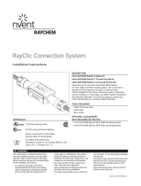
2.6 SUPERVISORY RELAY CONNECTIONS
The 465 controller includes terminals for one supervisory relay as shown in figure 2.5. It
can support both AC and DC power source (please refer to the max voltage and current
specifications for the relay above). It is a form C relay and may be wired for normally
open (N.O.) or normally closed (N.C.) operation.
The contractor shall connect the supervisory indicator to NO, COM to have the relay
signal a supervisory condition when it’s open. UL listed fire alarm control panel (FACP)
must be used with listed heat tracing system.
The supervisory relay is used to provide supervisory signal to a fire alarm system for any
of the following conditions:
1) Ground fault current
2) Low system temperature
3) High system temperature
4) Temperature sensor failure
5) Internal error
6) Loss of continuity
7) Loss of incoming supply voltage
Note: The supervisory relay is intended to be used for switching low-voltage, low-current
signals. Do not use this relay to directly switch line voltages.

nVent.com/RAYCHEM | 13
Figure 2.5 – Supervisory Relay Wiring
After all connections are made, connect the network cable from the touchscreen to the
port on the controller as shown below:
Figure 2.6 – Connect the touchscreen cable to the controller.
Close the lid with screwdriver and turn on the circuit breaker for the circuit. The circuit
breaker used for branch circuit protection should be maximum 30A circuit breaker. The
power wires used should be of appropriate size for the current rating as per NEC/CEC.
2.7 INITIALIZING THE CONTROLLER
2.7.1 Initial Heating Cable Test
To minimize the risk of damage to the controller due to a heating cable fault, the integrity
of the heating cable should be verified by performing the commissioning tests detailed in
the appropriate product installation and operating manual. These manuals can be found
on nVent.com.
These tests must be performed with the controller output disconnected. Once the cable
has been checked, it may be reconnected to the controller and power applied.
Supervisory Relay Terminals

nVent.com/RAYCHEM | 14
465 CONTROLLER OPERATION
3.1 QUICKSTART
When the unit is powered up for the first time, a Quickstart must be executed before the
unit is ready to start. The Quickstart helps to set all important settings, the unit will go in
main screen mode automatically when done. Quickstart is sufficient for normal
operations. More settings are available from the settings menu.
QUICKSTART MENU
Language
Select your language from the language menu.
Units
Select Imperial or Metric units
Connection
check
The unit is automatically executing a connection
check. It will check the heating cable connection,
ambient sensor and pipe sensor connection.
A connection of the unit to an external contactor
needs to be confirmed by the user.
WARNING: The 465 controller can't monitor
the load current and ground fault current in each
cable segment when an external contactor is
used. External ground fault protection must be
provided using appropriate GFEPD.
Country
Select a country in this menu.
Date
Use the up/down arrow keys to select the year,
month and day.
Time
Use the up/down arrow keys to set the hour and
minute.
Voltage
Select voltage.
Cable Type
Select heating cable used in the application.
Sensors Set-up
Setting up Sensors1 and 2 is fully flexible. Assign
each sensor to be a line or ambient sensor. Select
if you want the circuit to remain on if the given
sensor fails by clicking “Power On TS Fail”. Select
which sensor you would want to use for high limit
cutout. Make sure Sensor 1 is connected to
terminals S1 and
┴
.
Fine tune the individual sensor settings in the
parameters setting menu.
If only one sensor is used, leave the other sensor
settings blank.
Control Mode
This allows selection of the type of algorithm to be
used to maintain the setpoint temperature. Select
Ambient On/Off, PASC (Proportional Ambient
Sensing Control) or Line Sensing Control. If no
ambient or line sensor was assigned, the
corresponding control mode will be disabled.
Parameter
Settings
Setpoint
This is the temperature that the controller uses to
determine whether its output switch should be on
or off.
Range: 32ºF (0ºC) to 104ºF(40ºC)
Pipe Diameter
Select the appropriate pipe diameter from the
menu.
Low
Temperature
This allows the user to set the low temperature
setting for temperature sensor 1 and 2.
Range: -40ºF (-40ºC) to 120ºF (49ºC)
Default: 35°F (2°C)
High
Temperature
This allows the user to set the high temperature
setting for temperature sensor 1 and 2.
Range: 32ºF (0ºC) to 120ºF (49ºC)

nVent.com/RAYCHEM | 15
After QUICKSTART completion, the main menu screen will appear as follows:
Figure 3.1 – Main Menu Screen
1
Settings Button
2
Application Description
3
Firmware Version
4
Supervisory Event Indicator
5
Heat Cable Power Indicator (red when cable is powered)
6
Sensor 1 Measured Temperature
7
Sensor 2 Measured Temperature
8
Application Picture
9
Control Setpoint
10
Keylock Indicator
The Green LED will blink as follows:
• Normal operation, heater on: 1.5 sec on/0.5 sec off
• Normal operation, heater off: 1 sec on/ 1 sec off
• Supervisory condition: 0.2 sec on/1.8 sec off
Press the Settings button on the Main Menu Screen to get to the Settings Menu.
Default: 110°F (43°C)
Start Test
Program
The test program runs for 30 minutes, during
which all parameters will be ignored to check
heating cable and connection on site. You can
stop the test program at any time.
Key Lock
Key lock gets activated after the quick start
process. Please enter the passcode 3000 to
unlock the controller.
1
2
3
8
10
6
7
9
5
4

nVent.com/RAYCHEM | 16
3.2 SETTINGS MENU
Figure 3.2 – Settings Menu
The settings menu has three sections:
1. The System section allows you to read system information, run test program,
service the system such as upgrade the firmware, export event log/energy
consumption/temperatures or calibrate the screen, read status of the heat
tracing circuit, enable key lock, assign device ID and reset the system to
factory settings.
2. The Heating Cable and Pipe section allows you to set circuit parameters such
as control mode, set point, sensors, minimum ambient temperature,
temperature conditions and filters and ground fault settings.
3. The General settings enables you to select country, language, voltage, date,
time, and units.
The details of each section are provided on the next page.
3.3 SYSTEM MENU

nVent.com/RAYCHEM | 17
Figure 3.3 – System Menu
3.3.1 Info
3.3.2 Test Program
3.3.3 Service
3.3.4 Status
Purpose General info about the unit, name, commissioning date, firmware
version, nVent Thermal Management contact info per country.
Purpose The test program runs for 30 minutes, during which all parameters
will be ignored to check the heating cable and the connection on
site. You can stop the test program at any time.
Purpose
This is a password protected area for user to service the unit. The
default password is 2017.
Sub-menu includes:
Log File: Provides information about the warnings, last event,
control mode, heating cable, set point, ambient temperatures
measured and time stamp.
Calibrate Screen: Press the dot to calibrate the touch screen.
USB: USB drive can be used to upgrade the firmware, export
temperature, energy consumption, and event log data.
Energy Consumption: Displays the energy consumption chart over
time.
Select Power Adjustment: For Proportional Ambient Sensing
Control (PASC), Power Adjustment Factor can be selected. The
Range is from 10% to 200%. Default is 100%.
Purpose Displays the status and parameters for the heat tracing circuit.
Displays information such as sensor 1 and sensor 2 temperatures,
duty cycle, control mode, load current, GFP current and if the
external contactor is connected.

nVent.com/RAYCHEM | 18
3.3.5 Keylock Feature
3.3.6 Assign Device Number
3.3.7 Reset
3.4 HEATING CABLE AND PIPE MENU
Purpose
When key lock is “On”, the setup and timer menus are protected by
password. To unlock the unit, enter the predefined password
(3000). The unit will automatically lock itself after 10 minutes of
inactivity or when Lock “on” key is pressed.
Factory default: Key lock is “On”
Press the down arrow key to move to the next page of the System
Menu
Purpose Assign a 4 digit number to each device as an identifier for that
device.
Purpose To provide a quick method of resetting the controller’s configuration
parameters to the Factory Default parameters. Select “Yes” to
activate the Quick install menu and return all settings to factory
settings. Quick start process restarts automatically.

nVent.com/RAYCHEM | 19
Figure 3.4 – Heating Cable and Pipe Menu
In this menu, every parameter line shows the actual value/attribute for each parameter.
3.4.1. Sensor Setup
Sensor setup allows user full flexibility in configuring the temperature sensors as shown in
Figure 3.5 below:
Figure 3.5 – Sensor Setup
The 465 controller allows for two temperature sensors. Assign each sensor to be a line or
ambient sensor. If both the sensors are assigned as line or ambient sensors, the
controller will control based on the lower measured temperature of the two sensors.
Select if you want the circuit to remain on if the given sensor fails by clicking “Power On
TS Fail”. Select which sensor you would want to use for high limit cutout. Make sure
Sensor 1 is connected to terminals S1 and
┴
.
For Fire Sprinkler freeze protection application, both sensors are assigned as line sensors
with one sensor assigned as a high limit cutout sensor. The high limit cutout sensor
should be located where the fire sprinkler piping is expected to be the warmest. In the
case of sprinkler system with sprigs, the high limit cutout sensor should be located on one
of the sprigs.
At least one sensor needs to be connected for the controller to function. The second
sensor, if not connected, will be automatically disabled.
Note: The high limit cutout sensor should be located where the fire sprinkler piping is
expected to be the warmest.
/