Page is loading ...
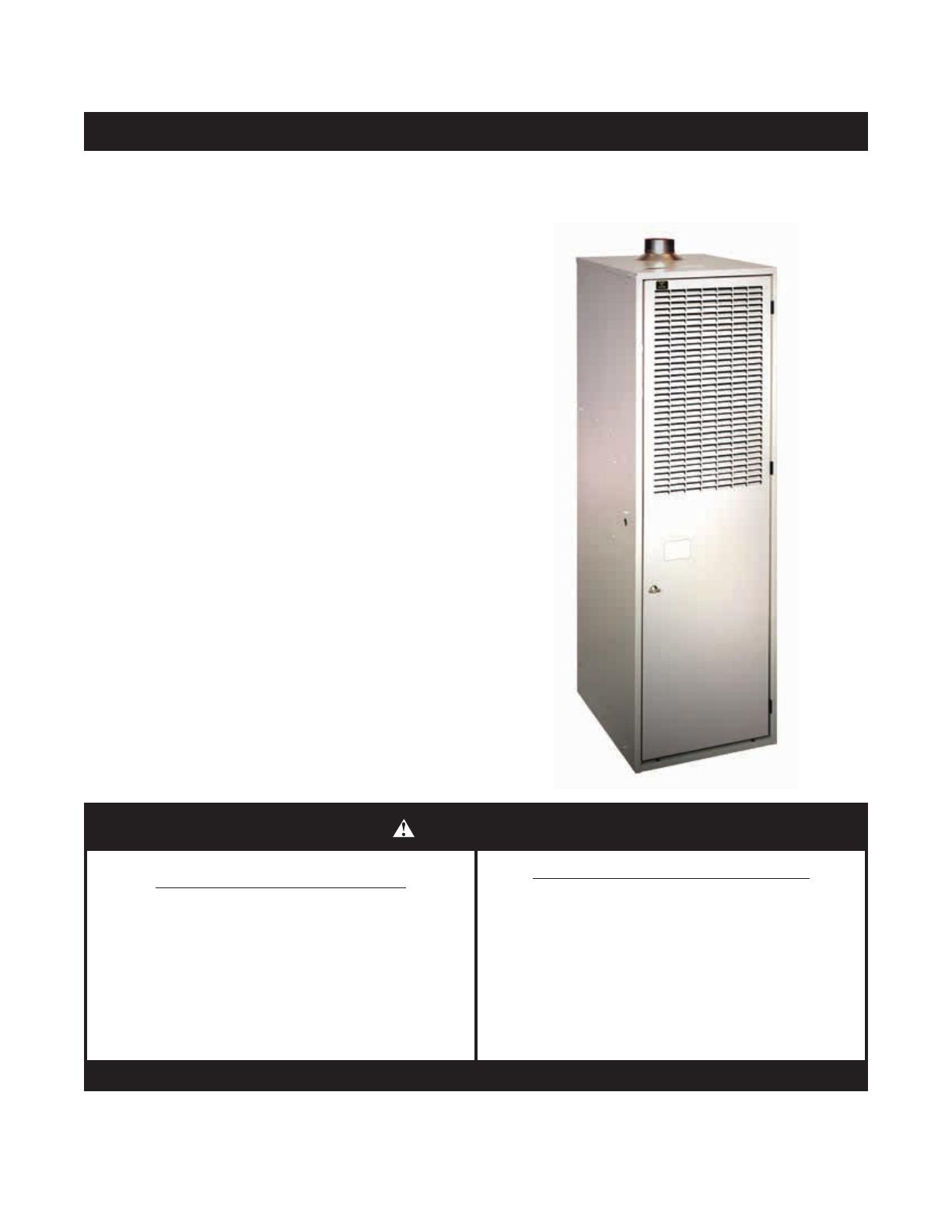
CMF3 70-PG Convertible (60, 70, & 75 KBTU/H Inputs)
CMF3 70-PO Convertible (60, & 70 KBTU/H Inputs)
Counterflow Gas or Oil Heating Appliance
INSTALLATION INSTRUCTIONS
For installation in:
• ManufacturedHomes
• Recreational Vehicles, Park Models, & Manufactured
Buildings
• ModularHomes/Buildings
WARNING
FIRE OR EXPLOSION HAZARD
• Failuretofollowsafetywarningsexactlycould
resultinseriousinjuryorpropertydamage.
•Installationandservicemustbeperformed
byaqualiedinstaller,serviceagencyorthe
gassupplier.
•Do not store or use gasoline or other
ammablevaporsandliquidsinthevicinity
ofthisoranyotherappliance.
WHAT TO DO IF YOU SMELL GAS
•Donottrytolightanyappliance.
•Do not touch any electrical switch; do not
useanyphoneinyourbuilding.
•Leavethebuildingimmediately.
•Immediately call your gas supplier from a
neighborsphone.Followthegassuppliers
instructions.
•Ifyoucannotreachyourgassupplier,call
theredepartment.
DONOTDESTROY.PLEASEREADCAREFULLY&KEEPINASAFEPLACEFORFUTUREREFERENCE.

2
TABLE OF CONTENTS
IMPORTANT SAFETY INFORMATION..........................3
REQUIREMENTS & CODES..........................................3
GeneralInformation......................................................4
OperationofFurnaceDuringConstruction...................4
MinimumInstallationClearances..................................5
GeneralInformation......................................................6
CombustionAirQuality.................................................6
DirectVentFurnaces....................................................6
VentilaireIIIorIV(AccessoryItem)..............................7
CIRCULATING AIR REQUIREMENTS...........................7
Plenums&AirDucts.....................................................7
UnconditionedSpaces..................................................8
ClosetInstallations.......................................................8
FURNACE INSTALLATION............................................8
GeneralInformation......................................................8
BeforeYouInstallthisFurnace....................................8
LocatingtheUnit...........................................................9
MA-200BaseInstallation..............................................9
InstallingtheFurnaceonanMA-200Base..................10
MA-100UniversalBaseInstallation..............................10
InstallingtheFurnaceonanMA-100Base..................10
CombustionAirDuct/PipeInstallation..........................10
SRJRoofJackInstallation............................................11
DamperInstallation.......................................................11
Oilpiping-POSeriesOnly...........................................14
ELECTRICAL CONNECTIONS......................................15
Pre-ElectricalChecklist.................................................15
LineVoltage..................................................................16
WiringConnections......................................................16
Grounding.....................................................................16
ThermostatConnections..............................................16
BlowerSpeed...............................................................16
START-UP & ADJUSTMENTS.......................................17
Pre-StartCheckList.....................................................17
OperatingInstructionsforPGDirectIgnitionBurner....18
OperatingInstructionsforPOOILBurners...................19
FiringRateConversion.................................................19
OPERATING SEQUENCE..............................................20
PGGasFurnaces.........................................................20
POOilFurnaces...........................................................20
TROUBLESHOOTING....................................................21
PGDirectIgnition-GasGun(PowerBurner)................21
POOilFurnace.............................................................22
ControlModuleStatusIndicator...................................22
UNIT MAINTENANCE.....................................................23
FurnaceFilter...............................................................23
BlowerCompartment....................................................23
CombustionAirandVentingSystem............................23
COMPONENT FUNCTIONS...........................................23
FIGURES & TABLES......................................................24
WIRING DIAGRAM.........................................................25
FURNACE COMPONENTS............................................26
INSTALLATION CHECKLIST.........................................28
3
IMPORTANT SAFETY INFORMATION
INSTALLER:Pleaseread allinstructionsbefore servicing
this equipment. Pay attention to all safety warnings and
anyotherspecial noteshighlightedinthe manual.Safety
markings are used frequently throughout this manual to
designateadegreeorlevelofseriousnessandshouldnot
be ignored. WARNING indicates a potentially hazardous
situationthatifnotavoided,couldresultinpersonalinjuryor
death.CAUTIONindicatesapotentiallyhazardoussituation
thatifnotavoided,mayresultinminorormoderateinjuryor
propertydamage.
WARNING:
ELECTRICAL SHOCK, FIRE
OR EXPLOSION HAZARD
Failuretofollowsafetywarningsexactlycould
resultinseriousinjuryorpropertydamage.
Improper servicing could result in dangerous
operation, serious injury, death or property
damage.
•Before servicing, disconnect all electrical
powertoairhandler.
•Whenservicingcontrols,labelallwiresprior
todisconnecting.Reconnectwirescorrectly.
•Verifyproperoperationafterservicing.
WARNING:
Do not use this appliance if any part has been
submergedunderwater.Immediatelycallaqualied
service technician to inspect the appliance and
toreplaceanypartofthecontrolsystemandany
gascontrolthathasbeensubmergedunderwater.
REQUIREMENTS & CODES
WARNING:
This unit must be installed in accordance with
instructions outlined in this manual during the
installation, service, and operation of this unit.
Unqualied individuals should not attempt to
interprettheseinstructionsorinstallthisequipment.
Failure to follow safety recommendations could
resultinpossibledamagetotheequipment,serious
personalinjuryordeath.
• Furnace must be installed in accordance with these
instructions, all applicable local building codes and the
current revision of the National Fuel Gas Code (ANSI
Z223.1/NFPA54),InstallationofOilBurningEquipment
(ANSI/ NFPA31) or the National Electric Code (ANSI/
NFPA70),theManufacturedHomeConstruction&Safety
Standard,Title24CFR,Part3280,orwhenthisstandard
isnotapplicable, the Standard for Manufactured Home
InstallationManufacturedHomeSites,Communitiesand
Setups(ANSI225.1).
• Useonlywithtypeofgasoroilapprovedforthisfurnace.
Refertothefurnaceratingplate.
• Install this furnace only in a location and position as
speciedonpage5.
• Provide adequate combustion and ventilation air to the
furnacespaceasspeciedonpage5andpage6.
• Provideadequateclearancesaroundtheventairintake
terminalasspeciedinTable1(page8).
• Combustion products must be discharged outdoors.
Connectthisfurnacetoan approved vent system only,
asspeciedonpage5andpage6.
• Never test for gas leaks with an open ame. Use
a commercially available soap solution to check all
connections.Seepages13.
• This furnace is designed to operate with a maximum
external pressure rise of 0.3 inches of water column.
Consult Table 4 (page 17), and the rating plate for the
proper circulating air ow and temperature rise. It is
important that the duct system be designed to provide
the correct ow rates and external pressure rise. An
improperlydesignedductsystemcanresultinnuisance
shutdowns,andcomfortornoiseissues.
• Thisfurnacemaynotbeused for temporary heatingof
buildingsorstructuresunderconstruction.
• The Commonwealth of Massachusetts requires
compliancewithregulation248CMR 4.00 and 5.00 for
installationofthrough–the–wallventedgasappliances
asfollows:
1. For direct-vent appliances, mechanical-vent heating
appliancesordomestichotwaterequipment,wherethe
bottomoftheventterminalandtheairintakeisinstalled
belowfourfeetabovegradethefollowingrequirements
mustbesatised:
a.) Acarbonmonoxide(CO)detectorandalarmshallbe
placedoneachoorlevelwheretherearebedrooms.
The detector shall comply with NFPA 720 (2005
Edition) and be mounted in the living area outside
thebedroom(s).
b.) A (CO) detector shall be located in the room that
housestheapplianceorequipmentandshall:
•Be powered by the same electrical circuit as the
applianceorequipment.Onlyoneserviceswitchshall
powertheapplianceandthe(CO)detector;

4
•Havebatteryback-uppower;
•Meet ANSI/UL 2034 Standards and comply with
NFPA 720 (2005 Edition); and Approved and listed
by a Nationally Recognized Testing Laboratory as
recognizedunder527CMR.
c.) A Product-approved vent terminal must be used,
andifapplicable,aproduct-approvedairintakemust
be used. Installation shall be in strict compliance
with the manufacturer’s instructions. A copy of the
installationinstructionsshallremainwiththeappliance
orequipmentatthecompletionoftheinstallation.
d.) Ametalorplasticidenticationplateshallbemounted
attheexteriorofthebuilding,fourfeetdirectlyabove
the location of vent terminal. The plate shall be of
sufcientsize,easilyreadfrom a distance ofeight
feetaway,andread“GasVentDirectlyBelow”.
2. For direct-vent appliances, mechanical-vent heating
appliancesordomestichotwaterequipmentwherethe
bottomoftheventterminalandtheairintakeisinstalled
abovefourfeetabovegradethefollowingrequirements
mustbesatised:
a.) A(CO)detectorandalarmshallbeplacedoneach
oorlevelwheretherearebedrooms.Thedetector
shallcomplywithNFPA720(2005Edition)andbe
mountedinthelivingareaoutsidethebedroom(s).
b.) The(CO)detectorshall:
•Belocatedintheroomthathousestheapplianceor
equipment;
•Behard-wiredorbatterypoweredorboth.
•ShallcomplywithNFPA720(2005Edition).
c.) A product-approved vent terminal must be used,
andifapplicable,aproduct-approvedairintakemust
be used. Installation shall be in strict compliance
with the manufacturer’s instructions. A copy of the
installationinstructionsshallremainwiththeappliance
orequipmentatthecompletionoftheinstallation.
GeneralInformation
Theinformationlistedbelowisforreferencepurposesonly
anddoesnotnecessarilyhavejurisdictionoverlocalorstate
codes.Alwaysconsultwithlocalauthoritiesbeforeinstalling
anygasappliance.
DuctSystems
• USandCANADA:AirConditioningContractorsAssociation
(ACCA) Manual D, Sheet Metal and Air Conditioning
Contractors National Association (SMACNA), or American
Society of Heating, Refrigeration, and Air Conditioning
Engineers(ASHRAE)FundamentalsHandbook
Electrical Connections
• US:NationalElectricalCode(NEC)ANSI/NFPA70
• CANADA:CanadianElectricalCodeCSAC22.1
Gas Piping & Gas Pipe Pressure Testing
• US:NFGCandNationalPlumbingCodes
• CANADA:NSCNGPIC
General Installation
• US: Current edition of the NFGC and the NFPA 90B. For
copies,contacttheNationalFireProtectionAssociationInc.,
Batterymarch Park, Quincy, MA 02269; or American Gas
Association,400N.Capitol,N.W.,WashingtonDC20001or
www.NFPA.org
• CANADA:NSCNGPIC.Foracopy,contactStandardSales,
CSA International, 178 Rexdale Boulevard, Etobicoke
(Toronto),Ontario,M9W1R3Canada
Safety
• US:(NFGC)NFPA54–1999/ANSIZ223.1andtheInstallation
Standards,WarmAirHeatingandAirConditioningSystems
ANSI/NFPA90B.
• CANADA:CAN/CSA-B149.1and.2–M00NationalStandard
ofCanada.(NSCNGPIC)
OperationofFurnaceDuringConstruction
CAUTION:
Operatinggasfurnacesinconstructionenvironments
cancauseavarietyofproblemswithinthefurnace
and may significantly reduce the life or the
performanceofthefurnace.Thereforeoperating
thefurnaceduringconstructionisnotpermitted
andwillvoidthewarranty.

5
COMBUSTIONAIR&VENTING
REQUIREMENTS
WARNING:
CARBON MONOXIDE POISONING HAZARD
Failuretofollowthestepsoutlinedbelowfor
eachapplianceconnectedtotheventingsystem
being placed into operation could result in
carbonmonoxidepoisoningordeath.
Thefollowingstepsshallbefollowedwitheach
individualapplianceconnectedtotheventing
systembeingplacedinoperation,whileallother
appliancesconnectedtotheventingsystemare
not in operation:
1.Seal any unused openings in the venting
system.
2.Inspecttheventingsystemforpropersizeand
horizontalpitch,asrequiredintheNationalFuel
GasCode,ANSIZ223.1/NFPA54ortheCSA
B149.1,NaturalGasandPropaneInstallation
Codesandtheseinstructions.Determinethat
there is no blockage or restriction, leakage,
corrosionandotherdeciencieswhichcould
causeanunsafecondition.
3.Asfaraspractical,closeallbuildingdoors
andwindowsandalldoorsbetweenthespace
in which the appliance(s) connected to the
ventingsystemarelocatedandotherspaces
ofthebuilding.
4.Closereplacedampers.
5.Turn on clothes dryers and any appliance
notconnectedtotheventingsystem.Turnon
anyexhaust fans, suchas range hoodsand
bathroomexhausts,sotheyareoperatingat
maximum speed. Do not operate a summer
exhaustfan.
6.Follow the lighting instructions. Place the
appliance being inspected into operation.
Adjustthethermostatsoapplianceisoperating
continuously.
7.Test for spillage from draft hood equipped
appliances at the draft hood relief opening
after5minutesofmainburneroperation.Use
theameofamatchorcandle.
8.Ifimproperventingisobservedduringanyof
theabovetests,theventingsystemmustbe
correctedinaccordancewiththeNationalFuel
GasCode,ANSIZ223.1/NFPA54and/orCSA
B149.1,NaturalGasandPropaneInstallation
Codes.
9.After it has been determined that each
appliance connected to the venting system
properlyventswhentestedasoutlinedabove,
returndoors,windows,exhaustfans,replace
dampers and any other gas-red burning
appliancetotheirpreviousconditionsofuse.
Table1.MinimumClearanceRequirements
INSTALLATION CLEARANCES
CLOSET ALCOVE
Front* 6" 18"
Rear 0" 0"
Sides 0" 0"
Top 17" 17"
Ductw/in3ftoffurnace 1/4" 1/4"
Vent 6” 6”
Plenum 1" 1"
RoofJackBarrel 0” 0”
LEFT
SIDE
FRONT
RIGHT
SIDE
REAR
VENT
†
NOTES:
* ServiceClearance
AlcoveInstallations-Allow18in.minimumclearancefromfrontof
unittonearestwallorpartitionforservicing.
Closetinstallations-Requireareturnairgrillinstalledinthedooror
apartiallylouvereddooracrosstheopeningforproperaircirculation.
For clearances 6” or greater, the closet must have an open free
areaof235in
2
minimum.Forspecialclearancesbetween1”-5”,
requirementsarealouvereddoorwithaminimumof250in
2
(1613
cm
2
)freearea.Afullylouveredclosetdoorisstronglyrecommended
forbothinstallationtypes.
MinimumInstallationClearances
• Access for positioning and servicing the unit must be
considered when locating unit. The need to provide
clearance for access to panels or doors may require
clearancedistancesoverandabovetherequirements.
• This appliance must be installed in accordance with
clearances listed in Table 1. The furnace must be
installedwithampleclearanceforeasyaccesstotheair
lter, blower assembly, burner assembly, controls, and
ventconnections.
• Locate and install this unit in position as specied on
page 8 & page 9. This unit is designed only for Indoor
installationsandshouldbelocatedwithconsiderationof
minimizingthelengthofthesupplyandreturnducts.
• Sufcient clearance for unobstructed airow through a
louvered door must be maintained in order to achieve
ratedperformance.Airreturnto the furnace must have
the minimum required total free area of 200 in
2
(1290
cm
2
)Mayalsoincludereturnairgrilleandframeassembly
(P/N902989)orwallmountgrille(P/N902999).

6
GeneralInformation
WARNING:
This furnace must be installed by a qualied
installingagencyandinaccordancewithapplicable
localcodesandordinancesthatgovernthistypeof
equipment.Failuretoproperlyinstallthefurnace,
baseassembly,andventingsystemasdescribed
hereinmaydamagetheequipmentand/orthehome,
cancreateareorasphyxiationhazard,violates
U.S.listingrequirements,andwillvoidthewarranty.
ThisfurnaceisNOTapprovedforinstallationwith
split system air conditioning. Use a NORDYNE
packagedairconditioningsystem.
• Instructionsfordeterminingtheadequacyofcombustion
airforaninstallationcanbefoundinthecurrentrevisionof
theNFGC(ANSIZ223.1/NFPA54).Theserequirements
areforUSinstallationsasfoundintheNFGC.Consult
localcodesforspecialrequirements.
• The requirements in Canada (B149.1) are structured
differently. Consult with B149.1 and local code ofcials
forCanadianinstallations.
The CMF3 Series furnace can draw combustion air from
outside the home (direct vent) or from the space being
conditioned.Thishighquality,directventfurnaceisusedfor
manufacturedhousingapplications.ItiscertiedtotheUL307
standards(UL307-Aforoilmodels;UL307-Bforgasmodels).
TheCMF3furnaceisavailableinpowergas(PGmodels)
orpoweroil(POmodels)andcanbeconvertedfrompower
oil to power gas, and vice versa. The power gas models
aredesignedfor operation with either natural or propane
(LP) gas. The ring rate of the CMF3 Convertible Series
canbeeld-installed(usingacertiedconversionkit)bya
qualiedservicetechnician.Refertopage14forconversion
information.
CAUTION:
Exhaustfans,clothesdryers,replacesandother
appliances that force air from the house to the
outdoors can create a negative pressure inside
thehouse,resultinginimproperfurnaceoperation
orunsafeconditionssuchasamerollout.Itis
imperative that sufcient air exchange with the
outdoorsisprovidedtopreventdepressurization.
Additional information about how to test for
negativepressureproblemscanbefoundinthe
NFGC.
CombustionAirQuality
CAUTION:
Combustionairmustnotbedrawnfromacorrosive
atmosphere.
Provisionsforadequatecombustionairandventilationair
must be in accordance with the ANSI Z223.1/NFPA 54,
(NationalFuelGasCode),ANSI/NFPA31(InstallationofOil
BurningEquipment),andallapplicablelocalcodes.
The installation of the furnace must allow for adequate
supplyoffreshairforcombustion.Airopeningsontopofthe
furnaceandopeningsinclosetdoorsorwallsmustnever
be restricted. The combustion air opening of the furnace
mustbedesignedandlocatedtopreventblockagebysnow.
Ifthefurnaceisoperatedwithoutadequateairforcombustion,
theameroll-outswitchwillopenandshutoffthegassupply
totheburners.
IMPORTANT NOTE
Thissafetydeviceisamanuallyresetswitch.DONOT
install jumper wires across these switches to defeat
their function or reset a switch without identifying
andcorrectingthefaultcondition.Ifaswitchmustbe
replaced,useonlythecorrectsizedpartspeciedinthe
ReplacementPartsListprovidedonline.
Thecombustionairfromtheoutsideneedstobeclearof
chemicals that can cause corrosion. Excessive exposure
to contaminated combustion air will result in safety and
performancerelatedproblems.Thelistbelowareexamples
ofchemicalcontaminantsfoundinawidevarietyofsome
commoncommercialandhouseholdproducts:
Permanentwavesolutions
Chlorinatedwaxesandcleaners
Chlorinebasedswimmingpoolchemicals
Watersofteningchemicals
De-icingsaltsorchemicals
CarbonTetrachloride
Cleaningsolvents(perchloroethylene)
Printinginks,paintremovers,varnishes,etc.
HydrochloricAcid
Cementsandglues
Antistaticfabricsofteners
Masonryacidwashingmaterials
Whendrawingcombustionairfromunderneaththehome,a
ventorductofatleast18in
2
offreeareashouldbeinstalled
outside and completely unobstructed. When using the
combustionairduct,makesureitextendsthroughtheoor.
DirectVentFurnaces
Direct Vent furnaces draw combustion air directly from
theoutdoorsandthenventthecombustionproductsback
outside,isolatingtheentiresystemfromtheindoorspace.
Itisimportanttomakesurethatthewholesystemissealed
andclearancestocombustiblesaremaintainedregardless
oftheinstallationbeinginaconnedorunconnedspace.
Thecombustionairhoseisprovidedandmustbeusedfor
directventapplications.
OnlyforspecialCB-200Acottagebaseinstallationscanthe
CMF3furnacedrawscombustionairfromtheconditioned
space. The CB-200A cottage base is an accessory item
thatcanbepurchasedseparately.Refertothereplacement
partslistingprovidedwiththefurnacetoorderthecottage
basekit.Followthe instructionsprovidedwiththe kitsfor
properinstallation.
When unsure about combustion air supply availability, a
directventsystemshouldbeused.Forsmallrooms,conned
spaces,tightconstructionorsimilarsituationsinwhichthe
combustion air requirements of the furnace might not be
met,adirectventsystemmustbeused.
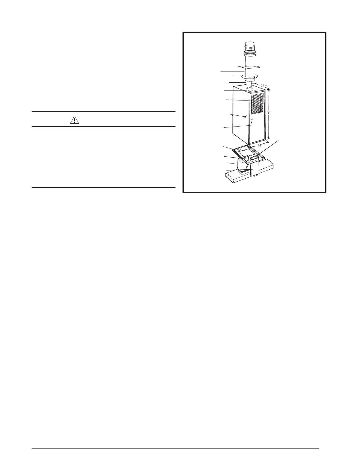
Forallmanufacturedhousingapplications,theCMF3furnace
mustbeventedusingtheSRJseriesroofjackasshownin
Figure1.Theinstructionsforselectingtheproperroofjack
foryourinstallationaredetailedlaterintheseinstructions.

7
VentilaireIIIorIV(AccessoryItem)
CAUTION:
MAINTAIN 2 1/2” MINIMUM CLEARANCE BETWEEN
FLUE PIPE AND FLEX DUCT. FAILURE TO
COMPLY WITH THIS RESTRICTION COULD
CAUSE EQUIPMENT DAMAGE. VENTILAIRE III
ILLUSTRATED OTHER LISTED VARIATIONS
AVAILABLE.CHECKWITHMANUFACTURER.
The Ventilaire air quality packages are available to meet
theventilationrequirementsasoutlinedinH.U.D.Standard
Part3280.103 (b)(2).Thesepackagesintroduceoutdoor
air into the living space during furnace blower operation.
TheVentilAireIValsoservestoexhaustmoistand/orhot
airfromtheatticspace.SeeFigure2fortypicalinstallation.
Completeinstallationinstructionsaresuppliedwitheachair
qualitypackage.
VENT PIPE
3 FEET
MIN.
ROOF JACK
ASSEMBLY
ROOF CAP
ASSEMBLY
FLEX
DUCT
CEILING TRIM
COLLAR
CONNECTOR
DRAW BAND
FURNACE
DRAW
BAND
57”
Figure1.TypicalInstallation
VentilAireIII
VentilAireIV
Figure2.VentilAireIII&IV
CIRCULATING AIR REQUIREMENTS
WARNING:
Allsupplyductsmustbesecuredtothefurnace
with sheet metal screws and adequately sealed.
Whensupplyairisprovidedthroughthebottom
oftheunit,thejointbetweenthefurnaceandthe
plenummustbeairtight.
Thesurfacethatthefurnaceismountedonmust
providesoundphysicalsupportofthefurnacewith
nogaps,cracksorsaggingbetweenthefurnace
andtheoororplatform.
Supply air ducts must not be connected to any
otherheat producingdevice such as a replace
insert,stove,etc.Thismayresultinre,explosion,
carbon monoxide poisoning, personal injury, or
propertydamage.
Plenums&AirDucts
Thisunitisdesignedonlyforusewithabottomsupplyduct
andmustbeinstalledinaccordancewiththestandardsofthe
NationalFireProtectionAssociationStandardforInstallation
of Air Conditioning Systems (NFPA 90A), Standard for
InstallationofResidenceTypeWarmAirHeating and Air
ConditioningSystems(NFPA90B),andallapplicablelocal
codes.NFPApublicationsareavailablebywritingto:National
FireProtectionAssociation,BatterymarchPark,Quincy,ME
02269orvisitwww.NFPA.orgontheinternet.
• Designtheairductsaccordingtomethodsdescribedby
theAirConditioningContractorsofAmerica(ACCA).
• Airductsmustbealuminum,tinplate,galvanizedsheet
steel, or other approved materials for outlet air ducts.
Snap-Lock or Pittsburgh-Lock seams are preferred. All
other types of seams must be made tight to prevent
leakage.
• It is good practice to seal all connections and joints
with industrial grade sealing tape or liquid sealant.
Requirements for sealing ducts vary from region to
region.Consultwithlocalcodesforrequirementsspecic
toyourarea.
• Gaspipingmustnotruninorthroughanyoftheairduct
system.
SupplyAirConnections
• The supply duct system must be designed so that the
static pressure measured external to the furnace does
not exceed the listed static pressure shown on the
furnace rating plate. The supply air must be delivered
to the heated space by duct(s) secured to the furnace
casing,runningfulllengthandwithoutinterruption.
• Ductsystemmustbedesignedsothatnosupplyregisters
arelocatedinductsystemdirectlybelowthefurnace.
Dampers
Anautomatedshutoffdamperisrequiredwhenthehomeis
airconditionedbyaself-containedunit.Adamperisrequired
to prevent chilled air from owing over the furnace heat
exchanger.Thisdamperisdesignedtotinthefeederduct
cavity,directlyunderthefurnace.Forproperinstallation,refer
totheinstructionsprovidedwiththedamper.SeeTechnical
SalesLiteratureonline.

8
UnconditionedSpaces
All duct work passing through unconditioned space must
beproperlyinsulatedtominimizeductlossesandprevent
condensation. Use insulation with an outer vapor barrier.
Refertolocalcodesforinsulationmaterialrequirements
Closet Installations
WARNING:
Failuretocomplywiththethefollowinginstructions
mayresultinre,asphyxiationorcarbonmonoxide
poisoning.
Forproperaircirculation,closetinstallationsrequireareturn
airgrillinstalledinthedoororsidewallthatexchangeswith
thelivingareaofthehomeasshowninFigure3.Apartially
louvereddoormayalsobeusedacrosstheopening.Return
air openings should not be located to draw air directly
fromabathroom.Grillesplacedinasidewallrequirea6”
clearancefromthewalltothefurnacesothattheairmay
enterthefrontgrilleofthefurnace.Inaddition,allreturnair
systems,includingtheoorandceilingsystems,mustmeet
thefollowingconditions:
• The return air opening, regardless of its location in the
closet, must not be smaller than size specied on unit
data label. If located in the oor, the opening must be
provided with a means of preventing its inadvertent
closurebyatobject(s)placedovertheopening.
• The return-air opening into the closet, regardless of its
location,musthaveanopenfreeareaof200in
2
(1290
cm
2
)minimum.
• The cross-sectional area of the return duct system (in
oororceiling)leadingintotheclosetmustnotbeless
than200in
2
(1290cm
2
).
• The total free area of the openings in the oor or the
ceilingregistersservingthereturnairductsystemmust
notbenotlessthan300in
2
(1935cm
2
).
• Materialslocatedinthereturnductsystemshallhavea
amespreadclassicationof200orless.
• Noncombustiblepanshavingoneinchupturnedanges
are located beneath openings in a oor return duct
system.
• Hollowspacesusedasductsorplenumsforenvironmental
airmaycontainmineral-insulatedmetalsheathedcable,
aluminumsheathedcable,electricalmetallictubing,rigid
metalconduit,exiblemetalconduit(nottoexceed4ft),
ormetal-cladcables.Wiringmaterials,xtures,aretobe
suitablefortheexpectedambienttemperaturestowhich
theywillbesubjected.
• Thenegativepressureintheclosetmustnotbelessthan
minus 0.05 inches water column with the closet door
closed and the fan operating at high speed. A reading
below minus 0.05 inches indicates a dirty lter or a
restrictedreturnairsystem.
• For oor return systems, the manufactured housing
manufacturerorinstallershallafxaprominentmarking
onorneartheappliancewhereitiseasilyreadwhenthe
closetdoorisopen.Themarkingshallread:“CAUTION,
HAZARD OF ASPHYXIATION. DO NOT COVER
OR RESTRICT FLOOR RETURN AIR OPENING.”
or equivalent. NOTE: This label is supplied with the
instructionmanualineachfurnace.
• For closet installation with less than 6” front clearance,
butnotlessthan1”,alouvereddoormustbeusedhaving
aminimum200in
2
(1290cm
2
)freeareaopeningdirectly
inlinewithopeningsinthefurnacedoor.Afullylouvered
doorhavingtheminimumfreeareaisalsopermittedifthe
fronttoleranceisnotlessthan4”.Adjustductregistersto
obtain a temperature rise within the range specied on
thefurnacenameplate.
FURNACE INSTALLATION
NOTE: Sinceallinstallationsaredifferent,thesequenceof
thesestepsmaydifferfromthe actual installation. These
installation procedures are suggested for typical furnace
installations. Only qualied HVAC technicians should
installthisfurnace.
GeneralInformation
TheCMF3furnaceisdesignedonlyforindoorinstallations
andcanbereadilyconnectedtothehighstaticductsystem
ofahome.Unitsareapprovedforsinglemobile/modular/
manufactured structures in freestanding/closet/alcove
downowonlycongurations.
Thisappliancewillprovidemanyyearsofsafeanddependable
comfort, providing it is properly installed and maintained.
Abuse, improper use, and/or improper maintenance can
shortenthelifeoftheapplianceandcreateunsafehazards.
Pleasereadallinstructionsbeforeinstallingtheunit.
Approvedinstallation, operation, and maintenance of this
appliancemustbeinaccordancewiththelistedspecications
contained in these instructions and other documents
supplied with the furnace and/or optional air conditioning
equipment.Unlessitisnoteddifferentlyinthismanual,only
usefactoryauthorizedkitsandaccessorieswhenmodifying
thisappliance.Refertolocalauthoritieshavingjurisdiction
forfurtherinformation.
BeforeYouInstallthisFurnace
√This equipment is securely packaged at the time of
shipmentanduponarrivalshouldbecarefullyinspected
for damage prior to installing the equipment at the job
site.Claimsfordamage(apparentorconcealed)should
beledimmediatelywiththecarrier.
√Checktheelectricalsupplyandverifythepowersupply
isadequateforunitoperation.Thesystemmustbewired
and provided with circuit protection in accordance with
localbuildingcodes.Ifthereisanyquestionconcerning
thepowersupply,contactthelocalpowercompany.
√Verifytheairdeliveryofthefurnaceisadequatetohandle
thestaticpressuredropofthelterandductwork.
Figure3.Closet Installation
200 Sq. In. Minimum Free
Area in a Door or Wall

9
LocatingtheUnit
• Surveythehomeslayouttodeterminethebestlocation
for installing the unit. Consideration should be given to
availabilityofelectricpower,serviceaccess,andnoise.
• The dimensions of the room or alcove must be able
to accommodate the overall size of the unit and the
installation clearances in Table 1 (page 4). Physical
dimensionsforthisfurnaceareshowninFigure17(page
24).
• Theunitmustbeleveledatinstallationandattachedtoa
properlyinstalledductsystem.
• Thesurfacethatthefurnaceismountedonmustprovide
soundphysicalsupportoftheunit.
MA-200 Base Installation
TheMA-200baseisdesignedforO.E.M.andreplacement
installationoftheCMF3seriesfurnace.Thewarmairduct
systemshouldbedesignedsotheductstaticpressureexternal
tothefurnacedoesnotexceedthestaticpressurelistedon
thefurnacedatalabel.Itisrecommendedthatalterwitha
MERVratingnogreaterthan10beinstalled.
Floorcut-outsmustbecarefullylocatedtoavoidmisalignment
ofthefurnaceandairduct.
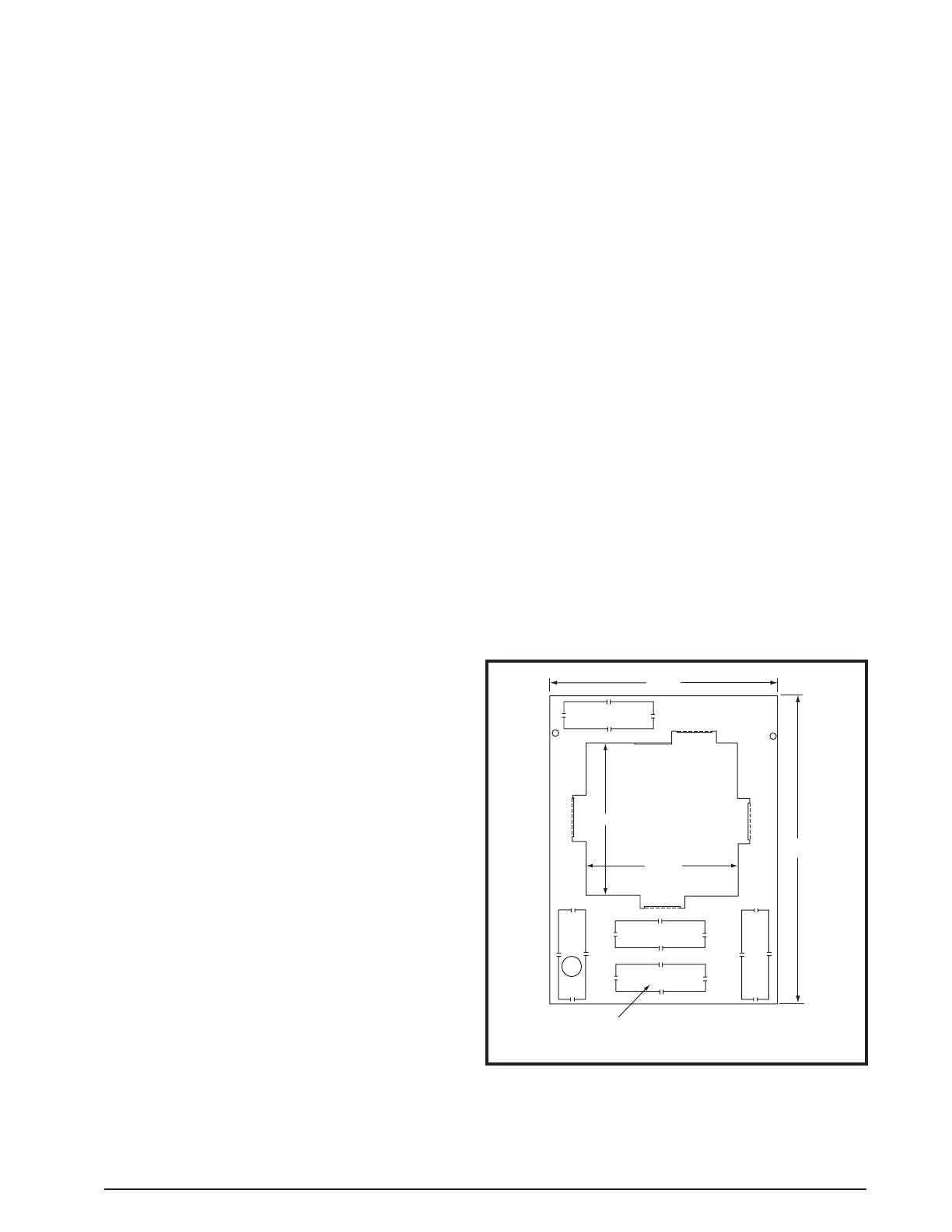
1. Usingthebasepan(Figure4)asaguide,locate and
markthe121/8”x121/8”openingfortheFeederDuct.
NOTE:Ifusingthecombustionairduct,knockoutthe
ductopeningtobeusedandmarkthe2-1/4”x7-1/4”
openingontheooralso.
2. Cutall4sidesoftheFeederDuctopening1”largerthan
thedrawncutout.NOTE:Cuttingtheopeningto14-1/8”
x14-1/8”willallowtheangesontheundersideofthe
basepantotintheopening.Cutallthewaythrough
theinsulationandbottomboardsothatthecombustion
airductisunobstructedtooutsideair.
3. If applicable, cut the 2 1/4” x 7 1/4” opening for the
combustionairduct.NOTE:Cuttheopeningfortheduct
about1/8”largerthantheactualcutoutdrawn.Thiswill
allowsomeclearancewheninstallingthefeederduct.
4. Drilla1”diameterholeforthefuellinethroughtheoor
andbottomboardtotheoutside.NOTE:Fuellinesare
notsuppliedwiththefurnace.Theyshouldbeinstalled
tocomplywithallapplicablecodes.
5. Droptransitionduct(Figure5)upsidedownthroughthe
ooropeningand centerthetopof thefeederductin
14-1/8”x14-1/8”ooropening.Usingthefeederductas
aguide,markandcuta12”x12”openinginthesupply
duct.
6. Insertthefeedertabsintothemainductandbendthem
over tightly so that the main duct edges are trapped
betweenangesandtabs.NOTE:Metaltapemaybe
beusedtoensureanairtightconnection.
7. Installthebasepanaroundthefeederduct.Securewith
2screwsintheholesneartherearofthebasepan.
8. Slitthecornersofthefeederductdowntothetopofthe
basepan(Figure6).Whilethetopofthedistributionduct
ispulledupwithonehand,benddowneachsideofthe
feederducttightlytothebasewiththeotherhand.Trim
themetaltoallowaoneinchangeoverthetopofthe
basepanandsealthatangewithmetaltape.
NOTE:Ifusinga“V”or“U”-boxcrossoversystem,use
manufacturersinstructionsforinstallationdetails.
Figure4.MA-200 Base Pan
FRONT
Combustion Air
Knock-outs
(7-1/4” X 2-1/4”)
Feeder Duct
Opening
Flue
Location
24 1/8
8 3/8
12 1/8
12 1/8
9 1/8
18 1/4
Figure5.Transition Duct
Heater Duct Below Joists
Flange
Bend
Over Tabs
Base
Floor
Joists
Slit 4 Corners
Bend Down 4 Sides
Figure6.FeederDuctInstallation
Heat Duct Below Joists
Base
Feeder Duct
Floor
Joists
Cut This Line
Bend Over
Along This Line
1"
10
InstallingtheFurnaceonanMA-100Base
1. Carefully lift the furnace over the universal base pan
andsetintoposition.Avoiddamagingthefeederduct
assembly and combustion air adapter, if present.
NOTE:Makesurethefurnaceispositionedagainstthe
backendofthebase.
2. Openthefurnacedoorandfastenthefurnacetothebase
using#8x1/2”sheetmetalscrews.
3. Using the provided hose clamp, secure the exible
combustionairtubingfromtheburnertothecombustion
airadapter.
CombustionAirDuct/PipeInstallation
The CMF3 furnace must draw the combustion air from
outside(exceptforspecialinstallations)andrequiresusing
the2”X7”rectangularcombustionairductprovidedintheMA
seriesbasekitorthedirectventkit.Ifusingtherectangular
combustionairduct,followthestepsbelow:
1. Install the combustion air duct through the selected
knockoutinthebase.Fordirectventapplications,the
rearknock-outinthefurnacebasecannotbeused.
2. Installthecombustionairadapter(afterthecombustion
air duct has been positioned) to transition the 2”X7”
openingofthecombustionairducttothe2”diameterof
theburnerexibletubing.NOTE:Adapterisincludedin
theMAseriesbasekits.Forretrotapplicationsinwhich
theMAseriesbaseisalreadyinstalled,thecombustionair
adaptercanbeorderedasakit.RefertotheReplacement
PartsListformoredetailsonorderingthiskit.
3. Securetheadapterwithwoodormetalfasteners(eld
supplied),dependinguponyourinstallation.NOTE:Make
sure the gasket for the adapter is positioned properly
beforeinstallingtheadapter.
4. Attachtheexiblehosefromtheburnertothecombustion
airadapterusingtheprovidedhoseclamp.
Figure7.MA-100UniversalBase,BottomPanel
12 1/8
Feeder Duct
Opening
18 1/4
24 1/2
12 1/8
FRONT
Combustion Air
Knock-outs
(7-1/4” X 2-1/4”)
InstallingtheFurnaceonanMA-200Base
1. Carefullyliftthefurnaceoverthebasepanandsetinto
position.Theangeonthebackofthefurnaceshould
restontheinsiderailsofthebase.
2. Raisethefrontofthefurnacetoclearthegasketonthe
bottomofthefurnaceandslidethebackuntiltherear
angedropsintothe channel at therearofthebase.
NOTE:Donotdamage the combustionairadapter,if
present,whilepositioningtheunit.Makesurethefurnace
engagesthetabsontherearangeofthebase.
3. Opentheaccessdoorandfastenthefrontofthefurnace
andthebasetotheoorwith#8x1/2”sheetmetalscrews.
4. Using the provided hose clamp, secure the exible
combustionairtubingfromtheburnertothecombustion
airadapter.
MA-100 Universal Base Installation
The MA-100 base is designed primarily for replacement
installation of the CMF3 series furnace where the
manufactured home duct system may be too small or
restrictivefor proper air ow. The MA-100 base provides
approximately4inchesofadditionalplenumspacebefore
thedischargeairenterstheductsystem.SeeFigure7.
1. Usingtheuniversalbaseasaguide,locateandmarkthe
12-1/8”x12-1/8”openingfortheFeederDuct.NOTE:If
usingthecombustionairduct,knockouttheductopening
tobeused.Thenmarkthe2-1/4”x7-1/4”openingonthe
oor.
2. Cutall4sidesoftheFeederDuctopening1”largerthan
thedrawncutout.NOTE:Cuttingtheopeningto14-1/8”
x14-1/8”willallowthefourangesontheundersideof
thepaneltotintotheopening.Cutallthewaythrough
theinsulationandbottomboardsothatthecombustion
airductisunobstructedtooutsideair.
3. If applicable, cut the 2 1/4” x 7 1/4” opening for the
combustionairduct.NOTE:Cuttheopeningfortheduct
about1/8”largerthantheactualcutoutdrawn.Thiswill
allowsomeclearancewheninstallingtheFeederDuct.
4. Drilla1”diameterholeforthefuellinethroughtheoor
andbottomboardtotheoutside.NOTE:Fuellinesare
notsuppliedwiththefurnace.Theyshouldbeinstalled
tocomplywithallapplicablecodes.
5. Set the universal base in place. Drop transition duct
(Figure5)upsidedownthroughtheooropeningand
centerthetopofthefeederductin14-1/8”x14-1/8”oor
opening.
6. Usingthefeederductasaguide,markandcuta12”x
12”openinginthesupplyduct.Removethebaseand
transitionfeederduct;thencuttheopeningintothesupply
duct.
7. Insertthefeedertabsintothemainductandbendthem
overuntilthemainductedgesaretrappedtightlybetween
anges and tabs. NOTE: Metal tape may be used to
ensureanairtightconnection.
8. Setthebottombasepaneloverthefeederduct.Slitthe
cornersofthefeederductdowntothetopofthebase.
Whilethetopofthedistributionductispulledupwithone
hand,benddowneachsideofthefeederducttightlyto
thebasewiththeotherhand.Trimthemetaltoallowone
inchangeoverthetopofthebaseandsealthatange
withmetaltape.
9. Securethetoppaneltotheoorwith2screwsthrough
thefrontange.NOTE:Ifusinga“V”or“U”-boxcrossover
system,use manufacturersinstructionsforinstallation
details.
11
SRJRoofJackInstallation
Requiredceilingandroofcut-outopeningsmustbeaccurately
locatedtopreventhazardousmisalignmentofthefurnace
and roof jack. Figure 8 displays a typical installation for
maufacturedhousingapplications.RefertoFigure9(page
12)todetermineappropriateSRJroofjackandaccessories
requiredforyourinstallation.InstallonlySRJseriesroofjack
asspeciedonthefurnacelabel.
NOTE 1:Dependingon theslopeofthe roof,aroofjack
adaptormaybeneeded.
NOTE 2:Themaximumnumberofexternalextensionkits
allowedperinstallationis2.
WARNING:
• Theroofjackandventpipeasdeterminedfrom
thechartinFigure9mustbeapplied.
• Theindicatinglinenearthebottomoftheroof
jackmustextendbelowthenishedceiling.
• Theventpipemustbeattachedtothefurnace
uecollarwithprovidedsheetmetalscrews.
• DONOTinstallanyelbows(adjustableornon-
adjustable) or a stack damper in the venting
system.
1. Measureandcut an81/4”diameter holethroughthe
roofandceilingthatisalsoin direct line with theue
connectiononthetopofthefurnace.
2. Centertheadaptoropeningovertheroofopening.Use
sealantorcaulkingundertheadaptor.Useroongnails
orscrewsonwoodconstructionorsheetmetalscrews
onmetalroofs.
3. Inserttheventpipeintothebottomoftheroofjackwith
lockingslotpointedtowardsfurnace.Slidethepipeinto
theroofjacktoalengththatallowsconvenientreachto
theconnectionatthetopofthefurnace.
4. Ease the roof jack assembly through the openings.
NOTE: Thelowerportionoftheouterbarrelmustextend
throughthenishedceilingasindicatedonthebarrel.
Usesealantorcaulkingontherooforadaptortoseal
undertheashingoftheroofjackassembly.
5. Extendtheventpipeuntilthelockingslotengagesthe
screwinthetopofthefurnaceuepipe.
6. Twisttheventpipetolockthetwopipestogetherand
tightenthescrew.Alljointsandconnectionsshouldbe
inspectedbeforestartupofthefurnace.SeeFigure10
&Figure11(page12).
7. Fastentheceilingtrim/restopplatesaroundtheupper
barrelwithfournailsorwoodscrews(eldsupplied).
NOTE:ThetopsectionofroofjackmodelsSRJ-3,-4,
and-5canberemovedfordwellingtransit.Ifthetopis
removed,remainingopeningsmustbesealedfromrain,
debris,etc.,untilthetopisreinstalled.Aplasticaccessory
capmustbefastenedtothelowerroofjacksectionusing
thesamescrewssecuringtheroofjackcapassembly.
IMPORTANT NOTE:
Whenthetopsectionoftheroofjackisremovedfor
transit,aspecialwarninglabelmustbeattachedadjacent
tothefuellineconnectionofthegasoroilburner.The
special warning label is supplied with two piece roof
jackassemblies.
DamperInstallation
Anautomaticshut-offdamperisavailable(seereplacement
partslist).Anautomatedshutoffdamperisrequiredwhen
thehomeis airconditionedbyaself-containedunit.This
damperisdesignedtotinthefeederductcavity,directly
underthefurnace.Adamperisrequiredtopreventchilled
airfromowingoverthefurnaceheatexchanger.Forproper
installation,refertotheinstructionsprovidedwiththedamper.
Flashing
Barrel
Ceiling Plate
Vent
Ventilation
Knock-Out
DUCT
CONNECTOR
Return Air
Grille and
Filter
Power Supply
Connection
Access
Door
Base Pan
Fuel Line
Feeder Duct
Combustion
Air Duct
FURNACE
ASSEMBLY
ROOF JACK
ASSEMBLY
Combustion Air
Adapter (Not Shown)
is to be Installed
Over Combustion
Air Duct
Figure8.TypicalFurnaceInstallationfor
ManufacturedHousingApplications

12
RA-S4
RA-S3
RA-S2.5
4/12
3/12
2-1/2/12
None
Flat
NOTES:
SRJ1 & SRJ2 Models are one piece construction
SRJ3, SRJ4, & SRJ5 Models are two piece construction
-C Models are two piece construction
OPTIONAL:
Add -C for Raised Inlet Models (Example: SRJ3-34-C)
RoofJack Adaptor (for mounting roof jack on pitched roof)
Protective Cap (used when top of roofjack is removed)
Use Adaptor
Model No.
When roof pitch is:
1/2 Minimum
Furnace
CMF Series
57"
And Ceiling
Height is:
Add Suffix
For Vent Pipe
7'
-28
7'6"
-34
8'
-40
Ceiling Trim Plates
When Ceiling
Cavity is:
Use Roof Jack
Model No.
49" to 59"
37" to 48"
SRJ5
25" to 36"
13" to 24"
12" or Less
SRJ4
SRJ3
SRJ2
SRJ1
Adaptor
14" Removable SRJ3, SRJ4, & SRJ5
25" Removable All -C Models
Figure9.SelectionofRoofJack&AccessoriesChart
Figure11.VentPipeInstallation
Flue Pipe
of Furnace
Vent Pipe
Tu rn To Lock-
Tighten Screw
Insert Sliding Pipe
Fasten Ceiling
Trim Plates
Ceiling
Roof
Roof Jack Adaptor
Install With Line
Below Ceiling
Remove three screws
to separate two piece
models; replace with
protective cap for
transit only
Fasten roof flashing to adaptor
or flat roof; apply sealant or
caulking underneath
Fasten adaptor to
sloped roof; apply
sealant or caulking
underneath
Figure10.RoofJack

13
FUEL CONNECTIONS
Gaspiping-PGSeriesOnly
WARNING:
FIRE OR EXPLOSION HAZARD
• Failuretofollowsafetywarningsexactlycould
resultinseriousinjuryorpropertydamage.
• Installationandservicemustbeperformedby
aqualiedinstaller,serviceagencyorthegas
supplier.
• Donotstoreorusegasolineorotherammable
vaporsandliquidsinthevicinityofthisorany
otherappliance.
WHAT TO DO IF YOU SMELL GAS
• Donottrytolightanyappliance.
• Donottouchanyelectricalswitch;donotuse
anyphoneinyourbuilding.
• Leavethebuildingimmediately.
•Immediately call your gas supplier from a
neighbor’s phone. Follow the gas supplier’s
instructions.
• Ifyoucannotreachyourgassupplier,callthe
redepartment.
• Allgaspipingmustbeinstalledincompliancewith
localcodesandutilityregulations.Intheabsenceof
localcodesthegaslineinstallationmustcomplywith
thelatesteditionoftheNationalFuelGasCode(ANSI
Z223.1)or(CAN/CSAB149.1or.2)InstallationCodes
andHUDGasPipingSystems(3280.705).
• Some local regulations require the installation of a
manual main shut-off valve and ground joint union
externaltothefurnace.Theshut-offvalveshouldbe
readilyaccessibleforserviceand/oremergencyuse.
Consultthelocalutilityorgassupplierforadditional
requirementsregardingplacementofthemanualmain
gasshut-off.
• Gas piping must never run inorthroughairducts,
chimneys,gasvents,orelevatorshafts.
• Compounds used on threaded joints of gas piping
mustberesistanttotheactionsofLPpropanegas.
• Themaingasvalveandmainpowerdisconnecttothe
furnacemustbeproperlylabeledbytheinstallerin
caseemergencyshutdownisrequired.
• Flexiblegasconnectorsarenotrecommendedforthis
typeoffurnacebutmaybeusedifallowedbylocal
jurisdiction. Only new exible connectors may be
used.Donotuseaconnectorwhichhaspreviously
servicedanothergasappliance.
• Adriplegshouldbeinstalledintheverticalpiperun
totheunit.
TheCMF3furnacemaybeinstalledwithgasentrythrough
the bottom of the furnace. When installing the gas line,
connectaseparategaslinefromthegasmetertotheburner
withamanualshut-offvalveinstalledinthesupplylineat
thefurnace.Alwaysusenewcleanpipingandroutetheline
inaneasilyaccessiblemanner.Thepipingandthreading
mustbefreefromcuttingburrsanddefects.Thelinemust
bedurable,substantial,andgastight.Anadditionalmain
manualshut-offvalvemaybeinstalledinthegassupplyline
toshut-offthemainfuelsupply,ifdesiredbythehomeowner
orrequiredbylocalcodes.
Thepropergassupplylinesizecanbedeterminedbyreferring
tothelatesteditionoftheNationalFuelGasCode(NFGC)
andHUDGasPipingSystems(3280.705).Blackpipeisthe
mostpracticalfornaturalgas,becauseofthelargersizes
required. Copper tubing with an internal coating of tin is
recommendedforusewithpropane(LP)gasinstallations.
LeakCheck
WARNING:
ELECTRICAL SHOCK, FIRE OR
EXPLOSION HAZARD
Failuretofollowsafetywarningsexactlycould
resultinseriousinjuryorpropertydamage.
Improper servicing could result in dangerous
operation, serious injury, death or property
damage.
• Beforeservicing,disconnectallelectricalpower
tofurnace.
• Whenservicingcontrols,labelallwiresprior
todisconnecting.Reconnectwirescorrectly.
• Verifyproperoperationafterservicing.
Afterthegaspipingtothefurnaceiscomplete,allconnections
mustbetestedforgasleaks.Thisincludespipeconnections
atthemaingasvalve,emergencyshutoffvalveandexible
gasconnectors(ifapplicable).Thesoapandwatersolution
canbeappliedoneachjointorunionusingasmallpaintbrush.
Ifanybubblingisobserved,theconnectionisnotsealed
adequatelyandmustberetightened.Repeatthetightening
andsoapcheckprocessuntilbubblingceases.
IMPORTANT NOTE:
Whenpressuretestinggassupplylinesatpressures
greater than 1/2 psig (14 inch W.C.), the gas supply
pipingsystemmustbedisconnectedfromthefurnace
topreventdamagetothegascontrolvalve.Ifthetest
pressureislessthanorequalto1/2psig(14inchW.C.),
closethemanualshut-offvalve.
HighAltitudeApplication
Installation of this furnace at altitudes above 2,000 feet
shallbeinaccordancewithlocalcodes,orintheabsence
oflocalcodes,theNationalFuelGasCode,ANSIZ223.1/
NFPA54orNationalStandardofCanada,NaturalGas&
PropaneInstallationCodeCSAB149.1.Pleaseconsultyour
localcodeauthority.
WARNING:
Thereductionofinputratingnecessaryforhigh
altitudeinstallationmayonlybeaccomplishedwith
factorysuppliedorices.Donotattempttodrillout
oricesintheeld.Improperlydrilledoricesmay
causere,explosion,carbonmonoxidepoisoning,
personalinjuryordeath.
TheCMF3furnaceisshippedfromthefactorywithitsorices
andgasregulatorsettingfornaturalgasoperationatsea
levelaltitudes.At2,000feet,theNFGCrequiresthatthis
appliancebederated4%foreach1,000feetofaltitude.For
example,theinputneedstobereduced8%at2,000feet,
14
12%at3,000feet,etc.Thisderationisinreferencetothe
inputrateandgasheatingvalueatsealevel.
Highaltitudeconversionforthisfurnacerequiresreducing
theoricesizeordecreasingthemanifoldpressure.When
decreasingthemanifoldpressure,thepressuremustnotbe
setbelow3.2inWC.Ifthepressureneedstobesetbelow
3.2inWCtoachieveproperderation,thenchangetheorice
sizeandraisethemanifoldpressurebackto3.5inWC.
Afterchangingtheregulatorpressureortheorices,itis
requiredthatyoumeasurethegasinputrate.Thismaybe
accomplishedintheusualway,byclockingthegasmeter
andusingthelocalgasheatingvalue.Tochecktheinputof
thefurnaceseepage21.
IMPORTANT NOTE:
Observetheactionoftheburnerstomakesurethereis
noyellowing,liftingorashbackoftheame.
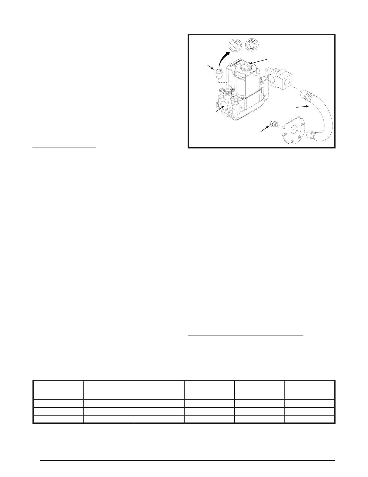
ConvertingtoLPGas
TheCMF3furnaceisshippedfromthefactoryforusewith
naturalgasbutcanbeconvertedtouseliquidpropanegas.
UsethefollowingprocedureandFigure18forconverting
thegasburner.
1. SetthermostattoOFF.
2. Turnoffallpowertothefurnace.
3. Openfurnacedoorandlocatethegasvalve.
4. PushinonthegasknobandturnittoOFF.
5. Shutoffgassupplyatmeter.
6. Disconnectgasburnerelectriccord,gaspipingtoburner,
andthermostatleads.
7. Removenutssecuringburnerinplace.
8. Disconnectinletpipeunionatburner.
9. Disconnectthetwowiresleadingtogascontrolvalve.
10.RemoveboltssecuringU-shapedmanifoldplatetoorice
assembly.
11.Removethemainoriceandreplaceitwiththecorrect
LPfueloriceasshowninTable2.Refertotherating
plateonthefurnacetodeterminetheringrateforyour
application.NOTE:Iftheringrateofyourfurnacehas
beenconverted,make suretheappropriateLPorice
forthenewringrateisinstalled.
12.Removetheregulatorconverterontopofthegasvalve.
Inverttheconvertersothattheredringwillbelocatedat
thebottomandtheLPstampingontheconverterappears
up.
13.Screwconverterbackintotheregulator,handtightplus
1/8turn.
14.Reinstalltheburnerassemblyintothefurnace.
15.Reconnectthegaspipingandelectricalwirestothegas
valve.
16.Openthemanualshut-offvalveandfollowtheOperating
Instructionsoutlinedonpage18.
Oilpiping-POSeriesOnly
Thefollowingproceduresarerecommendedasgoodpractice.
However,requirementsoflocalcodesandordinances,H.U.D.
ManufacturedHomeandSafetyStandardsorNationalFire
ProtectionAssociationmustbesatised,wheretheyapply,
foranapprovedinstallation.
• Use a tank capacity suitable for the application with a
weatherproof,cappedllopeningandshieldedventtolet
airinasfuelisused.NOTE:Theinsideofthetankmust
becleanbeforelling.Allwater,rust,sediment,andother
foreignmattermustbeushedout.
• If a two pipe system is used or if oil is taken from the
bottom of the tank, a lter is recommended. A manual
shut-offvalvemayalsobeusedonasinglepipeortwo
pipesystem.NOTE:Localcodesmaydictatethespecic
installationrequirements.
• Afuelortankgaugeisrecommendedforeasychecking
ofthefuellevel.Checkthegaugeusingadipstick.
• Locatethestoragetankconvenientlynearthehome.For
above ground fuel tank installations, the tank may rest
threetofourinchesofftheground.Fueltanksmayalso
beburiedifproperlycoatedtoresistcorrosion.Forbelow
groundfueltankinstallations,theverticaldimensionfrom
thebottomofthetanktothefuelpumpmustnotexceed
10feet.Keepthetanklledespeciallyinthesummerto
reducetheaccumulationofcondensation.
FuelLineHook-Up:SingleLineSystem
Thesinglelinesystemishighlyrecommendedwhenvertical
lift,frombottomoftanktopump,islessthan8feet.Asingle
linehookuphastheadvantageofcostinglessandgiving
quieteroperation.
Table2.Natural&LPGasOrices
BURNER
DESIGNATION
FIRING RATE
INPUT (BTUH)
NATURAL GAS
ORIFICE NUMBER
NATURAL GAS
TIME TO CONSUME*
LP GAS
ORIFICE
NUMBER
LP GAS
TIME TO CONSUME**
GasGun-60-DI-S 60,000 27 60 43 148
GasGun-70-DI-S 70,000 22 52 41 126
GasGun-75-DI-S 75,000 20 48 40 120
*Timesarebasedonnaturalgasatanaverageof1,000BTUpercubicfoot,aburnermanifoldpressureof3.5inWC,and1CFM.
**TimesarebasedonLPgasatanaverageof2,500BTUpercubicfoot,aburnermanifoldpressureof10inWC,and1CFM.
Figure12.LP & Natural Gas Conversion
Orifice
Inlet
U-Shaped
Manifold
Regulator
Converter
Gas Control Knob
15
FuelLineHook-Up:TwoLineSystem
Twolinesystemsshouldonlybeusedwhentheverticallift
exceeds8feet.
1. Install the oil feed line as outlined in the Hook-up
Procedure.
2. Installtheoilpumpbypasspluginthebottomreturnport.
3. Runthereturnlineupthroughthefurnacebasetothe
returnportofthepump.Runtheotherendofthelineto
thetank,using3/8”O.D.coppertubingor1/4”pipewith
theendscapped,androutingthelinesoitstaysclean.
4. Insertthereturnlinethroughthesecondopeninginthe
duplexbushing.Ifthebottomofthetankislowerthanthe
pumpintake,thetubeshouldbeinserted3or4inches
fromthetankbottom.Ifthebottomofthetankishigher
thanthepumpintake,thereturnlineshouldextendnot
morethan8”insidethetank.
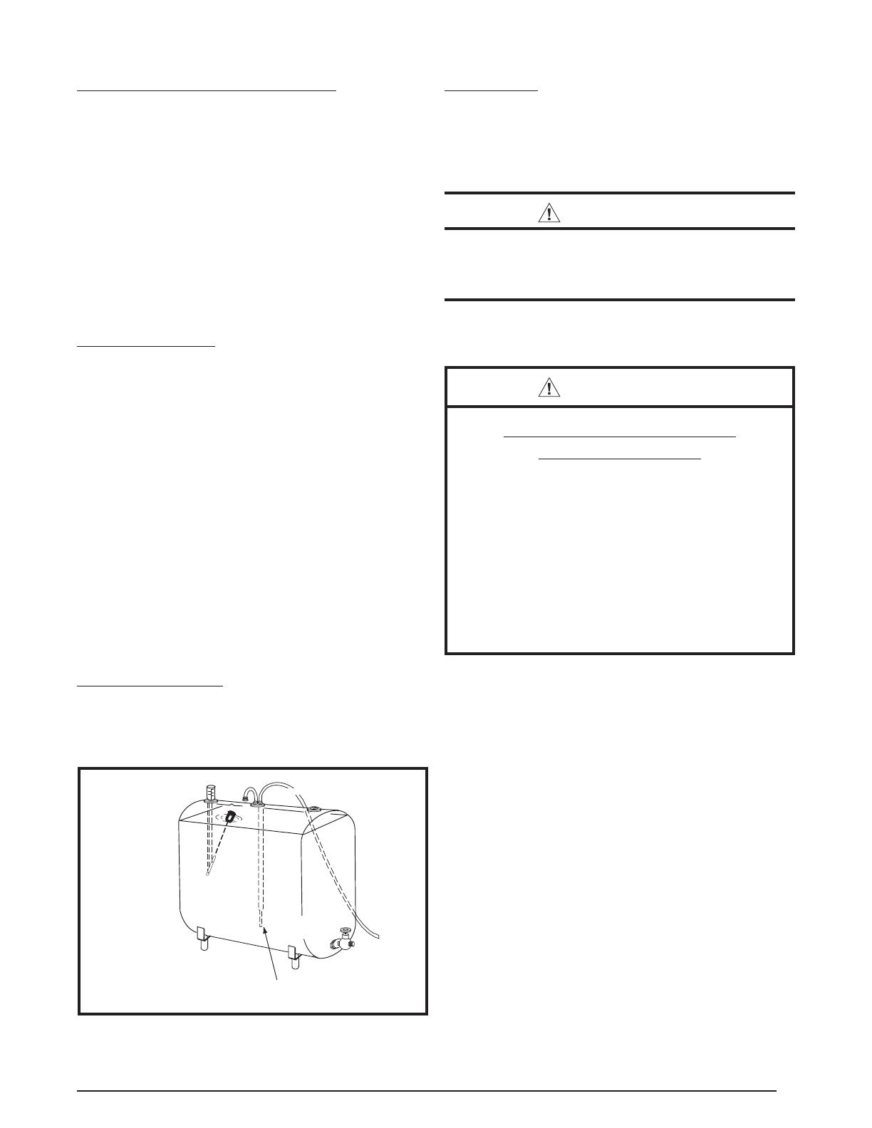
Hook-UpProcedure
1. Use3/8”O.D.coppertubingforthefuelline.Captheend
withtapetokeepoutdirtwhilethelineisbeingrouted.
SeeFigure13.
2. Installduplexbushingfortwo3/8”linesinthetoptting
ofthetank.
3. Insertoneendofthetubingthroughtheduplexbushing
until it is 3” to 5” from the bottom drain. Tighten the
bushing.
4. Routethefuellinewhereitwillnotbesubjecttodamage.
Makeallbendsgradualandavoidkinksthatmightrestrict
oilow.
5. Opentheburneraccessdoor.Connecttheoillinetothe
intakeportonthepump.Tightenotherportplugsonthe
pump.
6. Makesuretheoillineisairtight!NOTE:Airleakscancause
thepumptoloseprimeandwillcreateotherproblems
suchasnozzlefailure,odors,rumblingnoise,andfalse
safetyshutdown.
7. Inserttheshortlengthofthecoppertubelevelwiththe
bottomoftheduplexbushing.Tightenthebushing.Form
thetubeintoaninverted“U”toserveasavent.
EliminatingAirLeaks
To eliminate problems caused by air in the oil line, all
connectionsinthe oilsupplylineandallplugs,nuts, and
ttingsonthepumpmustbeairtight,includingthenutthat
coversthepressureadjustment.Itisimportantthatthehook-
upbedonewithagoodaringtool.
Figure13.RecommendedTankHook-Up
200-300GallonTank
Drain
End of Oil Supply Line
3" to 5" Above
Bottom Drain
Guide pipe
Gauge
Vent with
Cap
2" Duplex
Bushing
2" Fill
3/8" Oil Supply Line
Note: Additional venting may
be required if tank is filled rapidly.
FuelOilType
GradeNo.1maybeusedwheretheoilsupplyissubject
tolowtemperatures.DonotusefueloilheavierthanGrade
No.2.Biodieselblendsupto5%(B5)arealsoacceptable.
IMPORTANT NOTE:
DO NOT USE GASOLINE, CRANKCASE OIL, OR ANY
OILCONTAININGGASOLINE.
WARNING:
Failuretokeepsupplyoilcleanmaycausefailureof
certaincomponentssuchasthefuelpumpgears,
checkvalve,shaftseal,orburnernozzlewhichmay
resultinaburnerre.
ELECTRICAL CONNECTIONS
WARNING:
ELECTRICAL SHOCK, FIRE OR
EXPLOSION HAZARD
Failuretofollowsafetywarningsexactlycould
resultinseriousinjuryorpropertydamage.
Improper servicing could result in dangerous
operation, serious injury, death or property
damage.
• Beforeservicing,disconnectallelectricalpower
tofurnace.
• Whenservicingcontrols,labelallwiresprior
todisconnecting.Reconnectwirescorrectly.
• Verifyproperoperationafterservicing.
• Electrical connections must be in compliance with
all applicable local codes and ordinances, and with
the current revision of the National Electric Code
(ANSI/NFPA70).
• For Canadian installations, the electrical connections
and grounding shall comply with the current Canadian
ElectricalCode(CSAC22.1and/orlocalcodes).
Pre-ElectricalChecklist
√Verify the voltage, frequency, and phase of the supply
sourcematchthespecicationsontheunitratingplate.
√Verifythattheserviceprovidedbytheutilityissufcient
tohandletheadditionalloadimposedbythisequipment.
Refer to the unit wiring label or Table 3 (page 19) for
properhighandlowvoltagewiring.
√Verifyfactorywiringisinaccordancewiththeunitwiring
diagram(Figure18,page25).Makesurenoconnections
loosenedduringshippingorinstallation.
16
LineVoltage
• Anelectricaldisconnectmustbelocatedwithinsight
ofandeasilyaccessibletotheunit.Thisswitchshall
be capable of electrically de-energizing the unit. See
unitdatalabelforproperincomingeldwiring.Anyother
wiringmethodsmustbeacceptabletoauthorityhaving
jurisdiction.
• Itisrecommendedthat thelinevoltageto theunitbe
suppliedfromadedicatedbranchcircuitcontainingthe
correctfuseorcircuitbreakerfortheunit.SeeTable3
forunitspecications.
• Overcurrentprotectionmustbeprovidedatthebranch
circuitdistributionpanelandsizedasshownontheunit
ratinglabelandaccordingtoapplicablelocalcodes.
• Useonlycopperwireforthelinevoltagepowersupply
tothisunit.Use14-2TypeNMcableor codeagency
listed conduit and a conduit connector for connecting
thesupplywirestotheunit.
• Ifreplacinganyoftheoriginalwiressuppliedwiththeunit,
thereplacementwiremustbecopperwireconsistingof
thesamegaugeandtemperaturerating.
• Provide power supply for the unit in accordance with
theunitwiringdiagram, andtheunitrating plate.The
installershouldbecomefamiliarwiththewiringdiagram/
schematicbeforemakinganyelectricalconnectionsto
theunit.SeeFigure18(page25).
Wiring Connections
1. Opentheappliancedoorforaccesstothecontrolbox.
2. Removethecontrolboxcover.
3. Connecttheblackwireofthefurnacetotheblackwire
ofthepowersupplycable.
4. Connectthethewhitewireofthefurnacetothewhite
wireofthepowersupplycable.
5. Connectthegroundwireofthepowersupplycableto
thegreenscrewinthecontrolboxofthefurnace.
6. Verifyallelectricalconnectionsaresecurelyconnected.
7. Replacethecontrolboxcover.
Grounding
WARNING:
The unit cabinet must have an uninterrupted or
unbrokenelectricalgroundtominimizepersonal
injuryifanelectricalfaultshouldoccur.Donotuse
gaspipingasanelectricalground!
Thisunitmustbeelectricallygroundedinaccordancewith
localcodesor,intheabsenceoflocalcodes,withtheNational
ElectricalCode(ANSI/NFPA70)ortheCSAC22.1Electrical
Code.Usethegroundinglugprovidedinthecontrolboxfor
groundingtheunit.
ThermostatConnections
• Thermostatconnectionsshallbeinaccordancewiththe
instructionssuppliedwiththethermostatandtheindoor
equipment. The low voltage wires must be properly
connectedtotheunitslowvoltageterminalblock.Route
R&Wfromthethermostattotheburnercompartment.
Connect R to one of the low voltage terminals of the
burner. Connect W to the burner’s other low voltage
terminal.
• A single stage thermostat is used with this equipment
and must operate in conjunction with any installed
accessories.
• The thermostat should be mounted about 5 feet above
theooronaninsidewall.DONOTinstallthethermostat
on an outside wall or any other location where its
operationmaybeadverselyaffectedbyradiantheatfrom
replaces, sunlight, or lighting xtures, and convective
heat from warm air registers or electrical appliances.
Refertothethermostatmanufacturer’sinstructionsheet
fordetailedmountingandinstallationinformation.
HeatAnticipator
Settheheatanticipatoraccordingtotheinstructionssupplied
by the thermostat manufacturer. To determine the heat
anticipatorsetting:
1. Addthecurrentdrawofthesystemcomponents;or
2. MeasurethecurrentowonthethermostatR-Wcircuit
afterthecirculatingblowermotorhasstarted.
BlowerSpeed
TheCMF3furnaceisequippedwitha3speedPSCmotor
thatispre-setatthefactoryforMEDIUMspeedoperation.
Foroptimumsystemperformanceandcomfort,itmaybe
necessary to change the factory speed setting. This is
accomplishedbychangingawireconnectionattheblower
motor.Refertothewiringdiagramlabelontheinsideofthe
paneldoororseeFigure18(page29)forwiringconguration.
Table4liststhepropercirculatingairowandtemperature
risefortheCMF3furnace.
CMF 70 PG
CONVERTIBLE
CMF 70 PO
CONVERTIBLE
FactorySetFiringRate(btu/hr)* 70,000 70,000
HeatingCapactiy(btu/hr) 56,000 56,000
KitConvertedFiringRate(btu/hr)**
60,000
or
75,000
60,000
AFUERating(%) 80+ 80+
OriceNumber(NaturalGas) 22 N/A
OriceNumber(PropaneGas) 41 N/A
BurnerNozzleforOil N/A
0.50gph;
A;80
o
BlowerDxW 10x7 10x7
MotorH.P.-Speed-Type 1/4-3-PSC 1/4-3-PSC
MotorFLA 3.3Amps 3.3Amps
FuseorBreaker 15Amps 15Amps
Nom.AnticipatorSetting 0.6 0.6
TemperatureRiseRange(
o
F) 55
o
-85
o
55
o
-85
o
NOTES:
Electrical:Allmodelsare115volt,60Hz,1phase.
Thermostatcircuitis24VAC,60Hz.
Gasconnection:1/2”NPT.
* Ratingsto2,000feet.Over2,000ft,reduceratingsby4%foreach
additional1,000ftabovesealevel.
** TheringrateoftheCMF70seriesfurnacecanbechangedusing
anapprovedconversionkit.
AFUE=AnnualFuelUtilizationEfciency
Table3.CMF3Specications

17
CAUTION:
Toavoidpersonalinjuryorpropertydamage,make
surethemotorleadsdonotcomeintocontactwith
anyuninsulatedmetalcomponentsoftheunit.
• High Speed Operation:Connecttheblackwirefromthe
fanswitchtotheblackwireoftheblowermotor.
• Medium Speed Operation: Connect the black wire
fromthefanswitchtothebluewireoftheblowermotor.
NOTE: Thisisthefactorydefaultsettingandshouldnot
bechangedifhighspeedoperationisdesired.
• Low Speed Operation:Connecttheblackwirefromthe
fanswitchtotheredwireoftheblowermotor.
ConstantBlowerOperation
TheFANON&OFFswitchislocatedontopofthecontrol
box.Thisswitchprovideseitherautomaticoperationofthe
blowerthroughthethermostatorconstantbloweropeation.
Table4.CMF3 Airflow Data
EXTERNAL
STATIC
PRESSURE
(IN WC)
AIRFLOW (CFM)
LOW SPEED
FOR
60 KBTU/H INPUT
MEDIUM SPEED
FOR
70 KBTU/H INPUT
HIGH SPEED
FOR
75 KBTU/H INPUT
0.1 710 740 820
0.2 670 700 780
0.3 640 660 730
0.4 600 620 680
0.5 550 570 630
0.6 500 520 570
START-UP & ADJUSTMENTS
WARNING:
Allsafetyinformationmustbefollowedduringthe
start-upandoperationofthefurnace.Unqualied
individualsshouldnotattempttointerpretthese
instructions. Improper servicing could result in
dangerousoperation,propertydamage,personal
injuryordeath.
WARNING:
FIRE OR EXPLOSION HAZARD
• Failuretofollowsafetywarningsexactlycould
resultinseriousinjuryorpropertydamage.
• Installationandservicemustbeperformedby
aqualiedinstaller,serviceagencyorthegas
supplier.
• Donotstoreorusegasolineorotherammable
vaporsandliquidsinthevicinityofthisorany
otherappliance.
WHAT TO DO IF YOU SMELL GAS
• Donottrytolightanyappliance.
• Donottouchanyelectricalswitch;donotuse
anyphoneinyourbuilding.
• Leavethebuildingimmediately.
•Immediately call your gas supplier from a
neighbor’s phone. Follow the gas supplier’s
instructions.
• Ifyoucannotreachyourgassupplier,callthe
redepartment.
• Thisappliancedoesnothaveapilot.Itisequippedwith
anignitiondevicewhichautomaticallylightstheburner.
Donottrytolighttheburnerbyhand.
• BEFORELIGHTINGOROPERATINGsmellallaround
theapplianceareaforgas.Besuretosmellnexttothe
oorbecausesomegasisheavierthanairandwillsettle
ontheoor.
• Useonlyyourhandtopushinandmovethegascontrol
lever.Neverusetools.Iftheleverwillnotpushinbyhand,
don’t try to repair it, call a qualied service technician.
Forceorattemptedrepairmayresultinareorexplosion.
• Shouldoverheatingoccur,orthegassupplyfailtoshut
off,turnthemanualgasvalvetotheapplianceOFF.
Pre-StartCheckList
√Verifythepolarityoftheconnectionsarecorrect,theline
voltage power leads are securely connected and the
furnaceisproperlygrounded.
√Verify the thermostat wires (R & W) are securely
connectedintheburnercompartment.
√Verifythegaslineservicepressurebeforethefurnaceis
running:
For natural gas, the pressure should not exceed 10.0
inchesofW.C.,andisnotlessthan3.5inchesW.C.
ForLPgas,thelineservicepressuremustnotexceed14
in.W.C.,andmustnotbelessthan11.0in.W.C.

18
√Verify the roll-out and manual reset switchis closed. If
necessary, press the red button to reset a switch. DO
NOTinstallajumperwireacrossaswitchtodefeat
its function. If a switch reopens on startup, DO NOT
reset the switch without identifying and correcting the
faultcondition.
√Verifytheblowerdoorisinplace,closingthedoorswitch
inthelinevoltagecircuit.
√Verifythegaslineandallconnectionsareleakfree.
Operating Instructions for PG Direct Ignition
Burner
Do not perform these steps until all of the safety checks
havebeencompleted:
1. STOP!Readallsafetyinformationonthispage.
2. SetthethermostattoOFFortoitslowestsetting.
3. Turnoffallelectricpowertotheappliance.NOTE:This
appliance is equipped with an ignition device which
automaticallylightstheburner.DONOTtrytolightthe
burnerbyhand.
4. Turnthelatchandopenthefurnacedoor.
5. Push in the gas control knob and turn to OFF.
IMPORTANT:DONOTFORCE.Wait10minutesto
clearoutanygas.Ifyoustillsmellgas,STOP!and
readWHATTODOIFYOUSMELLGAS.Ifyoudon’t
smellgas,gotothenextstep.
6. TurnthegascontrolknobtoON.
7. Closethefurnacedoorandturnthelatch.
8. Turnonallelectricpowertotheappliance.
9. TurnthethermostattoONandsettothedesiredsetting.
10.Iftheappliancewillnotoperateafteronere-try,follow
theinstructionsShuttingOfftheGasSupplybelowand
callyourservicetechnicianorgassupplier.
ShuttingOfftheGasSupply
1. SetthethermostattoOFFortoitslowestsetting.
2. Turnoffallelectricpowertotheapplianceifserviceis
tobeperformed.
3. Turnthelatchandopenthefurnacedoor.
4. PushinthegascontrolknobandmovetoOFF.DONOT
FORCE.
5. Closethefurnacedoorandturnthelatch.
CheckingtheInputoftheFurnace
Refertothefurnaceratingplatetodeterminetheringrate
of the furnace. Using Table 2 (page 14), determine the
appropriateoricesizefortheringrateandgasbeingused
inyourapplication.Checktheburneroricetoensurethatit
isthecorrectsize.Theinputofthisfurnacecanbechecked
usingthefollowingsteps:
1. Shutoffallothergasredappliances.
2. Startthefurnacerunitforatleast3minutes.
3. Measurethetime(inseconds)requiredforthegasmeter
tocompleteonerevolution.NOTE:Onerevolutionequals
1cubicfootofgas.
4. Comparethetimemeasuredwiththeappropriatetime
listedinTable2(page14).Ifthetimevariesbymorethat
5%fromthetimesshowninthetable,thenmeasurethe
inletandgasvalvemanifoldpressures.SeeCheckingthe
InletGasPressureandCheckingtheManifoldPressures
sectionsbelow.
WARNING:
Donotattempttodrillthegasorices.Useonly
factorysuppliedorices.Improperlydrilledorices
may cause fire, explosion, carbon monoxide
poisoning,personalinjuryordeath.
5. Iftheinletgaspressureandthemanifoldpressureare
bothproperlyset,thenchecktheburneroricetoensure
thatitisproperlysized.Furthergasproblemsshouldbe
referredtothelocalgassupplier.
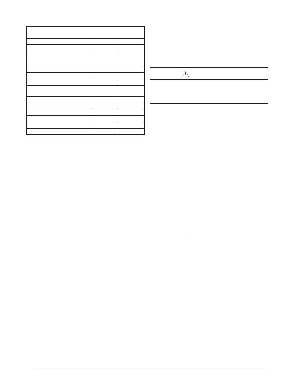
CheckingtheInletGasLinePressure
Theinletgaslinepressurecanbecheckedattheportlocated
ontheinletendofthegasvalve.SeeInstallingthePressure
GaugeorU-TubeManometersection.
• Natural gas installations:Theinletgaslinepressureat
thegasvalvemustbebetween5in.W.C.&7in.W.C.
• LP gas installations:Theinletgaslinepressureatthe
gasvalvemustbebetween11in.W.C.&13in.W.C.
CheckingtheManifoldPressure
Themanifoldpressurecanbecheckedattheportlocatedon
thegasoutletendofthegasvalveusingapressuregauge
orU-tubemanometer.Ifthemanifoldpressureisnotequal
tothevaluesbelow,thenitmustbeadjusted.SeeInstalling
thePressureGaugeorU-TubeManometer.
• Natural gas installations:Themanifoldpressuremust
besetat3.5in.W.C.
• LP gas installations:Themanifoldpressuremustbeset
at10.0in.W.C.
InstallingthePressureGaugeorU-Tube
Manometer
1. Determinewhichtypeofpressure(inletgasormanifold
pressure)needstobemeasured.
2. Usinga3/16”Allenwrench,removetheappropriatetap
pluglocatedonthegasvalve.SeeFigure14(page19).
NOTE:Tomeasuretheinletgaspressure,removethe
tapplugontheinletsideofthegasvalve.Tomeasure
themanifoldpressure,removethetapplugontheoutlet
sideofthegasvalve.
3. Installattingthathasa1/8”NPTpipethreadandis
compatiblewiththepressuregaugeorU-tubemanometer
onthevalve.
4. ConnectthepressuregaugeorU-tubemanometertothe
gasvalve.Refertothegaugemanufacturer’ssupplied
instructionsforproperhookupandusage.
5. Aftermeasuringthepressure,removethepressuregauge
orU-tubemanometerfromthegasvalveandreplacethe
tapplug.NOTE:Makesurethetapplugistightandisn’t
cross-threaded.
AdjustingtheBurner
Theairshutterofthegasgunburnerispre-setatthefactory
andshouldnotbeadjustedunlesstheringrateofthefurnace
needstobeconverted.Theburnershouldrunquietly.Verify
theairshuttersettingiscorrectasshowninTable5(page
19).NOTE:Itisveryimportantthatthereisanamplesupply
ofcombustionairwithoutdecreasingburnerefciency.An
inadequateamountoffreshaircancausecarbonmonoxide
(CO)production.Thecarbondioxide(CO
2)contentoftheue
productsshouldbeintherangeof8.5%to9.5%fornatural
gasor9.0%to10.0%forLPgas.
19
INLET
TA P
OUTLET
TA P
Regulator
Converter
Figure14.DirectIgnitionGasValve
WARNING:
Donotattempttodrillthegasorices.Useonly
factorysuppliedorices.Improperlydrilledorices
may cause fire, explosion, carbon monoxide
poisoning,personalinjuryordeath.
At 2,000 feet, the NFGC requires that this appliance be
derated4%foreach1,000feetofaltitude.Forexample,the
inputneedstobereduced8%at2,000feet,12%at3,000
feet,etc.Thisfurnacecanbederatedbyreducingtheorice
sizeordecreasingthemanifoldpressure.
OperatingInstructionsforPOOILBurners
OilburnersinPOseriesfurnacesarefactoryequippedwith
aprimarycontrolcapableofeitherintermittentorinterrupted
ignition.
Start-UpProcedure
1. Openallmanualshut-offvalvesintheoilsupplylinefrom
thetanktotheburner.
2. TurnONtheelectricalsupplytothefurnace.
3. Settheroomthermostattothedesiredtemperature.
Air-BleedProcedure-SinglePipeInstallation
1. Openthedoortothefurnace.
2. Attach1/4”I.D.plastictubeovertheendoftheairbleed
valveontheoilpumpasshowninFigure15.Placethe
otherendofthetubeinalargecontainer.
3. Pressthedoorswitchintostarttheburner.
4. Turntheairbleedvalveopennotmorethan1/2turnto
getafastowofoilintothecontainer.
5. To assure continuous operation, use a wire to jump
terminals T-T on the primary control while burner is
running.IffurnaceisequippedwiththeHoneywellR7184
orBeckett7505primarycontrol,performthenext3steps
toprimetheoilpump:
a. While the ignition is on, press the reset button for
1/2secondorlessandreleasetheresetbutton.The
lockouttimewillbeextendedto4minutes.
Table5.AirShutterSettingforDifferentFuels
INPUT
(BTU/H)
NATURAL
GAS SETTING
LP GAS
SETTING
OIL SETTING
60,000 4.0 4.5 2.0
70,000 4.5 4.5 2.25
75,000 5.0 5.0 N/A
b. Ifprimeisnotestablishedwithinthe4minutes,the
controlwilllockout.Presstheresetbuttontoreset
thecontrolandgobacktostep“a”.
c. Repeatsteps“a”&“b”,ifneeded,untilthepumpis
fullyprimed.
6. Whenoilowisclearofairbubbles,closeair-bleedvalve
andtighten.NOTE:Airbleedouttimewillvarydepending
onlengthofoilline,numberofbends,etc.
7. Removethejumperwireontheprimarycontrol.
NOTE:IffurnaceisequippedwiththeBeckett7505primary
control,primetheoilpumpusingthefollowingsteps:
1. Aftertheburnerstarts,pressandholdtheresetbuttonfor
15secondsuntiltheyellowlightturnson.Thisindicates
thatthebuttonhasbeenheldlongenough.
2. Releasethe resetbutton.Theyellow lightwillturnoff
andtheburnerwillstartupagain.
3. Atburnerstartup,clicktheresetbuttonwhiletheigniteris
stillon.NOTE:Thiswilltransitionthecontroltoadedicated
pumpprimemode,duringwhichthemotor,igniterand
valvearepoweredfor4minutes.Theyellowlightwillbe
on.NOTE:Iftheprimeisnotestablishedduringthe4
minutepumpprimemode,repeatstep3untilthepump
isfullyprimed.
OilBurnerShutdownProcedure
Settheroomthermostatto“OFF”oritslowestsetting.
FlameAdjustment
1. Setthethermostatbelowroomtemperaturetostartthe
furnace.
2. Allowthefurnacetooperateforabout10minutes.
3. Adjustthe air shutter setting until 10% CO
2 with zero
smokeorlessisachieved.NOTE:Thedraftoverthere
mustbeatleastnegative0.02in.W.C.Thefactoryset
airshuttersettingsareshowninTable5.
ElectrodeSetting
Theelectrodesettingiscarefullysetatthefactory.However,
during transit, the setting of the electrodes may become
improper.Beforeattemptingtostarttheoilburner,checkthe
positioningoftheelectrodestoensurethattheyareproperly
positioned, as shown in Figure 16 (page 20). Improperly
adjustedelectrodescanresultinpoorignition.Donotpermit
theelectrodestobecloserthan¼”toanygroundedsurface.
SwitchingfromInterruptedtointermittentIgnition
Control
HoneywellandBeckettoilprimarycontrolscanbeswitched
between interrupted and intermittent ignition control. To
switchfrominterruptedduty(Factoryset)tointermittentduty,
removetheblueignitorwirefromthequick-connectterminal.
Attachtheburnermotorandigniterwiretotheburnermotor
(orange)controlterminalbysplicingoraddingtabadapters.
Sealandisolateanybarewires.SeeFigure16.
Firing Rate Conversion
TheratedringratesoftheCMF3convertiblefurnace(PO&
PG)canbeadjustedfromthefactorysettingof70,000BTU/
hr.Theringratecanbe changed to either65,000BTU/
hr(PO&PGmodels)or75,000BTU/hr(PGmodelsonly)
usingtheappropriatecertiedconversionkitinstalledbya
licensedcontractor.SeetheTechnicalSalesLiteraturefor
theappropriatekittoorder.
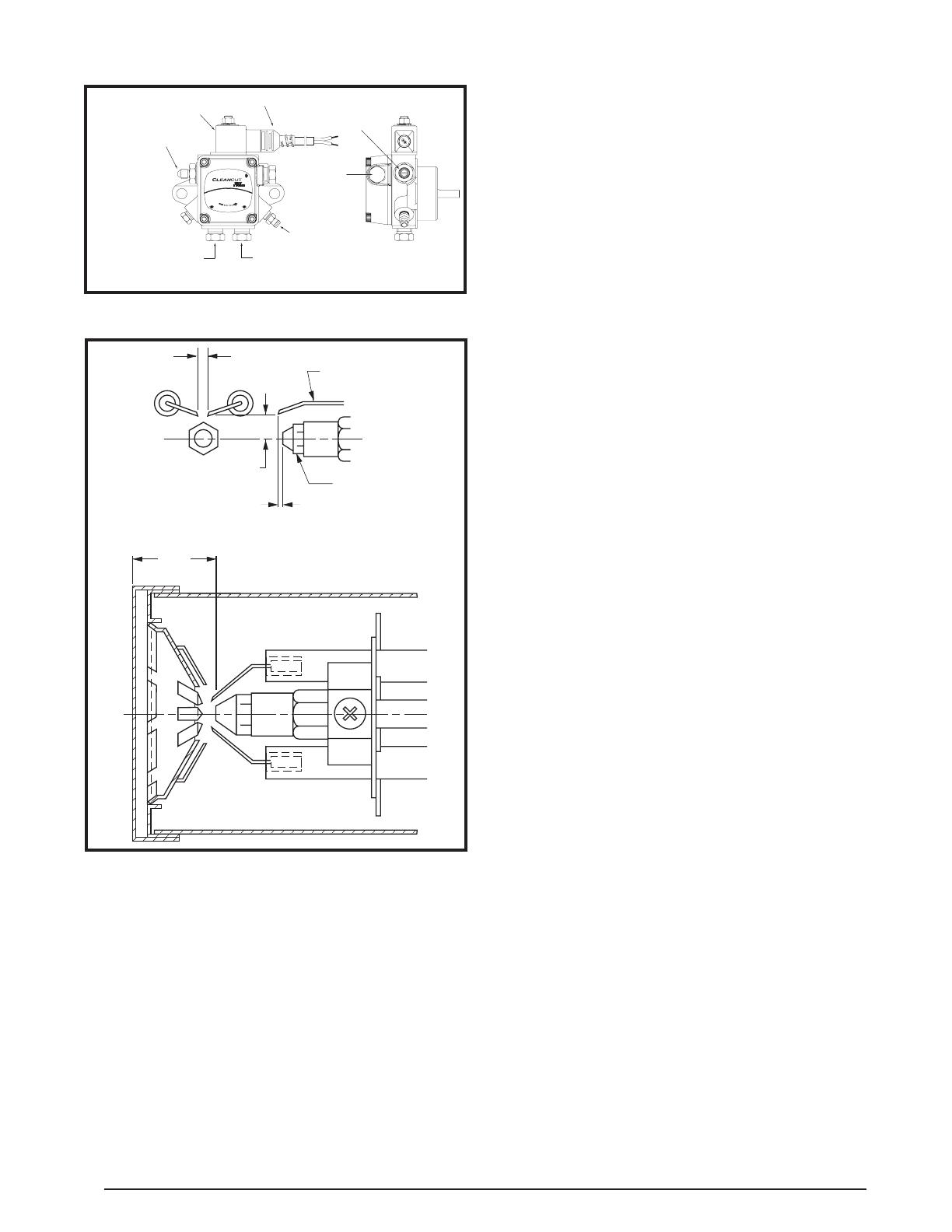
20
Figure15.OilPump
4 GPH 100-150 PSI 3450 RPM
3 GPH 150-200 PSI 3450 RPM
VALVE ON DELAY
NO. 2 & LIGHTER FUEL
USE ONLY WITH
INLET
BY-PASS
Exclusively for Beckett
Made by Suntec
INLET
NO. 2 FUEL
A2EA-6520
Becket
t
Nozzle Port
3/16 Flare Fitting
Bypass Solenoid Valve
Cordset
Inlet Port
1/4 NPTF
Bleed & Gauge Port
Pressure Adjustment
Screw
Inlet Port
1/4 NPTF
Return Port - Install 1/6” Bypass Pipe
Plug for 2-pipe System Only.
(Use 5/32” Allen Wrench)
Figure16.POOilBurnerElectrodeSettings
5/32” GAP
ELECTRODE
NOZZLE
0-1/16”
5/16” ABOVE CL
1 1/8”
OPERATING SEQUENCE
PG Gas Furnaces
1. ThethermostatcallsforheatbyenergizingtheWterminal
with24volts.
2. Thecombustionblowermotorenergizes.Afterthemotor
begins to rotate, the centrifugal switch (located in the
motorendcap)closes.
3. A30 secondpre-purgeperiod beginsandthe ignition
controlinitiatesaninternalsafetystartcheck.
4. Ifignitioncontrolpassesthesafetycheck,a15second
ignitorwarm-upperiodbegins.Duringthisperiod,the
ignitorwarmsuptoanignitiontemperature.
5. Thecontrolapplies24voltstothegasvalve.
6. Theignitorignitesthegas,andthepresenceofame
must be detected within a timed trial ignition period.
NOTE:Ifameisdetected,theignitorisde-energized
andthegasvalvewillremainopenuntilthecallforheat
from the thermostat is completed. If the ame is not
detected,thecontrolwillclosethegasvalveattheend
ofthetimedtrialignitionperiod.Thecontrolwillattempt
ignition2moretimesbeforelockingout.
7. The circulating air blower will energize when the
temperaturefanswitchcloses.
8. Whenthethermostatdemandforheatissatised,theW
terminalde-energizesthegasvalvecircuitandthegas
valvewillclose.
9. The circulating air blower will de-energize when the
temperaturefanswitchopens.
NOTES:
• Thecontrolwillclosethegasvalveiftheamesensor
doesnotdetectthepresenceofaame.Thecontrolwill
attempt to re-ignite the gas 2 times before locking out.
If lock-out occurs, the control can be reset by setting
the thermostat below room temperature for at least 45
seconds, and then returning it to the desired setting.
If adjusting the thermostat does not reset the ignition
control,turnoffallpowertotheappliancefor45seconds,
andthenturnitbackon.
• Ifthegascontrolhasbeenreplacedorserviced,lighting
maynotbesatisfactoryuntilairhasbeenpurgedfromthe
gaslineorthegasinputandcombustionairhavebeen
adjusted.
PO Oil Furnaces
Theprocesseslistedbelowareapplicableonlytofurnaces
equippedwithaBeckett7505Control.
1. Whenacallforheatisinitiated,thereisa2-6second
delaywhilethecontrolperformsasafestartcheck.
2. Theignitionandmotorturnonforthe15secondvalve
ondelay.Followingthedelay,thevalveenergzesanda
ameshouldestablishwithina15-secondlockouttime.
NOTES:
• Ifameisnotsensedwithinthe15-secondlockouttime,
thecontrolshutsdownonsafetylockout.Theresetbutton
onthecontrolmustbemanuallyreset.
• Ifcontrollocksout3times,thecontrolentersrestricted
lockout.ToresetBeckett7505: hold reset buttondown
for15secondsuntiltheredlightturnsoffandtheyellow
lightturnson.
3. Afterameisestablished,theignitionremainsONfor
10 seconds to ensure ame stability. It then turns off
(interruptedignition).
4. Thecirculatingairblowerwillenergizeandthetemperature
fanswitchwillclose.
/