
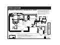
WIRING DIAGRAM
7112520
Air Handler with Factory Installed Heat (10kW)
Legend
Field Wiring
Factory Wiring:
Low Voltage
High Voltage
0812
GRAY
TERMINAL BLOCK
(for select models only)
CIRCUIT BREAKER
(circuit breaker models only)
CAP.
1
3
5
2
4
6
HEATER PLUG
RELAY
RELAY
Y
L2
L1
EAC
COOL
HEAT
W
G
R
C
R
C
L2
L1
-
7 6 5 4 3 2 1
240
24 V
208 COM
TRANSFORMER
R
C
BLACK
RED
WHITE
BROWN
BLACK
WHITE
RED
GRAY
ELEMENT
BLACK
GREY
BLACK
POWER
PLUG
LIMIT
RED
RED
RED
RED
RED
BLACK
RELAY
RELAY
ELEMENT
BLACK
BLACK
SUPPLY VOLTAGE
GRAY
ORANGE
BLUE
HARNESS
BROWN
GROUND
BLACK
RED
LOCATION OF
“T” CONNECTOR
MOTOR
4-SPEED
BLOWER
MOTOR
PLUG
6
5
4
3
2
1
1 = COM
2 = HIGH
3 = MED HIGH
4 = MED LOW
5 = LOW
6 = OPEN
NOTES:
1. The blower motor speed tap connection may not
be as shown. See the Installation Instructions.
2. Disconnect all power before servicing.
3. Transformer may have a dual voltage primary tap.
Match the tap position with the supply voltage
used.
4. If the internal wiring is replaced, use only 105°C
copper wire of the same gauge.
BLW DTC
BLACK
R
IF BOARD
EQUIPPED
WITH
BLWDTC
TERMINAL
Remarques
1. Le connecteur de vitesse du moteur du ventilateur peut différer de l’illustration.
Consultez les Instructions d’installation.
2. Débranchez toutes les sources d’alimentation avant l’entretien.
3. Le transformateur peut avoir un robinet principal à double tension. Agencez la
position du robinet au type de tension de l’installation.
4. Si le câblage interne est remplacé, utilisez seulement un fil de cuivre 105° C du
même gabarit.
-
 1
1

Ask a question and I''ll find the answer in the document
Finding information in a document is now easier with AI
in other languages
- français: Unbranded B6BV Information produit
Related papers
-
Broan B6BV Product information
-
Broan MB7BM Product information
-
Broan B6BV Product information
-
-
Gibson GB5BM Product information
-
Broan B6BW Product information
-
Broan H6HK, 8, 10 Kw 240V,1-Phase Electric Heater Kit Product information
-
-
-