Page is loading ...

002-096e-01.19
Instruction
Manual
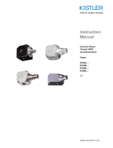
Shock Accelerometers
Type 8742A…
ä

Shock Accelerometer Page 1
002-096e-01.19
Instruction
Manual
Shock Accelerometers
Type 8742A…
CE
Kistler Instrument , 75 John Glenn Drive , Amherst, NY 14228-2171, Tel: 716-691-5100

Shock Accelerometer Page 2
002-096e-01.19
Table of Contents
1 Introduction ...................................................................................................................................... 3
2 Important Guidelines ........................................................................................................................ 3
2.1 For your safety ..................................................................................................................... 3
2.2 Precautions .......................................................................................................................... 4
2.3 Using This Manual ............................................................................................................... 4
2.4 Shock Accelerometer Types .................................................................................................. 5
2.5 Manual Nomenclature ......................................................................................................... 5
3 General Description .......................................................................................................................... 5
4 Technical Information, Functional Description .................................................................................. 6
4.1 Piezoelectric Measurement Concept ..................................................................................... 6
4.2 Shear Element Background ................................................................................................... 6
4.3 Low Impedance Output ....................................................................................................... 6
5 Installation ........................................................................................................................................ 7
5.1 General ................................................................................................................................ 7
5.2 Surface Preparation .............................................................................................................. 7
5.3 Stud Mounting ..................................................................................................................... 8
5.4 Securing Cables .................................................................................................................... 9
6 Operation ........................................................................................................................................ 10
6.1 Powering ........................................................................................................................... 10
6.1.1 Using “Built In” Power Sources .......................................................................................... 10
6.1.2 Kistler Couplers .................................................................................................................. 11
6.1.3 The Constant Current Power Supply/Coupler .................................................................... 11
6.1.4 Sensor Power-Up ............................................................................................................... 14
6.1.5 Overload Recovery ............................................................................................................ 14
6.1.6 Supply Voltage Effects ....................................................................................................... 14
6.2 Driving Long Cables ........................................................................................................... 15
6.3 Frequency Response Limits ................................................................................................ 17
6.3.1 Definition and Frequency Response Standards ................................................................... 17
6.3.2 High Frequency Limitations ................................................................................................ 17
6.3.3 Low Frequency Limitations - Transducer ............................................................................ 19
6.3.4 Low Frequency Limitations - Coupler and Readout Instrumentation................................... 21
7 Maintenance and Calibration .......................................................................................................... 22
7.1 General .............................................................................................................................. 22
7.2 Trouble Shooting ............................................................................................................... 22
7.3 Repairs ............................................................................................................................... 23
7.4 Cleaning ............................................................................................................................ 23
7.5 Calibration ......................................................................................................................... 23
8 Accessories ..................................................................................................................................... 24
8.1 Cables ................................................................................................................................ 24
9 Warranty ......................................................................................................................................... 24

Shock Accelerometer Page 3
002-096e-01.19
1 Foreword
Thank you for choosing a Kistler quality product characterized by
technical innovation, precision and long life.
Information in this document is subject to change without notice.
Kistler reserves the right to change or improve its products and make
changes in the content without obligation to notify any person or
organization of such changes or improvements.
© 2006 … 2019 Kistler Group. Kistler Group products are protected by
various intellectual property rights. For more details visit
www.kistler.com. The Kistler Group includes Kistler Holding AG and all
its subsidiaries in Europe, Asia, the Americas and Australia.
2 Introduction
By choosing Kistler shock accelerometers you have opted for an
instrument distinguished by precision, long life and technical
innovation. Please read these instructions carefully before installing
and operating these instruments.
Kistler offers a wide selection of measuring instruments and
comprehensive systems including:
* Sensors for force, pressure, acceleration, shock, vibration and strain.
* Associated signal conditioners and accessories.
* Piezoresistive pressure transducers and transmitters with associated
amplifiers.
Kistler can also provide entire systems for special purposes in the
automotive industry, plastics processing, and biomechanics. Our
general catalog provides information on Kistler products and services.
Detailed technical data sheets are available on most products offered.
Worldwide customer service is at your disposal should you have any
questions regarding this or other Kistler products. Information on
your specific application is also available from Kistler.
3 Important Guidelines
To ensure your personal safety, please observe the safety guidelines in
this section.
3.1 For your safety
* Carefully follow the installation information contained in section
5 of this manual.

Shock Accelerometer Page 4
002-096e-01.19
* Do not drop the instrument.
* Store in the case provided and in a clean, dry environment.
* Power the instrument in accordance with the instructions in
section 6 of this manual.
3.2 Precautions
Kistler sensors are thoroughly tested before leaving the factory. To
maintain safe and reliable operation, it is important to follow the
instructions herein.
* Do not mount accelerometers on high voltage surfaces.
* Keep cable clear of power lines and open machinery.
* Never operate or store the unit beyond the specified temperature
range.
* Do not exceed the maximum specified current.
* Never exceed the maximum specified voltage.
* Follow the instructions for mounting. Do not over tighten.
* When not in use, store the accelerometer in the container supplied.
Always store in a clean, dry area.
* Keep the connector clean and covered when not in use
• Exercise care during cable connection. Cable connector center pin
should align with the female receptacle on the accelerometer.
* Follow the recommendations in section 7.4
3.3 Using This Manual
Information contained herein includes a technical description,
installation and operating instructions, powering and considerations
for cable length. Section 8 contains a listing of mounting accessories
and cables available to assist with your measurement needs.
It is recommended that the entire manual be read prior to installation
and operation of shock accelerometers. The user who has prior
experience with Piezotron type accelerometers may want to confine
reading to particular sections of interest.
We have endeavored to arrange these instructions in a manner that
allows for easy location of topics of interest. Your Kistler
representative is also available to assist with any questions.
Information contained herein may be subject to change.

Shock Accelerometer Page 5
002-096e-01.19
3.4 Shock Accelerometer Types
This manual is applicable to all shock accelerometers listed on the title
page. Please see the product data sheets at the rear of this manual for
detailed specifications.
Figure 1: 8742A and 8741A…M1… Shock Accelerometer
3.5 Manual Nomenclature
Throughout this manual some special designations and nomenclature
are used for specific terms and concepts relating to shock sensors.
These are explained in Table 1.
Term: FS
Definition: Full Scale
Table 1: Manual Nomenclature
4 General Description
Kistler shock accelerometers are shear mode shock and vibration
measuring instruments. These units are intended for pyroshock
testing, metal-to-metal impact studies, drop testing, etc. A self-
generating piezoelectric sensing element is used in conjunction with
the built-in, internal circuit Piezotron* impedance converter. As with
most accelerometers, the sensitivity of this series is expressed in terms
of the ratio of the electrical output to applied acceleration (e.g.
mV/g). In the case of Piezotron devices such as used in this
accelerometer, the output is a low impedance voltage signal which is
proportional to the applied acceleration.
Being a low impedance device, no charge amplifier or special cabling is
required and transmission over long lines is possible with a minimum
of noise pick-up.

Shock Accelerometer Page 6
002-096e-01.19
5 Technical Information, Functional Description
5.1 Piezoelectric Measurement Concept
Piezoelectric accelerometers convert acceleration into an electric
charge. The charge derived by the accelerometer is proportional to
the force acting on the internal quartz (piezoelectric) element.
Accordingly, the mechanical variable (acceleration) is derived from a
force measurement. Shock accelerometers are specially tailored to
measure high acceleration from pyro shock levels to impact test
information.
5.2 Shear Element Background
The sensing assembly consists of a center post, quartz piezoelectric
crystals, seismic mass and a preload bolt. Since the unit is operated in
a shear arrangement it will sense motion perpendicular to the base.
When the accelerometer is attached to a vibrating structure, the mass
exerts a shear force on the quartz piezoelectric crystal. This applied
force causes the piezoelectric material to produce an electric charge.
Since force is mass times acceleration (from Newton's second law), the
charge produced is proportional to acceleration, since m is constant.
This is represented by:
The sensing element offers many advantages over previous shear and
compression mode designs. Because of shear construction the
accelerometer is insensitive to thermal transients, transverse (cross-
axis) motion and the effects of base strain.
5.3 Low Impedance Output
Contained within the accelerometer housing is a miniature electronic
circuit. This circuit converts the high impedance charge signal
generated by the piezoelectric element into a low impedance voltage
output signal with an output impedance typically below 100 ohms.
The integral impedance converter is powered by an external power
source (coupler) that uses a two-wire cable between the
accelerometer and coupler. The signal and power share a common
line. The coupler provides a constant current source to the
accelerometer and decouples the DC bias (see Section 6.1.3) from the
measuring instrument. The useful signal is seen as a varying voltage
over an 11 VDC (nominal) bias.
m
F
a

Shock Accelerometer Page 7
002-096e-01.19
Low impedance accelerometers are ideally suited for applications
where long or moving cables are required; in high humidity or other
contaminated atmospheres. They eliminate the problems associated
with high impedance output types by providing a low impedance
voltage signal with enhanced high frequency response. The
calibration factors for these accelerometers are given in mV/g.
Figure 2: Diagram of a Low Impedance Acceleration System
1. Low impedance (voltage output) accelerometer
2. Coaxial cable
3. Coupler (constant current supply) or dual mode amplifier
4. Cable
5. Readout or analysis equipment
6 Installation
6.1 General
For proper operation of shock accelerometers, care must be taken
during the installation process. Careful installation will result in
optimal high frequency response, accuracy and reliability.
6.2 Surface Preparation
A smooth, flat surface is necessary for both stud and adhesively
mounted accelerometers. If the surface is not completely flat, the
coupling between the accelerometer and the test article introduces
distortion into the measurement. A rough surface creates voids
between the mounting surfaces that reduce high frequency
transmissibility.
For optimum frequency response, the surface and hole preparation
should be according to the instructions in Table 3. The roughness
should not exceed 32 microinches (0.8 micrometers).

Shock Accelerometer Page 8
002-096e-01.19
6.3 Stud Mounting
The stud on both units is an integral part of the mounting base and
thus not removable. The following guidelines should be followed
when mounting shock accelerometers.
1. Drill and tap an adequate hole to ensure a flush mount of the
accelerometer. Make sure the stud does not bottom out. A
chamfer should be machined at the top of the mounting hole
to ensure that the base of the accelerometer makes full
contact with the mounting surface (See table 3).
2. Completely clean the surface prior to mounting.
3. Apply a thin coat of silicon grease to both the accelerometer
and mounting surface.
4. Always use the proper sockets and a torque wrench when
installing accelerometers. Tighten the accelerometer to the
torque specified on the individually supplied calibration
certificate or as specified in Table 2. Do Not Over Tighten.
in-lbs
Nm
Accelerometer Types
18 ±2
2 ±0.2
8742A
30 ±5
3.4 ±0.5
8742A….M1
Table 2: Recommended Mounting Torque
Figure 3: Dimensions that vary by designation.

Shock Accelerometer Page 9
002-096e-01.19
Outline dimensions used in mounting that vary by series designation
are shown in Figure 3. Type designations that include the letter E are
sized in metric units.
Surface Dia.
D
L1 inch [mm]
L2 inch [mm}
3/8” minimum
10-32 UNF
0.156 [4.0]
0.315 [8.0]
1/2” minimum
¼-28 UNF
0.22 [5.6]
0.42 [10.7]
Table 3: Mounting Surface Preparation
6.4 Securing Cables
Figures 4 and 5 show the correct and incorrect ways for installing
cables. Allow a sufficient radius to ensure a proper strain relief. The
actual radius will depend on the cables being used. It is recommended
that cables be secured to the accelerometer mounting surface to
minimize cable and connector fatigue failures. Secure cables with a
cable clamp.
Figure 4: Correct Cable Strain Relief

Shock Accelerometer Page 10
002-096e-01.19
Figure 5: Incorrect Cable Strain Relief
See Section 8.5 for information on cables available from Kistler.
7 Operation
Piezoelectric accelerometers are self generating transducers. While
the quartz piezoelectric sensor does not require an external power
source, it is necessary to provide power to the shock acceleometer’s
internal electronic impedance converter. This section is intended to
provide the user with the information necessary to ensure accurate
measurements with shock accelerometers. Topics to be covered
include powering, signal conditioning, frequency response and driving
long cables.
7.1 Powering
7.1.1 Using “Built In” Power Sources
Many FFT analyzers and vibration monitors are available with internal
accelerometer power supplies. Often identified as "Constant Current
Sources", these internal power supplies are generally compatible with
Kistler shock accelerometers.
Before using the built-in power source, compare the measurement
instrument current source specifications with the current and voltage
specifications of the shock accelerometer to be used. If the instrument
accelerometer power is within the range required by the specific shock
accelerometer there should be no problem with compatibility. If the
user plans to drive long cables (over 430 feet/130 m) the guidelines in
section 6.2 should be followed. The accelerometer low frequency
response may be affected by the input impedance of the measuring
instrument as discussed in Section 6.4.4.

Shock Accelerometer Page 11
002-096e-01.19
Caution: Many industrial monitors have adjustable current controls.
Exceeding the maximum current rating of any accelerometer may
cause permanent damage and void the warranty.
7.1.2 Kistler Couplers
Kistler offers a comprehensive line of power supply/couplers and dual
mode amplifiers. If the user is utilizing these instruments, they are
designed for compatibility with K-Shear accelerometers. The chart
below provides a listing of available power supply/couplers. Please
request data sheets on specific models.
Type
Description
5108A
Passive coupler. Customer provides power.
5114
Battery or line powered single channel coupler for hand held
or surface use.
5118B
Same as features as Type 5114 plus front panel adjustable
gain and filter provision.
5148
16-channel rack mountable AC powered coupler with unity
gain. LEDs indicate circuit integrity. Front panel BNC
output connectors.
5165A
Universal laboratory charge amplifier for dynamic measure-
ments; charge, Piezotron (IEPE) and voltage inputs; integra-
ted data acquisition; Ethernet interface; TEDS
Table 4: Coupler Table
7.1.3 The Constant Current Power Supply/Coupler
To better understand the purpose of the current source, a review of
the Piezotron* impedance converter is in order.
Figure 6 is a simplified schematic diagram of the shock accelerometer.
When excited, the quartz element produces a charge proportional to
the measurand. The resultant voltage(developed across Cr in Figure
6) is applied to the input of the internal impedance converter
(Electrometer Amplifier). The impedance converter will produce an
output voltage that follows the input faithfully.

Shock Accelerometer Page 12
002-096e-01.19
Figure 6: Simplified Diagram of the Shock Accelerometer
The source resistor (Rs), while located in the coupler, is a part of the
source follower circuit. In order for the Piezotron to provide enough
gain, Rs must have a high dynamic resistance while being able to
provide enough current (low DC resistance) as not to affect the high
frequency response of the system. Replacing Rs with a constant
current diode (Figure 7) provides a device with a high dynamic
resistance while allowing sufficient current to flow.
Figure 7: Schematic Diagram Of A Simple Coupler
Figure 7 shows a schematic of a simple power supply coupler for
shock accelerometers. DC power is supplied from a 24 volt source
such as a regulated power supply or batteries. One advantage of the
Piezotron system is the fact that a simple two wire coaxial cable is
used for both power and signal. Because the signal and power both
share the same line, it is necessary to include the capacitor C to
decouple (or block) the DC from the measurement instrument input.
Operating within the voltage range of 20...30 VDC assures a full
undistorted ±5 Volt output amplitude (See Figure 8). If the source
voltage is reduced, distortion and clipping of the signal will occur if
one attempts to use the full amplitude range of the accelerometer
Quartz
Element +
PIEZOTRON AMPLIFIER
To Coupler
CrRt
Electrometer Amplifier
Sensor

Shock Accelerometer Page 13
002-096e-01.19
(See Figure 9). The following equations are provided to calculate the
maximum full scale voltage available when operating with a reduced
voltage.
Maximum positive amplitude:
+
Fs
=
(
Es
1)
-
Eb
Maximum negative amplitude:
-
Fs
=
Eb -
2
Where:
Fs = Full scale output (peak)
ES = DC supply voltage (sometimes called compliance voltage)
Eb = bias voltage (from calibration certificate)
Figure 8: Output Signal When Operated With 28V Supply
Figure 9: Example of Output Distorting and Clipping when Supply
Voltage is Low
The shock accelerometer requires a minimum of 4mA of current to
enable the capturing of high frequency data.

Shock Accelerometer Page 14
002-096e-01.19
7.1.4 Sensor Power-Up
Figure 10: Behavior Of The Output Signal During Power-Up
When power is first applied to the sensor, (through an AC coupled
coupler) a voltage will appear at the output of the coupler (See Figure
10). As the coupling capacitor discharges, the DC output, from the
coupler will drop to zero Volts. This "settling time" is equal to 5 times
the time constant of the coupler employed. Allow time for the unit to
"settle" before making measurements.
7.1.5 Overload Recovery
Figure 11: Output Behavior During Overload and Recovery
Whenever the impedance converter is driven by a signal exceeding
the normal operating range, certain components will become non
operational. During this non operational state, the amplifier
components are protected from overload damage. The amount of
time required for recovery from an overload depends on several
factors. Important for overload recovery time is the size of the
overload. As with power-up, the time constant makes the biggest
contribution to the recovery time. Figure 11 illustrates a typical
overload and recovery sequence.
7.1.6 Supply Voltage Effects
Long-term fluctuations in the power supply level between 24 and 30
volts can be tolerated. The sensitivity shift caused by such deviation is
less than 0.05%/Volt. A normal noise level is maintained if the power
supply ripple is 25mV RMS or less. The polarity must be maintained
throughout the system since applying reversed polarity power may
cause damage to the accelerometer.

Shock Accelerometer Page 15
002-096e-01.19
7.2 Driving Long Cables
The voltage mode Piezotron circuit allows for long cable runs with low
noise susceptibility. Most laboratory instruments with built-in
accelerometer power provide current in the range of 2 to 4 mA. Most
Kistler couplers are set at the factory to provide 4mA of source
current. 4mA is a good compromise value for maximum frequency
response and high reliability.
Assuming a cable capacitance of 30pF/foot(98 pF/m), the full
frequency range of shock accelerometers can be realized (±5 Volt
output) up to a length of 430 feet (130 meters) with 4 mA of drive
current. Most Kistler cable types and common RG58 coaxial cable
have a rated capacitance of 30 pF/foot (98 pF/m). For most
laboratory applications this is quite adequate.
As cable length is increased the cable capacitance becomes significant,
thereby loading the Piezotron* impedance converter. If the current is
not sufficient to charge the cable at an adequate rate, high frequency
distortion will be experienced. The solution to this problem is to
increase the drive current
For the user's convenience a chart is provided (See Table 5). The
values given are based on a cable capacitance of 30 pF/foot (98
pF/m). The list of cables available from Kistler can be found in section
9.3. All cables in this section are 30pF/ft (98 pF/m). except for the
1331, 1635 and 1639 which are 20 pF per foot(65 pF/m).
Maximum
Frequency +/-
5%
Cable Length
Ft (meters)
Current (mA)
Required For
Output Signal
+/- 1 Volt
Current (mA)
Required For
Output Signal
+/- 5 Volts
10 kHz
1000 (300)
2
10
2000 (600)
4
18
9 kHz
1000 (300)
2
9
2000 (600)
4
17
8 kHz
1000 (300)
2
8
2000 (600)
3
15
7 kHz
1000 (300)
2
7
2000 (600)
3
14
6 kHz
1000 (300)
2
6
2000 (600)
3
12
5 kHz
1000 (300)
2
5
2000 (600)
2
10*
* Based on 30 pF/ foot (98 pF/meter)
Table 5: Current Requirements for Driving Long Cables

Shock Accelerometer Page 16
002-096e-01.19
The current requirements can be calculated using the following
equation:
Where:
Never use more current than required to make the desired
measurement. Never exceed the maximum current.
If a requirement calls for 1,000 feet (300m) of cable and the
maximum frequency of interest is only 5 kHz than the user should
select (From Table 5) 5 mA of current rather than the 10 mA required
for the full 10 kHz range. As current is increased, the noise produced
by the Piezotron circuit will also increase. The miniature Piezotron
amplifier will produce more heat as current is increased resulting in
reduced life and reliability.
The specified maximum temperature range (in the data sheet) is based
on 4 mA of supply current. It is necessary to degrade the maximum
operating temperature when operating under increased temperature
conditions. The graph in Figure 12 shows the approximate maximum
temperature vs. operating current.
Figure 12: Maximum PIEZOTRON Current as a Function of Operating
Temperature
Peak Volts,in Output =
Faradsin eCapacitanc =
Hzin Frequency =
Amperesin Current =
E
C
f
I
fCEI 2

Shock Accelerometer Page 17
002-096e-01.19
The equation for computing the maximum current for a specific
temperature is:
where:
I = Current in mA
t = Temperature is
7.3 Frequency Response Limits
All accelerometers have specified frequency limits which are a function
of the mechanical and electrical design. In order to better understand
the measurement process and limitations this section will describe
both the inherent limitations and limitations imposed by the
installation, operation and measurement-analysis instrumentation.
7.3.1 Definition and Frequency Response Standards
Frequency response is defined as a maximum specified amplitude
variation, from an established reference frequency, over a specified
bandwidth. Shock accelerometers are specified with maximum
variations of ±5% to ±10%. Kistler uses the industry standard
reference frequency of 100Hz.
Many users may be more familiar with the common frequency
response standard for electronic equipment which is generally *3dB.
In most mechanical applications an error of *3db (about *30%) does
not provide the required accuracy; thus, *5% (*10% in some cases) is
considered a more useful and accurate limit.
7.3.2 High Frequency Limitations
The inherent high frequency limit of an accelerometer is a function of
its mechanical characteristics Shock accelerometers can be
represented as an undamped single degree-of-freedom spring-mass
system. Accelerometers are modeled by the classical second order
differential equation whose solution is:
)150(16.0 maxmax tI
2
2
2
21
1
1
nn
b
o
ff
Qff
a
a

Shock Accelerometer Page 18
002-096e-01.19
Where:
Quartz accelerometers have a Q of approximately 10 to 40 and
therefore the phase angle can be written as:
Using the basic equation for resonance one can better understand the
basic accelerometer mechanical system and the affect on high
frequency response.
The spring constant (k) is determined by the stiffness of the quartz
crystal and preload stud. The mass (m) is the supported part of the
accelerometer structure. This spring-mass system is the basic
component that converts the input forces into acceleration. As with
any single degree-of-freedom system, a resonance condition will occur
(per the above equation) which causes the sensitivity to increase with
frequency.
It is desirable to have a uniform frequency response over the specified
frequency range. As can be seen, (Figure 13), the sensitivity greatly
increases when approaching resonance. About a 5% amplitude rise
can be expected at 9/40 of the resonant frequency. It is possible to
operate above the maximum specified frequency by applying the
appropriate correction factors, or filtering to compensate for the
resonant rise in response.
resonanceat increase amplitude offactor =
1on accelerati reference of base mounting =
onacceleratioutput =
(Hz) curve theofpoint given any at frequency =
(Hz)frequency (resonant) natural undamped =
Q
fn
f
a
a
f
f
b
o
n
system freedom of degree single a of
5
260
(deg) Lag Phase
nn ff
for
ff
Q
m
k
fn
2
1

Shock Accelerometer Page 19
002-096e-01.19
Figure 13: Typical Frequency Response of a Piezoelectric
Accelerometer
Section 5 provides important information regarding mounting. It is
important that these instructions are followed to ensure optimal
transmissibility at high frequencies. Mounting to rough surfaces,
using soft adhesives and magnetic mounts will limit the high
frequency range to some value lower than the specified frequency
range.
7.3.3 Low Frequency Limitations - Transducer
The low frequency response of accelerometers is an electrical
limitation. The design of shock accelerometers is such that low
frequency drift caused by temperature variations is virtually
eliminated.
The shock accelerometer sensing element is a self-generating device
which produces a voltage proportional to the applied acceleration.
The piezoelectric output voltage is applied to the high impedance
input of the FET where it is converted to a low impedance output
voltage signal.
At low frequencies the amplifier input circuit acts as a single order
high-pass filter (See Figure 6) whose amplitude and phase are:
in
oin
in
o
VVV
f
f
f
V
V
80
)(2 1
tan arc = (deg) lead phase
)](2[1
)(2
2
/

