Page is loading ...

WARNING
This product is part of a personal fall arrest, work positioning, or rescue system. The manufacturer’s instructions must be provided to
users of this equipment. The user must follow the manufacturer’s instructions for each component of the system. The user must read and
understand these instructions before using this equipment. Manufacturer’s instructions must be followed for proper use and maintenance
of this equipment. Alterations to this product, misuse of this product, or failure to follow instructions may result in serious injury or death.
IMPORTANT
Questions regarding the use, care, or suitability of this equipment for your application? Contact Safewaze.
IMPORTANT
Record initial usE of product on Page 2, and Page 11. Competent Person inspections are required to be documented in the Inspection
Log Table on Page 11.
019-11000
Tripod
220-00012
User Manual
V2.0 2022 Copyright Safewaze

TABLE OF CONTENTS
1 INTRODUCTION .................................................................................... 3
2 APPLICABLE SAFETY STANDARDS .................................................... 3
3 WORKER CLASSIFICATIONS ............................................................... 3
4 PRODUCT SPECIFIC APPLICATIONS .................................................. 4
5 LIMITATIONS .......................................................................................... 4
6 COMPATIBILITY OF CONNECTIONS ................................................... 5
7 MAKING CONNECTIONS ...................................................................... 6
8 COMPONENTS AND SPECIFICATIONS ............................................... 7
9 INSTALLATION AND USE .....................................................................8-9
10 INSPECTION ......................................................................................... 10
11 INSPECTION LOG ................................................................................ 11
12 SAFETY INFORMATION .....................................................................12-13
13 LABELS.................................................................................................. 13
Do not throw away these instructions!
Read and understand these instructions before using equipment!
User Information
Date of First Use:
Serial#:
Trainer:
User:
User Manual
V2.0 2022 Copyright Safewaze
Page 2

INTRODUCTION
Thank you for purchasing the Safewaze 019-11000 Conned Space System Tripod. This
manual must be read and understood in its entirety, and used as part of an employee training
program as required by OSHA or any applicable state agency.
This manual and any other instructional material must be available to the user of the equipment.
The user must understand how to safely and eectively use the 019-11000, and all fall protection
eqipment used in conjuction with the 019-11000.
The 019-11000 Tripod is designed primarily for workers entering and working in conned space
environments. OSHA denes conned space as any space with limited openings for entry and exit,
is large enough for a worker to enter bodily and perform work, and is not designed for continuous
worker occupancy.
Conned spaces include but are not limited to, utility manholes, silos, undergound utility vaults,
storage containers, pits, and pipelines.
The 019-11000 Tripod serves as the support element for entry/egress into conned spaces, and also
the rescue/evacuation of workers if necessary. It can also provide anchorage for fall protection, work
postioning, and personnel riding systems.
APPLICABLE SAFETY STANDARDS
When used according to instructions, this product meets or exceeds ANSI Z117.1-2009, Z359.14,
ANSI A10.32-2012, OSHA 1926.502, 1910.140, & 1926.21. Applicable standards and regulations
depend on the type of work being done, and also might include state-specic regulations. Refer to
local, state, and federal (OSHA) requirements for additional information concerning the governing of
occupational safety regarding Personal Fall Arrest Systems (PFAS).
Worker Classifications
Understand the denitions of those who work in proximity of or may be
exposed to fall hazards.
Qualied Person: A person with an accredidated degree or certication, and with extensive
experience or sucient professional standing, who is considered procient in planning and reviewing
the conformity of fall protection and rescue systems.
Competent Person: A highly trained and experienced person who is assigned by the employer to
be responsible for all elements of a fall safety program, including, but not limited to, its regulation,
management, and application. A person who is procient in identifying existing and predictable
hazards, and who has the authority to stop work in order to eliminate hazards.
Authorized Person: A person who is assigned by their employer to work around or be subject to
potential or existing fall hazards.
It is the responsibility of a Qualied or Competent person to supervise the job site and
ensure safety regulations are complied with.
User Manual
V2.0 2022 Copyright Safewaze
Page 3

Product Specific Applications
Rescue / Conned Space: The 019-11000 Conned Space System Tripod may be used in both
Conned Space and Rescue applications. Rescue systems function to safely remove a worker from
a conned space environment or after exposed to a fall. There are various congurations of rescue
systems depending on the type of rescue required. Structure must withstand loads applied in the
directions permitted by the system of at least 3,000 lbs. No free fall is permitted. Applicable D-rings
are dorsal, chest, and shoulder.
Lanyard Length
(6’ Total)
Deceleration
distance (4’ total)
Height of harness
dorsal D-ring from
worker’s feet
(6’ total)
Safety factor
(2’ total)
Required
distance
from
Anchorage
(18’ total)
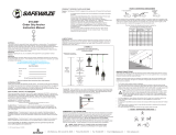
Fall Clearance: There must be sucient clearance below the anchorage connector to arrest a fall
before the user strikes the ground or an obstruction. When calculating fall clearance, account for a
MINIMUM 2’ safety factor, deceleration distance, user height, length of lanyard/SRL, and all other
applicable factors. (See Figure 1)
Limitations
Fall Clearance Diagram
***Diagram shown is an example
fall clearance calculation ONLY. For all applications: worker weight capacity range
(including all clothing, tools, and equipment) is 130-310 lbs
FIGURE 1
User Manual
V2.0 2022 Copyright Safewaze
Page 4

Swing Falls: Prior to installation or use, make considerations for eliminating or minimizing all swing
fall hazards. Swing falls occur when the anchor is not directly above the location where a fall occurs.
Always work as close to in line with the anchor point as possible. Swing falls signicantly increase
the likelihood of serious injury or death in the even of a fall. (See Figure 2)
A
FALL-ARREST
S
W
I
N
G
F
A
L
L
COMPATIBILITY OF CONNECTORS
Connectors are compatible with connecting elements when they have been designed to work together
in such a way that their sizes and shapes do not cause their gate mechanisms to inadvertently
open regardless of how they become oriented. Connectors (hooks, carabiners, and D-rings) must
be capable of supporting at least 5,000 lbs. (22.2 kN). Connectors must be compatible with the
anchorage or other system components (see Figure 4). Do not use equipment that is not compatible.
Non- compatible connectors may unintentionally disengage (see Figure 3). Connectors must be
compatible in size, shape, and strength. Self-locking snap hooks and carabiners are required by
ANSI Z359 and OSHA guidelines. Contact Safewaze if you have any questions about compatibility.
FIGURE 3 - UNINTENTIONAL DISENGAGEMENT
Using a connector that is undersized or irregular in shape (1) to connect a snap hook or carabiner
could allow the connector to force open the gate of the snap hook or carabiner. When force is applied,
the gate of the hook or carabiner presses against the non-compliant part (2) and forces open the gate
(3). This allows the snap hook or carabiner to disengage (4) from the connection point.
3 - gate opens
2 - gate presses
against
non-complaint
part
4 - and parts disengage.1 - Non-compliant part
NOTE: SOME SPECIALITY CONNECTORS HAVE ADDITIONAL REQUIREMENTS.
CONTACT SAFEWAZE WITH QUESTIONS.
FIGURE 2
User Manual
V2.0 2022 Copyright Safewaze
Page 5

User Manual
V2.0 2022 Copyright Safewaze
Page 6
FIGURE 4 - INAPPROPRIATE CONNECTIONS
MAKING CONNECTIONS
Snap hooks and carabiners used with this equipment must be double locking and/or twist lock.
Ensure all connections are compatible in size, shape and strength. Do not use equipment that is not
compatible. Ensure all connectors are fully closed and locked.
Safewaze connectors (snap hooks and carabiners) are designed to be used only as specied in each
product’s user’s instructions. See gure 4 for examples of inappropriate connections. Do not connect
snap hooks and carabiners:
• To a D-ring to which another connector is attached.
• In a manner that would result in a load on the gate (with the exception of tie back hooks).
• NOTE: Large snap hooks must not be connected to objects which will result in a load on the
gate if the hook twists or rotates, unless the snap hook complies with ANSI Z359.1-2007 or ANSI
Z359.12 and is equipped with a 3,600 lb (16 kN) gate. Check the marking on your snap hook to
verify its compatibility.
NOTE: Large throat snap hooks must not be connected to standard size D-rings or similar objects which
will result in a load on the gate if the hook or D-ring twists or rotates, unless the snap hook complies with
ANSI Z359.1-2007 or ANSI Z359.12 and is equipped with a 3,600 lb (16 kN) gate. Check the marking on
your snap hook to verify that it is appropriate for your application.
• In a false engagement, where features that protrude from the snap hook or carabiner catch on the anchor, and
without visual conrmation seems to be fully engaged to the anchor point.
• To each other.
• By wrapping the web lifeline around an anchor and securing to lifeline except as allowed for Tie Back models (see
section 4.5).
• To any object which is shaped or sized in a way that the snap hook or carabiner will not close and lock, or that
roll-out could occur.
• In a manner that does not allow the connector to align properly while under load.

Components and Specifications
Tripod Safety Chain
Pulleys
019-11000
Tripod
Adjustable Legs
Captive Eye
Anchor Points
Interior Headroom 81 in (2057.4 mm)
Distance Between Feet 61 in (1549.4 mm)
Max Diameter Hole 44 in (1117.6 mm)
Working Load 350 lbs (158.76 kg)
Static Strength 5,000 lbs min. static strength
Overall Height 84 in (2133.6 mm)
Storage Length 65 in (1651 mm)
Outside Head Diameter 17 in (431.8 mm)
Leg Adjustment Increments 6 in (152.4 mm)
Weight 50 lbs (22.68 kg)
User Manual
V2.0 2022 Copyright Safewaze
Page 7

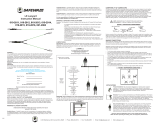
Installation and Use
Step 1: Remove tripod from tripod storage/carrying bag.
Step 2: Tripod must be mounted on a stable level surface for each leg, when positioned over
opening with a Maximum Installation Diameter of 44 inches. Lift tripod to upright position. Press
locking pin above each leg in the tripod head and pull leg away from center point until locking pin
locks into place. Repeat with the ramaining legs. (See Image 1)
Step 3: Remove Locking Pins above foot of tripod legs and extend legs to desired height. Re-insert
locking pin at desired height, (See Image 2) and connect safety chains to bottom of tripod legs.
Remove excess slack in the safety chain by adjusting the position of the twist link.
Step 4: This step decribes actions to be taken if attaching / installing a Safewaze 3-Way Retractable,
Material Winch, or Personnel Winch onto the tripod via mounting to one of the tripod legs. This step
must be performed in order to ensure proper routing of component cables through the top of the
tripod. Remove Cotter Pins, Pulley Housing, and pulleys from the top of tripod. (See Image 3 & 4)
Image 1
Image 2
Image 3 Image 4
Locking Pin
Locking Pin
Cotter Pin
Pulley
Pulley Housing Top of Tripod
(With pulleys removed)
User Manual
V2.0 2022 Copyright Safewaze
Page 8

Step 5: If a Safewaze 3-Way Retractable, Material Winch, or Personnel Winch was installed onto
the Tripod (See specic component instructions for proper tripod mounting), the cable constiuent of
the component must be routed over and through the top of the tripod. Pull out the required amount of
cable from the component to drop through the head assembly of the tripod. Drape the cable over the
top of the tripod and slide the snap hook down through the opening in the top of the tripod where the
pulley (previously removed in Step 4) is normally seated. (See Image 5) Re-install the pulley
assemblies removed in Step 4. Ensure the component cable(s) are routed over the top of the
pulley(s). (See Image 6) The 019-11000 Tripod and subcomponents are now ready for use.
Image 6
Pulley
Pulley
3-Way Cable
Material Winch
Cable
Image 5
User Manual
V2.0 2022 Copyright Safewaze
Page 9

User Manual
V2.0 2022 Copyright Safewaze
Page 10
Inspection
USER MUST KEEP INSTRUCTIONS AVAILABLE FOR REFERENCE. Record Date of First Use.
Prior to each use, inspect the 019-11000 for possible deciencies including, but not limited to,
corrosion, deformation, pits, burrs, rough surfaces, sharp edges, cracking, rust, paint buildup,
excessive heating, alteration, and missing or illegible labels. User MUST IMMEDIATELY remove the
019-11000 from service is defects or damage are found, or if exposed to forces of fall arrest.
Inspect work area to ensure that location is free of any damage including, but not limited to,
debris, cracking, rot, decay, structural deterioration, rust, and free from any hazardous materials.
User must conrm that work area to be utilized will support the application specic loads as
referenced within this instruction manual. Work area MUST be stable.
At least annually, a Competent Person other than the user must inspect the 019-11000.
Competent Person inspections must be recorded in the inspection table included in this manual as
well as the inspection table labels on each product individually. The Competent Person must place
his/her initials in the block which corresponds with the month and year that the inspection is
performed. All individual labels on equipment will be initialed in the same manner.
While conducting inspections, the Competent Person must consider all applications and hazards that
the equipment may have been subjected to while in use.
Prior to each use, the user must inspect and verify that each individual component of the
019-11000 is safe for use.
019-11000 Aluminum Tripod inspection:
1. Inspect for bent or deformed tripod legs.
2. Inspect that all locking pins for tripod legs are present and functional.
3. Inspect triopod pulley assembly for any missing for damaged components including,
pulleys, cotter pins, and pulley housings.
4. Ensure that tripod feet are clear of any debris and undamaged so that they can pivot
freely.
5. Inspect tripod chain for any kinks, broken links, corrosion, chemical exposure or any other
damage.
6. Inspect entire unit for any bends, cracks, corrosion, chemical exposure, or any factor that
may eect integrity of the tripod unit.

User Manual
V2.0 2022 Copyright Safewaze
Page 11
Inspection Log
Product lifetime is indenite as long as it passes pre-use and Competent Person inspections. User
must inspect prior to each use. Competent Person other than the user must complete formal
inspection at least annually. Competent person to inspect and initial table below:
If equipment fails inspection
IMMEDIATELY REMOVE FROM SERVICE
Date of First Use:_______________
Date Inspection Items
Noted
Corrective Action Initials

User Manual
V2.0 2022 Copyright Safewaze
Page 12
Safety Information
Failure to understand and comply with safety regulations may result in serious
injury or death. Regulations included herein are not all-inclusive, are for
reference only, and are not intended to replace a Competent Person’s
judgement or knowledge of federal or state standards.
Do not alter or misuse equipment.
Workplace conditions, including, but not limited to, ame, corrosive chemicals, electrical shock, sharp
objects, machinery, abrasive substances, weather conditions, and uneven surfaces, must be
assessed by a Competent Person before fall protection equipment is selected.
The inspection of the workplace must anticipate where workers will be performing their duties, the
routes they will take to reach their work, and the potential and existing fall hazards they may be
exposed to. Fall protection equipment must be chosen by a Competent Person. Selections must
account for all potential hazardous workplace conditions. All fall protection equipment should be
purchased in new and unused condition.
Fall protection systems must be selected and installed under the supervision of a Competent Person,
and used in a compliant manner. Fall protection systems must be designed in a manner compliant
with all federal, state, and safety regulations. Forces applied to anchors must be calculated by a
Competent Person.
Harnesses and connectors selected must be compliant with manufacturer’s instructions, and must be
of compatible size and conguration. Snap hooks, carabiners, and other connectors must be
selected and applied in a compatible fashion. All risk of disengagement must be eliminated. All snap
hooks and carabiners must be self-locking and self-closing, and must never be connected to each
other.
A pre-planned rescue procedure is required in the event a fall occurs. The rescue plan must be
project-specic. The rescue plan must allow for employees to rescue themselves, or provide an
alternative means for their prompt rescue. Store rescue equipment in an easily accessible and clearly
marked area.
Training of Authorized Persons to correctly erect, inspect, disassemble, maintain, store, and use
equipment must be provided by a Competent Person. Training must include the ability to recognize
fall hazards, minimize the likelihood of fall hazards, and the correct use of personal fall arrest
systems.
NEVER use fall protection equipment of any kind to hang, lift, support, or hoist tools or equipment,
unless explicitly certied for such use.
Equipment subjected to forces of fall arrest must immediately be removed from use.
WARNING

User Manual
V2.0 2022 Copyright Safewaze
Page 13
Age, tness, and health conditions can seriously aect the worker should a fall occur. Consult a
doctor if there is any reason to doubt a user’s ability to withstand and safely absorb fall arrest forces
or perform set-up of equipment. Pregnant women and minors must not use this equipment.
Physical harm may still occur even if fall safety equipment functions correctly. Sustained post-fall
suspension may result in serious injury or death. Use trauma relief straps to reduce the eects of
suspension trauma.
Safety Information (cont)
Labels
225 Wilshire Ave SW,Concord, NC 28025
(800) 230-0319
www.safewaze.com
019-11000
019-11001
019-11002
019-11003
019-11004
MATERIALS: Aluminum, Zinc Plated Steel
CAPACITY: 130-310 lbs. (59-140 kg)
WORKING LOAD
350 lbs. (159 kg) maximum
MEETS
ANSI Z117.1, Z359.14, A10.32
OSHA 1926.502, 1910.140 & 1926.21
01161a
CONFINED SPACE TRIPOD
1 2 3 4 5
Inspection
Year
021-11026
WARNING: User must read and
understand all instructions provided
with this product at time of
shipment prior to use. Misuse of
this product or failure to follow
instructions may result in serious
injury or death. Make only
compatible connections.
USE: Tripod must be used on
generally level and solid footing.
Tripod leg chains should be
adjusted to remove slack to avoid
tripping hazard. Load must be
maintained inside chain perimeter
to prevent tipping. Do not allow
components of any fall arrest,
rescue, or personal suspension
system to contact sharp edges or
abrasive surfaces during use. Avoid
chemical, thermal, and/or electrical
hazards.
INSPECTION: Tripod must be
inspected prior to each use. This
product must be inspected by a
competent person at least every 6
months or more frequently in harsh
environments. Do not use if
inspection reveals damaged
components or defective condition
01161b

WARRANTY
Safewaze
225 Wilshire Ave SW
Concord, NC 28025
USA
PHONE: 1-800-230-0319
FAX: 1-704-262-9051
EMAIL: [email protected]
Web: safewaze.com
User Manual
V2.0 2022 Copyright Safewaze
Page 14

Manual del usuario
V2.0 2020 Copyright Safewaze
ADVERTENCIA
Este producto forma parte de un sistema personal de parada de caídas, posicionamiento de trabajo o rescate. Las
instrucciones del fabricante se le deben entregar al usuario de este equipo. El usuario debe seguir las instrucciones del
fabricante de cada componente del sistema. Antes de usar este equipo, el usuario debe leer y entender estas instrucciones.
El usuario debe seguir las instrucciones del fabricante para usar y mantener correctamente este equipo. Alterar o usar
incorrectamente este equipo, o no seguir las instrucciones, puede causar lesiones graves o muerte.
IMPORTANTE
Si tiene dudas sobre el uso, cuidado o idoneidad de este equipo para sus propósitos, comuníquese con Safewaze.
IMPORTANTE
Registre el uso inicial del producto en la página 2 y en la página 11. Las inspecciones de la persona competente se deben
documentar en la tabla del registro de inspecciones de la página 11.
019-11000
Trípode
220-00012

Manual del usuario
V2.0 2020 Copyright Safewaze Pág. 2
ÍNDICE DE MATERIAS
1. INTRODUCCIÓN............................................................................... 3
2. NORMAS DE SEGURIDAD APLICABLES ....................................... 3
3. DENOMINACIONES DE USUARIOS .............................................. .3
4. CONFIGURACIONES ESPECÍFICAS DEL PRODUCTO ................ 4
5. LIMITACIONES ................................................................................. 4
6. COMPATIBILIDAD DE CONEXIONES ............................................. 5
7. FORMACIÓN DE CONEXIONES ..................................................... 6
8. COMPONENTES Y ESPECIFICACIONES ...................................... 7
9. INSTALACIÓN Y USO ................................................................... 8-9
10. INSPECCIÓN .................................................................................. 10
11. REGISTRO DE INSPECCIONES ................................................... 11
12. INFORMACIÓN DE SEGURIDAD .............................................12-13
13. ETIQUETAS .................................................................................... 13
Datos del usuario
Fecha de la primera vez que usó el equipo:
Nro. de serie:
Capacitador:
Usuario:
¡No deseche estas instrucciones!
Antes de usar este equipo, el usuario debe leer y entender estas instrucciones.

Manual del usuario
V2.0 2020 Copyright Safewaze Pág. 3
Introducción
Gracias por comprar este trípode de sistema de espacios reducidos 019-11000 de Safewaze. El usuario debe
leer y entender todo este manual, que debe formar parte de un programa de capacitación del usuario según lo
requerido por la OSHA o las agencias estatales correspondientes.
Este manual y todo otro material de enseñanza deben estar siempre a disposición del usuario del equipo. El
usuario debe entender cómo usar segura y efectivamente el 019-11000 y todo el equipo de protección contra
caídas que se usa con el 019-11000.
El trípode 019-11000 ha sido diseñado principalmente para usuarios que deben entrar a trabajar en espacios
reducidos. La OSHA define espacio reducido de la siguiente manera: espacio con aberturas de entrada y
salida restringida de tamaño suficiente para que un trabajador entre físicamente a hacer una tarea pero no
para ocuparlo continuamente.
Los espacios reducidos pueden ser, entre otros, silos, fosos, tuberías, contenedores de almacenamiento,
registros de servicios públicos, bóvedas subterráneas de servicios públicos, etc.
El trípode 019-11000 es una estructura de soporte para entrar y salir de espacios reducidos, y también para
rescatar y evacuar al usuario, si es necesario. El trípode 019-11000 también puede funcionar como dispositivo
de anclaje de protección contra caídas, posicionamiento de trabajo y transporte de personal.
NORMAS DE SEGURIDAD APLICABLES
Cuando se usa conforme a las instrucciones, este producto satisface o supera las normas Z117.1-2009,
Z359.14 y A10.32-2012 del ANSI y los reglamentos 1926.502, 1910.140 y 1926.21 de la OSHA. Las normas y
los reglamentos aplicables dependen del tipo de trabajo y pueden incluir reglamentos estatales específicos.
Consulte los requisitos locales, estatales y federales (OSHA) para ver más información sobre los reglamentos
de seguridad ocupacional que rigen los sistemas personales de parada de caídas.
Denominaciones de usuarios
Entienda las denominaciones de las personas que se exponen a caídas o
trabajan cerca de estructuras que implican riesgo de caída.
Persona calificada: Persona con certificación o título homologado, y amplia experiencia o suficiente prestigio
profesional, que se considera competente en la planificación y revisión de la conformidad de los sistemas de
rescate y protección contra caídas.
Persona competente: Persona altamente capacitada y experimentada que el empleador responsabiliza de
todos los elementos de un programa de seguridad contra caídas, tales como, entre otros, regulación,
administración y aplicación. Esta persona es competente en cuanto a la identificación de peligros conocidos y
predecibles, y está autorizada a suspender el trabajo para eliminar los peligros.
Persona autorizada: Persona nombrada por el empleador para exponerse a riesgos de caídas conocidos o
posibles, o trabajar cerca de lugares en que existen tales riesgos.
Las personas calificadas o competentes son responsables de supervisar el lugar de trabajo y
garantizar que se cumplan las normas de seguridad.

Manual del usuario
V2.0 2020 Copyright Safewaze Pág. 4
Configuraciones específicas del producto
Rescate y espacio reducido: El trípode de espacios reducidos 019-11000 se puede usar en configuraciones
de rescate y espacio reducido. Los sistemas de rescate permiten recuperar con seguridad a un usuario
atrapado en un espacio reducido o suspendido en el aire después de una caída. La configuración del sistema
de rescate depende del tipo de rescate. La estructura debe soportar cargas de al menos 3,000 lbs. aplicadas
en las direcciones permitidas por el sistema. No se permite la caída libre. Los puntos de fijación permitidos del
arnés son el anillo dorsal en D, el anillo pectoral en D y los anillos en D de los hombros.
Limitaciones
Altura de caída: Debe haber suficiente espacio debajo del conector de anclaje para parar una caída antes de
que el usuario llegue al suelo o se golpee contra algo. Cuando calcule la altura de caída, considere la
distancia de desaceleración, la estatura del usuario, la longitud del cordón o la SRL, un factor de seguridad de
2 pies como MÍNIMO, y todo otro factor aplicable (Figura 1).
FIGURA 1
Diagrama de altura de caída
*** El diagrama que se muestra es SOLO
un ejemplo de cálculo de altura de caída.
Longitud del
cordón (6 pies)
Distancia
requerida desde
el anclaje
(18 pies en total)
Distancia de
desaceleración (4 pies)
Factor de seguridad
(2 pies)
Altura del anillo dorsal en
D del arnés desde los pies
del usuario (6 pies)
En todas las configuraciones, el intervalo
de capacidad es de 130 a 310 lbs. por usuario
(incluyendo herramientas, ropa y equipo).

Manual del usuario
V2.0 2020 Copyright Safewaze Pág. 5
Caídas pendulares: Antes de instalar o usar el sistema, elimine o minimice los riesgos de caída pendular,
que se presentan cuando el punto de anclaje no está directamente encima del punto de caída. Trabaje
siempre lo más cerca posible del punto de anclaje. Las caídas pendulares aumentan significativamente la
probabilidad de lesiones graves o muerte (Figura 2).
FIGURA 2
COMPATIBILIDAD DE CONECTORES
Los conectores son compatibles con los elementos que se les conectan cuando han sido diseñados para
funcionar juntos de manera que su tamaño y su forma no causen la apertura imprevista de los cierres,
independientemente de su orientación. Los conectores (ganchos, mosquetones y anillos en D) deben tener al
menos 5,000 lbs. (22.2 kN) de capacidad. Los conectores deben ser compatibles con el anclaje y los otros
componentes del sistema (Figura 4). No use equipo incompatible. Los conectores incompatibles pueden
desengancharse de improviso (Figura 3). Los conectores deben ser compatibles en cuanto a tamaño, forma y
capacidad. La norma ANSI Z359 y las directrices de la OSHA exigen ganchos de presión y mosquetones de
bloqueo automático. Comuníquese con Safewaze si tiene preguntas sobre compatibilidad.
NOTA: ALGUNOS CONECTORES ESPECIALIZADOS TIENEN REQUISITOS
ADICIONALES. COMUNÍQUESE CON SAFEWAZE SI TIENE PREGUNTAS.
FIGURA 3 - DESENGANCHE NO INTENCIONAL
Conectar un conector demasiado pequeño o de forma irregular (1) a un mosquetón o un gancho de presión
puede permitir que el conector abra el cierre del mosquetón o gancho de presión. Cuando se ejerce fuerza, el
cierre del mosquetón o gancho se apoya en la pieza incompatible (2) y se abre (3). Esto permite que el
mosquetón o gancho de presión se desenganche (4).
2 - El cierre se apoya en
la pieza incompatible.
4 - Las piezas se desenganchan.
3 - El cierre se abre.
1 - Pieza incompatible

Manual del usuario
V2.0 2020 Copyright Safewaze Pág. 6
FORMACIÓN DE CONEXIONES
Los mosquetones y ganchos de presión de este equipo deben tener cierre de bloqueo doble y/o cierre
giratorio. Todas las conexiones deben ser compatibles en cuanto a tamaño, forma y capacidad. No use equipo
incompatible. Todos los conectores deben estar completamente cerrados y bloqueados.
Los conectores de Safewaze (mosquetones y ganchos de presión) deben usarse solo como se especifica en
las instrucciones de cada producto. En la Figura 4 hay ejemplos de conexiones incorrectas. No conecte
mosquetones o ganchos de presión…
A un anillo en D al cual ya esté conectado otro conector.
De una manera que ejerza fuerza sobre el cierre (excepto en caso de ganchos de sujeción).
NOTA: No se deben conectar ganchos de presión grandes a objetos que se apoyarían en el cierre si el
gancho se torciera o girara, a menos que el gancho de presión cumpla con la norma ANSI Z359.1-2007
o ANSI Z359.12 y tenga un cierre de 3,600 lbs. (16 kN) de capacidad. Vea el marcado del gancho de
presión para verificar su compatibilidad.
NOTA: Los ganchos de presión de gran apertura no se deben conectar a anillos en D de tamaño
estándar u objetos similares que se apoyarían en el cierre si el gancho o el anillo en D se torciera o
girara, a menos que el gancho de presión cumpla con la norma ANSI Z359.1-2007 o ANSI Z359.12 y
tenga un cierre de 3,600 lbs. (16 kN) de capacidad. Vea el marcado del gancho de presión para verificar
su compatibilidad.
Con enganche falso, que se produce cuando las partes sobresalientes del mosquetón o gancho de
presión se enganchan en el ancla y, sin confirmación visual, dan la impresión de que el mosquetón o
gancho de presión está bien enganchado en el punto de anclaje.
Uno a otro.
Pasando la línea salvavidas de correa tejida alrededor del anclaje y fijándola a la misma línea
salvavidas, excepto según lo permitido en los modelos de sujeción (sección 4.5).
A objetos cuya forma o tamaño pueda causar una desconexión o impedir que el mosquetón o gancho
de presión se cierre y se bloquee.
De una manera que impida la alineación correcta del conector cargado.
FIGURA 4 - CONEXIONES INCORRECTAS
/