4
• Read the entire manual carefully before starting
work. Failure to observe these safety instructions
may result in fatal injuries.
• Make sure that everyone who uses the sawmill
is well-informed of the dangers and has read
the manual. The manual must also be accessible
to everyone who uses the sawmill. This applies
also if the sawmill is lent or sold.
• Minors under 18 years of age must not be
permitted to operate the sawmill.
• Children and animals must not be near the
sawmill during operation.
• Due to loud noise and the risk of the blade
being ung out in the event of breakage,
respect the safety distance.
• Anyone working with the sawmill must be in
good physical shape, healthy and well-rested.
Schedule regular breaks. Do not work under
the inuence of alcohol, drugs or medicines
that may cause drowsiness or inattentiveness.
• Only work in conditions with good visibility. Do
not work in the dark or where visibility is poor.
• Make sure there are other people within
earshot, in case you need help.
• Only add extra equipment to the sawmill that is
made by Logosol or that is specically approved
by Logosol for the purpose. Other equipment
may result in risk of accident and must not be
used. Logosol will not accept liability for injury
or damage to property incurred while using
non-approved attachments on the sawmill.
• Always wear personal protective equipment:
Appropriate clothing is a tight-tting work
overall. Never work with loose clothing,
jacket or similar.
• Wear steel cap shoes with deep-tread soles
for good grip. Do not wear a scarf, tie, jewellery
or similar that can catch in the equipment.
SAFETY INSTRUCTIONS
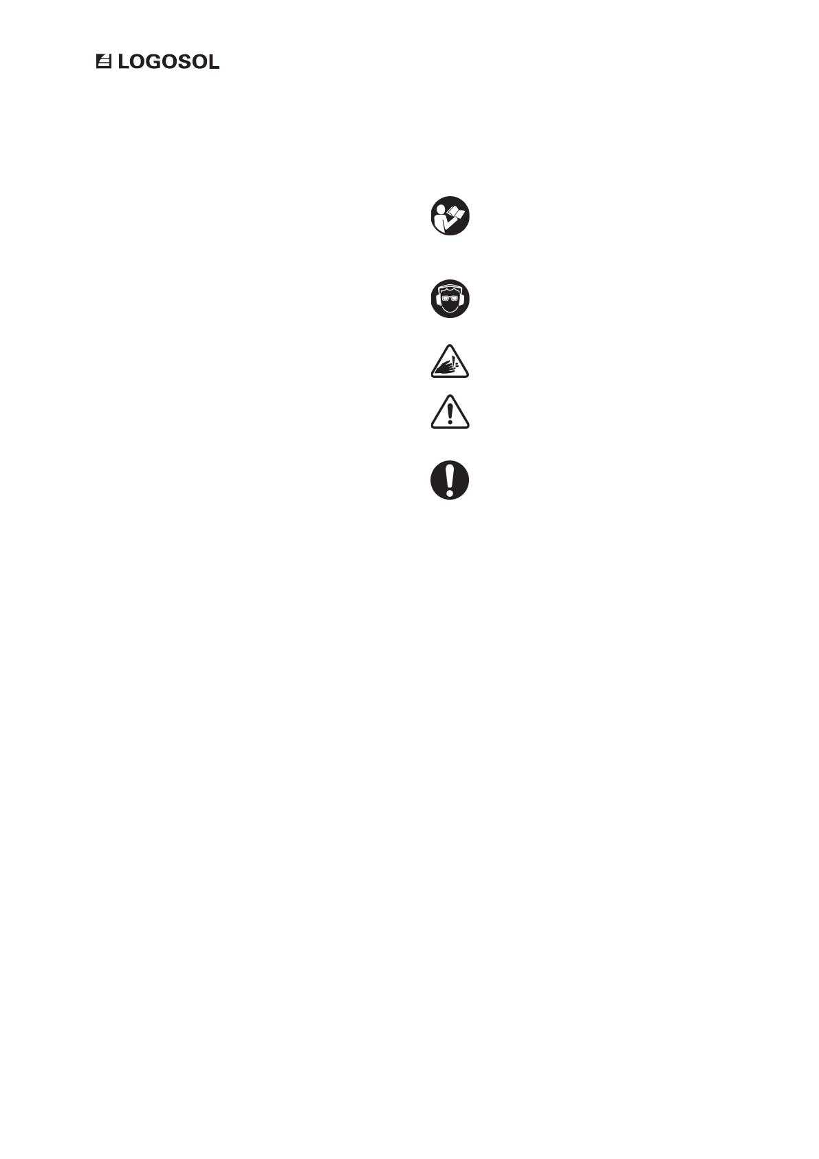
Key to symbols
For your own safety, read through the entire
user manual carefully and do not start
the machine before you have understood
everything.
Use approved ear protectors and protective
eyewear. Even short periods of exposure can
result in hearing damage.
Sharp rotating tools. Make sure to keep your
ngers away from these.
This symbol means ‘WARNING!’.
Pay particular attention where this symbol
appears in the manual text.
A warning comes after this symbol. Pay
particular attention where this symbol
appears in the manual text.