Sentera Controls FI-E11070E2 Mounting Instruction
- Type
- Mounting Instruction

Mounting and operating instructions
VARIABLE FREQUENCY
INVERTERS
FIXE

1
2
3
4
5
6
7
8
9
10
0
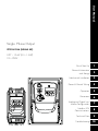
Single Phase Output
IP20 & IP66 (NEMA 4X)
0.37 – 1.1kW (0.5 – 1.5HP)
110 – 230V
1
2
3
4
5
6
7
8
9
10
User Manual
Quick Start Up
General Information
and Ratings
Mechanical Installation
Power & Control W iring
Operation
Parameters
Analog and Digital Input
Mac ro Configurations
Modbus RTU
Communications
Technical Data
Troubleshooting

2 | Optidrive ODE-3 1Ph Output User Guide | Version 2.00
www.
1. Quick Start Up . . . ................ . ... . . . ...... 4
1.1. Important Safety Information. . . . . . . . . . . . . . . . . . . . . . . . . . . . 4
1.2. Quick Start Process ........................ . . . ........ 5
1.3. Quick Start Overview . . ..................... . . . ... . . . . 6
2. General Information and Ratings . . . . . . . . . ...... . 7
2.1. Identifying the Drive by Model Number . . ....... . . . ... . . . 7
2.2. Drive Model Numbers ........................ . . . ... . . 7
3. Mechanical Installation . . . . . . ................. . 8
3.1. General .................................... . ....... 8
3.2. UL Compliant Installation ........................... . . . 8
3.3. Mechanical Dimensions and Mounting – IP20 Open Units
. . . 8
3.4. Guidelines for Enclosure Mounting – IP20 Units . . . . . . . . . . 9
3.5. Mechanical Dimensions – IP66 (NEMA 4X) Enclosed Units
. . 10
3.6. Guidelines for mounting (IP66 Units) ............... . . . . 11
3.7. Gland Plate and Lock Off ................... . . . ... . . . 11
3.8. Removing the Terminal Cover ........................ . 12
3.9. Routine Maintenance ........................ . ....... 12
4. Power & Control Wiring . .......... . . . ....... . . 13
4.1. Connection Diagram ....................... . ........ . 13
4.2. Protective Earth (PE) Connection .............. . ........ 14
4.3. Incoming Power Connection . . ................ . ....... 14
4.4. Motor Connection ......................... . . . ...... 15
4.5. Suitable Motor Types ...................... . . . ... . . . . 15
4.6. Control Terminal Wiring .................. . . . ........ . 15
4.7. Using the REV/0/FWD Selector Switch (Switched Version
Only) ................................................. 16
4.8. Control Terminal Connections ........................ . 16
4.9. Motor Thermal Overload Protection ............. . ... . . . 17
4.10. EMC Compliant Installation ...................... . . . . 17
4.11. Optional Brake Resistor ................. . . . . . ........ 18
5. Operation ... . . . ..................... . ...... 19
5.1. Managing the Keypad ...................... . ........ 19
5.2. Operating Displays . . ....................... . ........ 19
5.3. Changing Parameters ................................ 19
5.4. Read Only Parameter Access .............. . . . .... . ... 20
5.5. Resetting Parameters ......................... . . . ..... 20
5.6. Resetting a Fault .............................. . ..... . 20
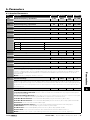
6. Parameters ............................ . . . .21
6.1. Standard Parameters . . ........................... . . 21
6.2. Extended Parameters . . . . . . . . . ................... . . 22
6.3. P-00 Read Only Status Parameters . .................. 26
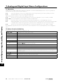
7. Analog and Digital Input Macro Configurations
. . 28
7.1. Overview . . . . . . . . . . . ............................. 28
7.2. Macro Functions Guide Key . . . . . . . . . ............. . . 28
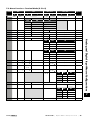
7.3. Macro Functions – Terminal Mode (P-12 = 0) . ........ . 29
7.4. Macro Functions - Keypad Mode (P-12 = 1 or 2) . . .... 30
7.5. Macro Functions - Fieldbus Control Mode (P-12 = 3, 4, 7, 8
or 9) . . .............................................. 30
7.6. Macro Functions - User PI Control Mode (P-12 = 5 or 6)
. . 31
7.7. Fire Mode . . . . . . . . . . . . ........ . ................... 31
7.8. Example Connection Diagrams . . . . . . . . . . .......... . . 32
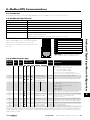
8. Modbus RTU Communications .......... . ... . . 33
8.1. Introduction . . . . . . . . . . ........................... . . 33
8.2. Modbus RTU Specification . ...................... . . 33
8.3. RJ45 Connector Configuration . . .................... 33
8.4. Modbus Register Map . . . . ......................... 10
9. Technical Data ......................... . ... 34
9.1. Environmental . . . . . . . . . . . . ....................... . . 34
9.2. Rating Tables . . . . . . . . . . . . ......................... 34
9.3. Additional Information for UL Compliance . .......... . . 34
9.4. EMC Filter Disconnect . . . . . . . . . . . .................. 35
10. Troubleshooting .................... . .... . 35
10.1. Fault Code Messages . . ........................... 36

Version 2.00 | Optidrive ODE-3 1Ph Output User Guide | 3
www.
Declaration of Conformity
Invertek Drives Ltd hereby states that the Optidrive ODE-3 product range conforms to the relevant safety provisions of the following
council directives:
2014/30/EU (EMC) and 2014/35/EU (LVD)
Designed and manufacture is in accordance with the following harmonised European standards:
EN 61800-5-1: 2007 Adjustable speed electrical power drive systems. Safety
requirements. Electrical, thermal and energy.
EN 61800-3: 2004 /A1 2012 Adjustable speed electrical power drive systems. EMC
requirements and specific test methods
EN 55011: 2007 Limits and Methods of measurement of radio disturbance
characteristics of industrial, scientific and medical (ISM) radio-
frequency equipment (EMC)
EN60529: 1992 Specifications for degrees of protection provided by enclosures
Electromagnetic Compatibility
All Optidrives are designed with high standards of EMC in mind. All versions suitable for operation on Single Phase 230 volt and
Three Phase 400 volt supplies and intended for use within the European Union are fitted with an internal EMC filter. This EMC filter
is designed to reduce the conducted emissions back into the mains supply via the power cables for compliance with the above
harmonised European standards.
It is the responsibility of the installer to ensure that the equipment or system into which the product is incorporated complies with the
EMC legislation of the country of use, and the relevant category. Within the European Union, equipment into which this product is
incorporated must comply with the EMC Directive 2004/108/EC. This User Guide provides guidance to ensure that the applicable
standards may be achieved.
Copyright Invertek Drives Ltd © 2020
All rights reserved. No part of this User Guide may be reproduced or transmitted in any form or by any means, electrical or mechanical
including photocopying, recording or by any information storage or retrieval system without permission in writing from the publisher.
2 Year Warranty
All Invertek Optidrive units carry a 2 year warranty against manufacturing defects from the date of manufacture. The manufacturer
accepts no liability for any damage caused during or resulting from transport, receipt of delivery, installation or commissioning. The
manufacturer also accepts no liability for damage or consequences resulting from inappropriate, negligent or incorrect installation,
incorrect adjustment of the operating parameters of the drive, incorrect matching of the drive to the motor, incorrect installation,
unacceptable dust, moisture, corrosive substances, excessive vibration or ambient temperatures outside of the design specification.
The local distributor may offer different terms and conditions at their discretion, and in all cases concerning warranty, the local
distributor should be contacted first.
This user guide is the “original instructions” document. All non-English versions are translations of the
“original instructions”.
The contents of this User Guide are believed to be correct at the time of printing. In the interest of a commitment to a policy of
continuous improvement, the manufacturer reserves the right to change the specification of the product or its performance or the
contents of the User Guide without notice.
This User Guide is for use with version 3.04 Firmware
User Guide Revision 2.00
Invertek Drives Ltd adopts a policy of continuous improvement and whilst every effort has been made to provide accurate and up to
date information, the information contained in this User Guide should be used for guidance purposes only and does not form the part
of any contract.
When installing the drive on any power supply where the phase-ground voltage may exceed the phase-phase voltage
(typically IT supply networks or Marine vessels) it is essential that the internal EMC filter ground and surge protection varistor
ground (where fitted) are disconnected. If in doubt, refer to your Sales Partner for further information.
This manual is intended as a guide for proper installation. Invertek Drives Ltd cannot assume responsibility for the compliance
or the non-compliance to any code, national, local or otherwise, for the proper installation of this drive or associated
equipment. A hazard of personal injury and/or equipment damage exists if codes are ignored during installation.
This Optidrive contains high voltage capacitors that take time to discharge after removal of the main supply. Before
working on the drive, ensure isolation of the main supply from line inputs. Wait ten (10) minutes for the capacitors to
discharge to safe voltage levels. Failure to observe this precaution could result in severe bodily injury or loss of life.
Only qualified electrical personnel familiar with the construction and operation of this equipment and the hazards involved
should install, adjust, operate, or service this equipment. Read and understand this manual and other applicable manuals
in their entirety before proceeding. Failure to observe this precaution could result in severe bodily injury or loss of life.

4 | Optidrive ODE-3 1Ph Output User Guide | Version 2.00
www.
Quick Start Up
1
1. Quick Start Up
1.1. Important Safety Information
Please read the IMPORTANT SAFETY INFORMATION below, and all Warning and Caution information elsewhere.
Danger: Indicates a risk of electric shock, which,
if not avoided, could result in damage to the
equipment and possible injury or death.
This variable speed drive product (Optidrive) is intended for
professional incorporation into complete equipment or systems
as part of a fixed installation. If installed incorrectly it may present
a safety hazard. The Optidrive uses high voltages and currents,
carries a high level of stored electrical energy, and is used to
control mechanical plant that may cause injury. Close attention
is required to system design and electrical installation to avoid
hazards in either normal operation or in the event of equipment
malfunction. Only qualified electricians are allowed to install
and maintain this product.
System design, installation, commissioning and maintenance
must be carried out only by personnel who have the necessary
training and experience. They must carefully read this safety
information and the instructions in this Guide and follow all
information regarding transport, storage, installation and use of
the Optidrive, including the specified environmental limitations.
Do not perform any flash test or voltage withstand test on the
Optidrive. Any electrical measurements required should be
carried out with the Optidrive disconnected.
Electric shock hazard! Disconnect and ISOLATE the Optidrive
before attempting any work on it. High voltages are present
at the terminals and within the drive for up to 10 minutes after
disconnection of the electrical supply. Always ensure by using a
suitable multimeter that no voltage is present on any drive power
terminals prior to commencing any work.
Where supply to the drive is through a plug and socket
connector, do not disconnect until 10 minutes have elapsed after
turning off the supply.
Ensure correct earth connections and cable selection as per
defined by local legislation or codes. The drive may have a
leakage current of greater than 3.5mA; furthermore the earth
cable must be sufficient to carry the maximum supply fault current
which normally will be limited by the fuses or MCB.
Suitably rated fuses or MCB should be fitted in the mains supply
to the drive, according to any local legislation or codes.
Do not carry out any work on the drive control cables whilst
power is applied to the drive or to the external control circuits.
Danger: Indicates a potentially hazardous situation
other than electrical, which if not avoided, could
result in damage to property.
Within the European Union, all machinery in which this product
is used must comply with Directive 2006/42/EC, Safety of
Machinery. In particular, the machine manufacturer is responsible
for providing a main switch and ensuring the electrical equipment
complies with EN60204-1.
Whilst every effort is made to ensure the contents of this user
guide are applicable to the wides range of applications and
installations, it is the responsibility of the installer to ensure
compliance with any local codes or regulations relevant to the
installation location.
The level of integrity offered by the Optidrive control input
functions – for example stop/start, maximum speed, etc. is
not sufficient for use in safety-critical applications without
independent channels of protection. All applications where
malfunction could cause injury or loss of life must be subject to a
risk assessment and further protection provided where needed.
The driven motor can start at power up if the enable input signal
is present.
The STOP function does not remove potentially lethal high
voltages. ISOLATE the drive and wait 10 minutes before starting
any work on it. Never carry out any work on the Drive, Motor or
Motor cable whilst the input power is still applied.
The Optidrive can be programmed to operate the driven motor
at speeds above or below the speed achieved when connecting
the motor directly to the mains supply. Obtain confirmation from
the manufacturers of the motor and the driven machine about
suitability for operation over the intended speed range prior to
machine start up.
Do not activate the automatic fault reset function on any systems
whereby this may cause a potentially dangerous situation.
IP20 drives must be installed in a pollution degree 2 environment
mounted in a cabinet with IP54 or better.
Optidrives are intended for indoor use only.
When mounting the drive, ensure that sufficient cooling is provided.
Do not carry out drilling operations with the drive in place, dust
and swarf from drilling may lead to damage.
The entry of conductive or flammable foreign bodies should be
prevented. Flammable material should not be placed close to
the drive.
Relative humidity must be less than 95% (non-condensing).
Ensure that the supply voltage, frequency and no. of phases (1 or
3 phase) correspond to the rating of the Optidrive as delivered.
Never connect the mains power supply to the Output terminals
U, V, W.
Do not install any type of automatic switchgear between the
drive and the motor.
Wherever control cabling is close to power cabling, maintain
a minimum separation of 100 mm and arrange crossings
at 90 degrees. Ensure that all terminals are tightened to the
appropriate torque setting.
Do not attempt to carry out any repair of the Optidrive. In
the case of suspected fault or malfunction, contact your local
Invertek Drives Sales Partner for further assistance.

Version 2.00 | Optidrive ODE-3 1Ph Output User Guide | 5
www.
Quick Start Up
1
1.2. Quick Start Process
Step Action See section Page
1 Identify the Enclosure Type, Model Type and ratings of
your drive from the model code on the label. In particular
- Check the voltage rating suits the incoming supply
- Check the output current capacity meets or exceeds the
full load current for the intended motor
2.1. Identifying the Drive by Model Number 7
2 Unpack and check the drive. Notify the supplier and
shipper immediately of any damage.
3 Ensure correct ambient and environmental conditions for
the drive are met by the proposed mounting location.
9.1. Environmental 34
4 Install the drive in a suitable cabinet (IP20 Units) ensuring
suitable cooling air is available.
Mount the drive to the wall or machine (IP66).
3.1. General
3.3. Mechanical Dimensions and Mounting – IP20
Open Units
3.4. Guidelines for Enclosure Mounting – IP20 Units
3.5. Mechanical Dimensions – IP66 (NEMA 4X)
Enclosed Units
3.6. Guidelines for mounting (IP66 Units)
8
8
9
10
11
5 Select the correct power and motor cables according
to local wiring regulations or code, noting the maximum
permissible sizes
9.2. Rating Tables 34
6 If the supply type is IT or corner grounded, disconnect the
EMC filter before connecting the supply.
9.4. EMC Filter Disconnect 35
7 Check the supply cable and motor cable for faults or short
circuits.
8 Route the cables
9 Check that the intended motor is suitable for use, noting
any precautions recommended by the supplier or
manufacturer.
10 Check the motor cable length does not exceed the
maximum allowed for the drive unit
- 100m (328ft) shielded cable maximum
- 150m (293ft) unshielded cable maximum
- 200m (656ft) shielded cable maximum with optional
external output filter
- 300m (984ft) unshielded cable maximum with optional
external output filter
11 Ensure wiring protection is providing, by installing a
suitable circuit breaker or fuses in the incoming supply line
4.3.2. Fuse / Circuit Breaker Selection
9.2. Rating Tables
14
34
12 Connect the power cables, especially ensuring the
protective earth connection is made
4.1. Connection Diagram
4.2. Protective Earth (PE) Connection
4.3. Incoming Power Connection
4.4. Motor Connection
13
14
14
15
13 Connect the control cables as required for the application 4.6. Control Terminal Wiring
7. Analog and Digital Input Macro Configurations
7.8. Example Connection Diagrams
15
28
32
14 Thoroughly check the installation and wiring
15 Ensure that all aspects of the installation comply with local
codes and regulations relevant to the installation location
16 Commission the drive parameters 5.1. Managing the Keypad
6. Parameters
19
21

6 | Optidrive ODE-3 1Ph Output User Guide | Version 2.00
www.
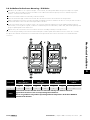
1.3. Quick Start Overview
Quick Start – IP20 & IP66 Non Switched
Connect a Start / Stop switch between control
terminals 1 & 2
o Close the Switch to Start
o Open to Stop
Connect a potentiometer (5k – 10kΩ) between terminals 5,
6 and 7 as shown
o Adjust the potentiometer to vary the speed from P-02
(0Hz default) to P-01 (50 / 60 Hz default)
Quick Start – IP66 Switched
Switch the mains power on to the unit using the built in isolator
switch on the front panel.
The OFF/REV/FWD will enable the output and control the
direction of rotation of the motor.
NOTE: With single phase motors, forward rotation
only is possible.
The potentiometer will control the motor shaft rotational speed.
0
Quick Start Up
1

Version 2.00 | Optidrive ODE-3 1Ph Output User Guide | 7
www.
General Information and Ratings
2
2. General Information and Ratings
This chapter contains information about the Optidrive E3 including how to identify the drive.
2.1. Identifying the Drive by Model Number
Each drive can be identified by its model number, as shown in the table below. The model number is on the shipping label and the
drive nameplate. The model number includes the drive and any options.
ODE -3-1 2 0021 - 1F1 2 - 01 Single Phase Output
Product Family IP Rating 2 = IP20
X = IP66 Non Switched
Y = IP66 Switched
Generation Dynamic Brake
Transistor
1 = Not Fitted
4 = Internal Transistor
Frame Size Filter Type 0 = No Filter
F = Internal EMC Filter
Input Voltage 1 = 110 – 115 No. Of Input Phases
2 = 200 – 240 Output Current x 10
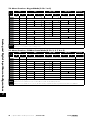
2.2. Drive Model Numbers
110 – 115V + / - 10% - 1Phase Input – 1 Phase 110V Output
Model Number kW HP Output Current
(A) Frame Size
With Filter Without Filter
N/A ODE-3-110070-101#-01 0.5 7.0 1
N/A ODE-3-210105-104#-01 0.75 10.5 2
200 – 240V + / - 10% - 1Phase Input – 1 Phase Output
Model Number kW HP Output Current
(A) Frame Size
With Filter Without Filter
ODE-3-120043-1F1#-01 ODE-3-120043-101#-01 0.37 0.5 4.3 1
ODE-3-120070-1F1#-01 ODE-3-120070-101#-01 0.75 1 7.0 1
ODE-3-220105-1F4#-01 ODE-3-220105-104#-01 1.1 1.5 10.5 2
NOTE
For IP20 units, replace ‘#’ with ‘2’
For IP66 Non Switched Units, replace ‘#’ with ‘X’
For IP66 Switched Units, replace ‘#’ with ‘Y’

8 | Optidrive ODE-3 1Ph Output User Guide | Version 2.00
www.
3
Mechanical Installation
3. Mechanical Installation
3.1. General
The Optidrive should be mounted in a vertical position only, on a flat, flame resistant, vibration free mounting using the integral
mounting holes or DIN Rail clip (Frame Sizes 1 and 2 only).
IP20 Optidrives must be installed in a pollution degree 1 or 2 environment only.
Do not mount flammable material close to the Optidrive.
Ensure that the minimum cooling air gaps, as detailed in section 3.5. Mechanical Dimensions – IP66 (NEMA 4X) Enclosed Units
and 3.7. Gland Plate and Lock Off are left clear.
Ensure that the ambient temperature range does not exceed the permissible limits for the Optidrive given in section 9.1.
Environmental.
Provide suitable clean, moisture and contaminant free cooling air sufficient to fulfil the cooling requirements of the Optidrive.
3.2. UL Compliant Installation
Refer to section 9.3. Additional Information for UL Compliance on page 34 for Additional Information for UL Compliance.
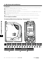
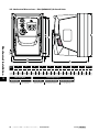
3.3. Mechanical Dimensions and Mounting – IP20 Open Units
L1/L L3
L2/N
Drive
Size
A B C D E F Weight
mm in mm in mm in mm in mm in mm in Kg Ib
1 173 6.81 83 3.27 123 4.84 162 6.38 50 1.97 50 1.97 1.0 2.2
2 221 8.70 110 4.33 150 5.91 209 8.23 63 2.48 63 2.48 1.7 3.8
Mounting Bolts Tightening Torques
Frame Size Frame Size Control Terminals Power Terminals
1 – 2 4 x M5 (#8) 1 – 2 0.5 Nm (4.5 lb-in) 1 Nm (9 lb-in)

Version 2.00 | Optidrive ODE-3 1Ph Output User Guide | 9
www.
Mechanical Installation
3
3.4. Guidelines for Enclosure Mounting – IP20 Units
IP20 drives are suitable for use in pollution degree 1 environments, according to IEC-664-1. For pollution degree 2 or higher
environments, drives should be mounted in a suitable control cabinet with sufficient ingress protection to maintain a pollution
degree 1 environment around the drive.
Enclosures should be made from a thermally conductive material.
Ensure the minimum air gap clearances around the drive as shown below are observed when mounting the drive.
Where ventilated enclosures are used, there should be venting above the drive and below the drive to ensure good air circulation.
Air should be drawn in below the drive and expelled above the drive.
In any environments where the conditions require it, the enclosure must be designed to protect the Optidrive against ingress of
airborne dust, corrosive gases or liquids, conductive contaminants (such as condensation, carbon dust, and metallic particles) and
sprays or splashing water from all directions.
High moisture, salt or chemical content environments should use a suitably sealed (non-vented) enclosure.
The enclosure design and layout should ensure that the adequate ventilation paths and clearances are left to allow air to circulate
through the drive heatsink. Invertek Drives recommend the following minimum sizes for drives mounted in non-ventilated metallic
enclosures:
Drive Size
X
Above & Below
Y
Either Side
Z
Between
Recommended
airflow
mm in mm in mm in CFM (ft3/min)
1 50 1.97 50 1.97 33 1.30 11
2 75 2.95 50 1.97 46 1.81 22
NOTE
Dimension Z assumes that the drives are mounted side-by-side with no clearance.
Typical drive heat losses are 3% of operating load conditions.
Above are guidelines only and the operating ambient temperature of the drive MUST be
maintained at all times.

10 | Optidrive ODE-3 1Ph Output User Guide | Version 2.00
www.
3
Mechanical Installation
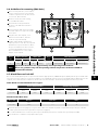
3.5. Mechanical Dimensions – IP66 (NEMA 4X) Enclosed Units
0
Drive
Size
A B D E F G H I J Weight
mm in mm in mm in mm in mm in mm in mm in mm in mm in kg Ib
1
232.0 9.13 207.0 8.15 189.0 7.44 25.0 0.98 179.0 7.05 161.0 6.34 148.5 5.85 4.0 0.16 8.0 0.31 3.1 6.8
2 257.0 10.12 220.0 8.67 200.0 7.87 28.5 1.12 187.0 7.36 188.0 7.40 176.0 6.93 4.2 0.17 8.5 0.33 4.1 9.0
Mounting Bolts Tightening Torques
Frame Size Frame Size Control Terminals Power Terminals
All Frame Sizes 4 x M4 (#8) All Frame Sizes 0.5 Nm (4.5 lb-in) 1 Nm (9 lb-in)

Version 2.00 | Optidrive ODE-3 1Ph Output User Guide | 11
www.
3
Mechanical Installation
3.6. Guidelines for mounting (IP66 Units)
Before mounting the drive, ensure that the
chosen location meets the environmental
condition requirements for the drive shown
in section 9.1. Environmental.
The drive must be mounted vertically,
on a suitable flat surface.
The minimum mounting clearances
as shown in the table below must be
observed.
The mounting site and chosen mountings
should be sufficient to support the weight
of the drives.
Using the drive as a template, or the
dimensions shown above, mark the
locations required for drilling.
Suitable cable glands to maintain the
ingress protection of the drive are required.
Gland holes for power and motor cables
are pre-moulded into the drive enclosure,
recommended gland sizes are shown
above. Gland holes for control cables
may be cut as required.
Drive
Size
X Above & Below Y Either Side Drive
Size
Cable Gland Sizes
mm in mm in Power Cable Motor Cable Control Cables
1 200 7.87 10 0.39 1 M20 (PG13.5) M20 (PG13.5) M20 (PG13.5)
2 200 7.87 10 0.39 2 M25 (PG21) M25 (PG21) M20 (PG13.5)
NOTE
Typical drive heat losses are approximately 3% of operating load conditions.
Above are guidelines only and the operating ambient temperature of the drive MUST be
maintained at all times.
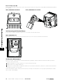
3.7. Gland Plate and Lock Off
The use of a suitable gland system is required to maintain the appropriate IP / NEMA rating. The gland plate has pre moulded cable
entry holes for power and motor connections suitable for use with glands as shown in the following table. Where additional holes are
required, these can be drilled to suitable size. Please take care when drilling to avoid leaving any particles within the product.
Cable Gland recommended Hole Sizes & types:
Power & Motor Cables Control & Signal Cables
Drive Size Power Cable Motor Cable Control Cables Power Cable Motor Cable Control Cables
Size 1 22mm PG13.5 M20 22mm PG13.5 M20
Size 2 & 3 27mm PG21 M25 22mm PG13.5 M20
Flexible Conduit Hole Sizes:
Drive Size Drill Size Trade Size Metric
Size 1 28mm ¾ in 21
Size 2 & 3 35mm 1 in 27
UL rated ingress protection ("Type" ) is only met when cables are installed using a UL recognized bushing or fitting for a flexible-
conduit system which meets the required level of protection ("Type").
For conduit installations the conduit entry holes require standard opening to the required sizes specified per the NEC.
Not intended for installation using rigid conduit system.
0 0

12 | Optidrive ODE-3 1Ph Output User Guide | Version 2.00
www.
Power Isolator Lock Off
On the switched models the main power isolator switch can be locked in the ‘Off’ position using a 20mm standard shackle padlock
(not supplied).
IP66 / NEMA 4X Gland Plate IP66 / NEMA 4X Unit Lock Off
3.8. Removing the Terminal Cover
To access the connection terminals, the drive front cover needs to be removed as shown.
IP66 / NEMA 4X Units
Removing the 2 screws on the front of the product allows access to the connection terminals, as shown below.
0
3.9. Routine Maintenance
The drive should be included within the scheduled maintenance program so that the installation maintains a suitable operating
environment, this should include:
Ambient temperature is at or below that set out in section 9.1. Environmental.
Heat sink fans freely rotating and dust free.
The Enclosure in which the drive is installed should be free from dust and condensation; furthermore ventilation fans and air filters
should be checked for correct air flow.
Checks should also be made on all electrical connections, ensuring screw terminals are correctly torqued; and that power cables
have no signs of heat damage.
3
Mechanical Installation

Version 2.00 | Optidrive ODE-3 1Ph Output User Guide | 13
www.
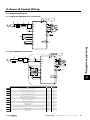
4. Power & Control Wiring
4.1. Connection Diagram
4.1.1. IP20 & IP66 (NEMA 4X) Non-Switched Units
4.1.2. IP66 (NEMA 4X) Switched Units
Key Sec. Page
AProtective Earth (PE) Connection 4.2 14
BIncoming Power Connection 4.3 14
CFuse / Circuit Breaker Selection 4.3.2 14
DOptional Input Choke 4.3.3 15
EOptional External EMC Filter 4.10 17
FInternal Disconnect / Isolator 4.3 14
GOptional Brake Resistor 4.11 18
HMotor Connection
IAnalog Output 4.8.1 16
JRelay Output 4.8.2 17
KUsing the REV/0/FWD Selector Switch (Switched Version Only) 4.7 16
LAnalog Inputs 4.8.3 17
MDigital Inputs 4.8.4 17
M
D
Power & Control Wiring
4

14 | Optidrive ODE-3 1Ph Output User Guide | Version 2.00
www.
Power & Control Wiring
4
4.2. Protective Earth (PE) Connection
Grounding Guidelines
The ground terminal of each Optidrive should be individually connected DIRECTLY to the site ground bus bar (through the filter if
installed). Optidrive ground connections should not loop from one drive to another, or to, or from any other equipment. Ground loop
impedance must confirm to local industrial safety regulations. To meet UL regulations, UL approved ring crimp terminals should be
used for all ground wiring connections.
The drive Safety Ground must be connected to system ground. Ground impedance must conform to the requirements of national and
local industrial safety regulations and/or electrical codes. The integrity of all ground connections should be checked periodically.
Protective Earth Conductor
The Cross sectional area of the PE Conductor must be at least equal to that of the incoming supply conductor.
Safety Ground
This is the safety ground for the drive that is required by code. One of these points must be connected to adjacent building steel
(girder, joist), a floor ground rod, or bus bar. Grounding points must comply with national and local industrial safety regulations and/
or electrical codes.
Motor Ground
The motor ground must be connected to one of the ground terminals on the drive.
Ground Fault Monitoring
As with all inverters, a leakage current to earth can exist. The Optidrive is designed to produce the minimum possible leakage current
whilst complying with worldwide standards. The level of current is affected by motor cable length and type, the effective switching
frequency, the earth connections used and the type of RFI filter installed. If an ELCB (Earth Leakage Circuit Breaker) is to be used, the
following conditions apply:
A Type B Device must be used.
The device must be suitable for protecting equipment with a DC component in the leakage current.
Individual ELCBs should be used for each Optidrive.
Shield Termination (Cable Screen)
The safety ground terminal provides a grounding point for the motor cable shield. The motor cable shield connected to this terminal
(drive end) should also be connected to the motor frame (motor end). Use a shield terminating or EMI clamp to connect the shield to
the safety ground terminal.
4.3. Incoming Power Connection
4.3.1. Cable Selection
The mains power cables should be connected to L1/L, L2/N.
For compliance with CE and C Tick EMC requirements, refer to section 4.10. EMC Compliant Installation on page 17.
A fixed installation is required according to IEC61800-5-1 with a suitable disconnecting device installed between the Optidrive
and the AC Power Source. The disconnecting device must conform to the local safety code / regulations (e.g. within Europe,
EN60204-1, Safety of machinery).
The cables should be dimensioned according to any local codes or regulations. Maximum dimensions are given in section 9.2.
Rating Tables.
4.3.2. Fuse / Circuit Breaker Selection
Suitable fuses to provide wiring protection of the input power cable should be installed in the incoming supply line, according to
the data in section 9.2. Rating Tables. The fuses must comply with any local codes or regulations in place. In general, type gG (IEC
60269) or UL type J fuses are suitable; however in some cases type aR fuses may be required. The operating time of the fuses must
be below 0.5 seconds.
Where allowed by local regulations, suitably dimensioned type B MCB circuit breakers of equivalent rating may be utilised in
place of fuses, providing that the clearing capacity is sufficient for the installation.
The maximum permissible short circuit current at the Optidrive Power terminals as defined in IEC60439-1 is 100kA.

Version 2.00 | Optidrive ODE-3 1Ph Output User Guide | 15
www.
Power & Control Wiring
4
4.3.3. Optional Input Choke
An optional Input Choke is recommended to be installed in the supply line for drives where any of the following conditions occur:
o The incoming supply impedance is low or the fault level / short circuit current is high.
o The supply is prone to dips or brown outs.
o The power supply to the drive is via a busbar and brush gear system (typically overhead Cranes).
In all other installations, an input choke is recommended to ensure protection of the drive against power supply faults. Part numbers
are shown in the table.
Supply Frame Size AC Input Inductor
110 & 230 Volt
1 Phase
1 OPT-2-L1016-20
2 OPT-2-L1025-20
4.4. Motor Connection
The drive inherently produces fast switching of the output voltage (PWM) to the motor compared to the mains supply. For motors
which have been wound for operation with a variable speed drive then there is no preventative measures required, however if the
quality of insulation is unknown then the motor manufacturer should be consulted and preventative measures may be required.
The motor should be connected to the Optidrive U, and V terminals using a suitable 2 or 3 core cable. Where a 2 core cable is
utilised, with the shield operating as an earth conductor, the shield must have a cross sectional area at least equal to the phase
conductors when they are made from the same material. Where a 3 core cable is utilised, the earth conductor must be of at least
equal cross sectional area and manufactured from the same material as the phase conductors.
The motor earth must be connected to one of the Optidrive earth terminals.
4.5. Suitable Motor Types
Optidrive E3 Single Phase Output is intended for use with the following motor types:
PSC (Permanent Split Capacitor)
Shaded Pole
The motor should be suitable for operation with a PWM inverter. If in doubt, consult the motor manufacturer for guidance - additional
filtering may be required to prevent damage to the motor.
4.6. Control Terminal Wiring
All analog signal cables should be suitably shielded. Twisted pair cables are recommended.
Power and Control Signal cables should be routed separately where possible, and must not be routed parallel to each other.
Signal levels of different voltages e.g. 24 Volt DC and 110 Volt AC, should not be routed in the same cable.
Maximum control terminal tightening torque is 0.5Nm.
Control Cable entry conductor size: 0.05 – 2.5mm2 / 30 – 12 AWG.

16 | Optidrive ODE-3 1Ph Output User Guide | Version 2.00
www.
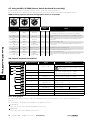
4.7. Using the REV/0/FWD Selector Switch (Switched Version Only)
By adjusting the parameter settings the Optidrive can be configured for multiple applications.
This could typically be for Hand/Off/Auto applications (also known as Local/Remote) for HVAC and pumping industries.
NOTE Forward / Reverse operation of single phase motors is not possible.
Switch Position
Parameters
to Set Notes
P-12 P-15
Run (Pot) STOP Run (Pot) 0 0 Factory Default Configuration
Run Forward only with speed controlled from the Local POT
Run
(Preset Speed 1) STOP Run (Pot) 0 1 Run forward with speed controlled form the local POT or preset
speed
Run
(Analog Input 2) STOP Run (Pot) 0 4 Run Forward with speed controlled from the Local POT or 2nd
analog input
Enable STOP Enable 3, 4 0 Control from Modbus RTU
Run
(Preset Speed 1) STOP Enable
(Modbus RTU) 3, 4 5 Local / Remote function with Modbus RTU speed reference or
preset speed
Run
(Preset Speed 1) STOP Run in PI Control 5, 6 0 Selectable PI control or preset speed
Run (Pot) STOP Run in PI Control 5, 6 0 Selectable PI control or Pot speed control
Enable STOP Enable 7, 8 0 Control from CAN interface
Run
(Preset Speed 1) STOP Enable
(Modbus RTU) 7, 8 5 Local / Remote function with CAN speed reference or preset
speed
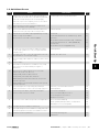
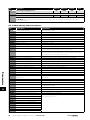
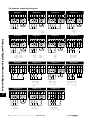
4.8. Control Terminal Connections
Default Connections Control Terminal Signal Description
1 +24Vdc User Output
+24Vdc user output, 100mA.
Do not connect an external voltage source to
this terminal.
2 Digital Input 1 Positive logic
“Logic 1” input voltage range: 8V … 30V DC
“Logic 0” input voltage range: 0V … 4V DC
3 Digital Input 2
4Digital Input 3 /
Analog Input 2
Digital: 8 to 30V
Analog: 0 to 10V, 0 to 20mA or 4 to 20mA
5 +10V User Output +10V, 10mA, 1kΩ minimum
6Analog Input 1 /
Digital Input 4
Analog: 0 to 10V, 0 to 20mA or 4 to 20mA
Digital: 8 to 30V
7 0V 0 Volt Common, internally connected to terminal 9
8Analog Output /
Digital Output
Analog: 0 to 10V,
Digital: 0 to 24V 20mA maximum
9 0V 0 Volt Common, internally connected to terminal 7
10 Relay Common
11 Relay NO Contact Contact 250Vac, 6A / 30Vdc, 5A
4.8.1. Analog Output
The analog output function may be configured using parameter P-25, which is described in section 6.2. Extended Parameters on
page 22.
The output has two operating modes, dependent on the parameter selection:
Analog Mode
o The output is a 0 – 10 volt DC signal, 20mA max load current.
Digital Mode
o The output is 24 volt DC, 20mA max load current.
Power & Control Wiring
4

Version 2.00 | Optidrive ODE-3 1Ph Output User Guide | 17
www.
4.8.2. Relay Output
The relay output function may be configured using parameter P-18, which is described in section 6.2. Extended Parameters on page 22.
4.8.3. Analog Inputs
Two analog inputs are available, which may also be used as Digital Inputs if required. The signal formats are selected by parameters
as follows:
Analog Input 1 Format Selection Parameter P-16.
Analog Input 2 Format Selection Parameter P-47.
These parameters are described more fully in section 6.2. Extended Parameters on page 22.
The function of the analog input, e.g. for speed reference or PID feedback for example is defined by parameters P-15. The function of
these parameters and available options is described in section 7. Analog and Digital Input Macro Configurations on page 28.
4.8.4. Digital Inputs
Up to four digital inputs are available. The function of the inputs is defined by parameters P-12 and P-15, which are explained in
section 7. Analog and Digital Input Macro Configurations on page 28.
4.9. Motor Thermal Overload Protection
4.9.1. Internal Thermal Overload Protection
The drive has an in-built motor thermal overload function; this is in the form of an “I.t-trP” trip after delivering >100% of the value set in
P-08 for a sustained period of time (e.g. 150% for 60 seconds).
4.9.2. Motor Thermistor Connection
Where a motor thermistor is to be used, it should be connected as follows:
Control Terminal Strip Additional Information
Compatible Thermistor: PTC Type, 2.5kΩ trip level.
Use a setting of P-15 that has Input 3 function as External Trip,
e.g. P-15 = 3. Refer to section 7. Analog and Digital Input Macro
Configurations on page 28 for further details.
Set P-47 = “ "
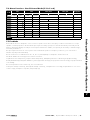
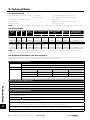
4.10. EMC Compliant Installation
Category Supply Cable Type Motor Cable Type Control Cables Maximum Permissible
Motor Cable Length
C16Shielded1Shielded1,5
Shielded4
1M / 5M7
C2 Shielded2Shielded1, 5 5M / 25M7
C3 Unshielded3Shielded225M / 100M7
1 A screened (shielded) cable suitable for fixed installation with the relevant mains voltage in use. Braided or twisted type screened
cable where the screen covers at least 85% of the cable surface area, designed with low impedance to HF signals. Installation of
a standard cable within a suitable steel or copper tube is also acceptable.
2 A cable suitable for fixed installation with relevant mains voltage with a concentric protection wire. Installation of a standard cable
within a suitable steel or copper tube is also acceptable.
3 A cable suitable for fixed installation with relevant mains voltage. A shielded type cable is not necessary.
4 A shielded cable with low impedance shield. Twisted pair cable is recommended for analog signals.
5 The cable screen should be terminated at the motor end using an EMC type gland allowing connection to the motor body
through the largest possible surface area. Where drives are mounted in a steel control panel enclosure, the cable screen may be
terminated directly to the control panel using a suitable EMC clamp or gland, as close to the drive as possible. For IP66 drives,
connect the motor cable screen to the internal ground clamp.
6 Compliance with category C1 conducted emissions only is achieved. For compliance with category C1 radiated emissions,
additional measures may be required, contact your Sales Partner for further assistance.
7 Permissible cable length with additional external EMC filter.
Power & Control Wiring
4

18 | Optidrive ODE-3 1Ph Output User Guide | Version 2.00
www.
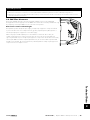
4.11. Optional Brake Resistor
Optidrive E3 Frame Size 2 and above units have a built in Brake Transistor. This allows an external resistor to be connected to the
drive to provide improved braking torque in applications that require this.
The brake resistor should be connected to the “+” and “BR” terminals as shown.
The voltage level at these terminals may exceed 400VDC.
Stored charge may be present after disconnecting the mains power.
Allow a minimum of 10 minutes discharge after power off before attempting any connection to these terminals.
Suitable resistors and guidance on selection can be obtained from your Invertek Sales Partner.
Power & Control Wiring
4

Version 2.00 | Optidrive ODE-3 1Ph Output User Guide | 19
www.
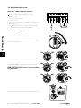
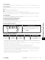
5. Operation
5.1. Managing the Keypad
The drive is configured and its operation monitored via the keypad and display.
NAVIGATE Used to display real-time information, to access and exit
parameter edit mode and to store parameter changes.
UP Used to increase speed in real-time mode or to increase
parameter values in parameter edit mode.
DOWN Used to decrease speed in real-time mode or to
decrease parameter values in parameter edit mode.
RESET /
STOP
Used to reset a tripped drive.
When in Keypad mode is used to Stop a running drive.
START
When in keypad mode, used to Start a stopped drive or
to reverse the direction of rotation if
bi-directional keypad mode is enabled.
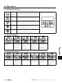
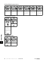
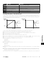
5.2. Operating Displays
Drive Stopped /
Disabled
Drive is enabled
/ running, display
shows the output
frequency (Hz)
Press the Navigate
key for < 1 second.
The display will
show the motor
current (Amps)
Press the Navigate
key for < 1 second.
The display will
show the motor
power (kW)
If P-10 > 0, pressing
the Navigate key
for < 1 second will
display the motor
speed (RPM)
5.3. Changing Parameters
Press and hold the
Navigate key > 2
seconds
Use the up and
down keys to
select the required
parameter
Press the Navigate
key for < 1 second
Adjust the value
using the Up and
Down keys
Press for < 1 second
to return to the
parameter menu
Press for > 2
seconds to return
to the operating
display
Operation
5
Page is loading ...
Page is loading ...
Page is loading ...
Page is loading ...
Page is loading ...
Page is loading ...
Page is loading ...
Page is loading ...
Page is loading ...
Page is loading ...
Page is loading ...
Page is loading ...
Page is loading ...
Page is loading ...
Page is loading ...
Page is loading ...
Page is loading ...
-
 1
1
-
 2
2
-
 3
3
-
 4
4
-
 5
5
-
 6
6
-
 7
7
-
 8
8
-
 9
9
-
 10
10
-
 11
11
-
 12
12
-
 13
13
-
 14
14
-
 15
15
-
 16
16
-
 17
17
-
 18
18
-
 19
19
-
 20
20
-
 21
21
-
 22
22
-
 23
23
-
 24
24
-
 25
25
-
 26
26
-
 27
27
-
 28
28
-
 29
29
-
 30
30
-
 31
31
-
 32
32
-
 33
33
-
 34
34
-
 35
35
-
 36
36
-
 37
37


Sentera Controls FI-E11070E2 Mounting Instruction
- Type
- Mounting Instruction
Ask a question and I''ll find the answer in the document
Finding information in a document is now easier with AI
Related papers


Other documents
-
 Invertek Optidrive ODE-2-32040-1K04 User manual
-
 Invertek Drives Optidrive ODP-2 User manual
-
 Chore-Time MV2493 User manual
-
 Chore-Time MV2492A INVERTEK OPTIDRIVE™ VFD Quick start guide
-
Cumberland Commander Series Fan Owner's manual
-
-
-
 Invertek OPT-2-ENCOD-IN User manual
-
 Invertek OPTIPAD Operating instructions
-
Miller MK000000 Owner's manual


