Page is loading ...

1.0 GENERAL INFORMATION
Thank you for purchasing the Setra Remote Monitoring Display (SRMD). The
SRMD is a digital panel meter with a bright 1” LED display for visibility at a
distance.
Before installing, please check the box and ensure the following items are
included:
1. Mounting Plate (with single or dual display in color(s) ordered:
green, red, or blue)
2. Faceplate Bezel (White or Metallic Finish, as ordered)
3. Engineering units label set
Note: If a dual display is ordered with a SRH temperature or humidity sensor and a color specified to match
each (or your own sensors), wire the correct sensor to the correct display.
The SRMD can be powered by 24 VAC/DC and can accept 0 to 5 or 0 to 10
VDC transducer signals from remote sensors. These field sensors can be tem-
perature, humidity, CO2, etc.
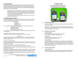
Fig. 1.
Model SRMD
Setra Remote Monitoring Display
Mounting Plate
Grommets for
Faceplate/Bezel
Faceplate/Bezel Engineering Unit Labels

2.0 INSTALLATION
2.1 Rough-In (see Fig 2.)
Install the SRMD in a 4 11/16” square electrical box. Run the power and signal
wiring into the box. Two wires are for the 24 VAC/DC power, and two wires are
for each of the signal lines from the field sensors to the display. For example,
the single display version would be 2 wires and the dual display needs 2 wires
for each of the two displays.
Run the wiring to the 24 VAC/DC source and to the sensors that are to be
monitored. The power to the sensors is not supplied by the displays.
2.2 Positioning the Front of the Electrical Box
It is very important that the box be set 1/16” to 1/8” below the finish wall so
that the faceplate will seal against the finished wall. If possible allow for ad-
justment at the finish stage to set the depth correctly.
Fig. 2

3.0 WIRING TO THE DISPLAYS
Shown in Fig. 3 is a wiring diagram and picture of the back of the mounting
plate. Note that each display has a terminal strip. If you are using field sensors
that are not Setra’s SRH humidity/temperature sensors, then calibrate the display
according to Section 4 before completing the wiring shown here.
Fig. 3
Wiring:
+E - Excitation, 24 VAC
COM - 2 terminals connected together, wire
to 24 VAC and to common of the field sensor
+S - wire to the field sensor
Input Wiring

4.0 CALIBRATION
Power the display(s). If you have the Setra humidity and temperature sen-
sor, then the displays are already calibrated and ready to use. If you are using
other sensors, then you must calibrate the displays output signal to the engi-
neering units, unless your sensors are 0 to 5 or 0 to 10 V output and display 0
to 100 (factory default setting).
Calibration requires a calibrated Voltage Source to simulate the sensor analog
output.
Set range dip switch to either 5 V (for a 0 to 5 V input ) or 10 V (for a 0 to 10 V
input) position.
The factory default calibration of the display is 0 to 5 VDC field sensor input,
which will produce a display reading of 0.0 at 0 V and 100.0 at 5 V. Also, if the
range jumper switch is set to the 10 V input position, then the calibration will
be 0.0 to 0 V and 100.0 at 10 V.
Fig. 4
Input Wiring

4.2 Zero and Span Calibration
Set the Voltage Source to 0 VDC and Connect the Voltage Source to the +S
and COM terminals on the display.
Check the field sensor input and output specification.
Example:
Humidity Sensor 0-100% RH and 0 to 5 VDC output
Temperature Sensor 50-90°F and 0 to 10 VDC output
Setup Humidity Sensor:
Apply 0 V and if necessary turn the ZERO potentiometer (pot) until the display
reads 0.0, apply 5 VDC and turn the pot labeled 5V until the display reads
100.0
Setup Temperature Sensor:
Move the range jumper from the 5V to 10V position. Apply 0 VDC and turn
ZERO pot until the display reads 50.0, apply 10V and turn 10V pot until display
reads 90.0
4.3 Adjust Display Brightness
While looking at the display, turn the Display brightness adjust pot, (See Fig. 4)
to the desired brightness.

5.0 INSTALL MOUNTING PLATE
After adjusting and verifying the depth of the electrical box relative to the
finish wall (see, Fig. 2), install the mounting plate to the electrical box. Be sure
that the displays are installed right side up. Install the 2 mounting screws to
secure the mounting plate to the electrical box.
Fig. 5

6.0 INSTALL FACEPLATE
There are 4 pins on the back of the faceplate. Align the pins with the rubber
grommets in the mounting plate. Slowly and evenly push the bezel until the
back of the bezel is flush against the finish wall.
Choose the appropriate Engineering unit labels for the display(s) and place
them where you want them on the faceplate.
Fig. 6
Labels

7.0 RETURNING PRODUCTS FOR REPAIR
When returning a product to Setra Systems, the material should be carefully
packaged and shipped prepaid to:
Setra Systems, Inc.
159 Swanson Road
Boxborough, MA 01719-1304
Attn: Repair Department
To assure prompt handling, please refer to return instructions on our Web site at
http://www.setra.com/tra/repairs/cal_rep.htm.
8.0 WARRANTY AND LIMITATION OF LIABILITY
SETRA warrants its products to be free from defects in materials and workmanship, subject to the
following terms and conditions: Without charge, SETRA will repair or replace products found to be
defective in materials or workmanship within the warranty period; provided that:
a) the product has not been subjected to abuse, neglect, accident, incorrect wiring not our own,
improper installation or servicing, or use in violation of instructions furnished by SETRA;
b) the product has not been repaired or altered by anyone except SETRA or its authorized service
agencies;
c) the serial number or date code has not been removed, defaced, or otherwise changed; and
d) examination discloses, in the judgment of SETRA, the defect in materials or workmanship devel-
oped under normal installation, use and service;
e) SETRA is notified in advance of and the product is returned to SETRA transportation prepaid.
Unless otherwise specified in a manual or warranty card, or agreed to in writing and signed by a
SETRA officer, SETRA pressure, humidity, and acceleration products shall be warranted for one year
from date of sale.
The foregoing warranty is in lieu of all warranties, express, implied or statutory, including but not
limited to, any implied warranty of merchantability for a particular purpose.
SETRA’s liability for breach of warranty is limited to repair or replacement, or if the goods cannot be
repaired or replaced, to a refund of the purchase price. In no instance shall SETRA be liable for inci-
dental or consequential damages arising from a breach of warranty, or from the use or installation
of its products. No representative or person is authorized to give any warranty other than as set out
above or to assume for SETRA any other liability in connection with the sale of its products.
For all CE technical questions, contact Setra Systems, USA. EU customers may contact our EU
representative Hengstler GmbH, Uhlandstr 49, 78554 Aldingen, Germany (Tel: +49-7424-890; Fax:
+49-7424-89500).
159 Swanson Road, Boxborough, MA 01719-1304
Tel: 800-257-3872/978-263-1400
Email: [email protected]; Web: www.setra.com
SS-SRMD Rev. A 11/13/12
/


