Bose MediaMate® computer speakers Owner's manual

Category
Loudspeakers
Type
Owner's manual
Bose
®
Virtually Invisible
®
791 series II and 591
in-ceiling speakers
Owner’s Guide • Brugervejledning • Bedienungsanleitung • Gebruikershandleiding
Guía del usuario • Käyttöohje • Notice d’utilisation • Manuale di istruzioni • Kezelési útmutató
Brukerveiledning • Podręcznik użytkownika • Manual do proprietário • Bruksanvisning
Important Safety Instructions
Please read this owner’s guide carefully and save it for
future reference.
WARNINGS:
Do not place naked flame sources, such as lighted candles,
on or near the product.
All Bose
®
products must be used in accordance with local,
state, federal and industry regulations. It is the installer’s
responsibility to ensure installation of the loudspeakers and
mounting system is preformed in accordance with applicable
building codes, including local building codes and regulations.
Unsafe mounting or overhead suspension of any heavy load
can result in serious injury and equipment damage. It is the
responsibility of the installer to evaluate the reliability of any
mounting method used for application.
CAUTIONS:
These speakers are not designed or recommended for
installation in walls, in ceilings of masonry, or in drop ceilings.
This product is not intended for use in Air-Handling Plenum
Spaces.
• See product enclosures for safety-related markings.
Make no modifications to the speakers or accessories.
Unauthorized alterations may compromise safety, regulatory
compliance, and system performance.
Be sure to keep all insulation away from speakers in
accordance with the installation instructions in this guide.
WARNING: Contains small parts which may be a choking
hazard. Not suitable for children under age 3.
WARNING:
This product contains magnetic material. Contact
your physician if you have questions on whether this might affect
the operation of your implantable medical device.
NOTE: This product must be used indoors. It is neither designed nor
tested for use outdoors, in recreational vehicles, or on boats.
Important safety instructions
1. Read these instructions.
2. Keep these instructions.
3. Heed all warnings.
4. Follow all instructions.
5. Do not use this apparatus near water.
6. Install in accordance with the manufacturer’s instructions.
7. Do not install near any heat sources, such as radiators, heat
registers, stoves, or other apparatus (including amplifiers) that
produce heat.
8. Only use attachments/accessories specified by the manufacturer.
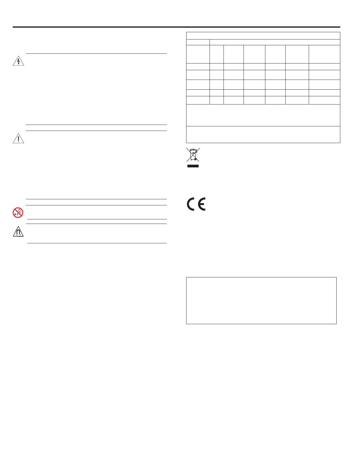
Names and Contents of Toxic or Hazardous Substances or Elements
Toxic or Hazardous Substances and Elements
Part
Name
Lead
(Pb)
Mercury
(Hg)
Cadmium
(Cd)
Hexava-
lent
(CR(VI))
Polybro-
minated
Biphenyl
(PBB)
Polybro-
minated
diphenylether
(PBDE)
PCBs
X O O O O O
Metal
parts
X O O O O O
Plastic
parts
O O O O O O
Speakers
X O O O O O
Cables
X O O O O O
This table is prepared in accordance with the provisions of SJ/T 11364.
O: Indicates that this toxic or hazardous substance contained in all of the
homogeneous materials for this part is below the limit requirement of GB/T
26572.
X: Indicates that this toxic or hazardous substance contained in at least one of
the homogeneous materials used for this part is above the limit requirement of
GB/T 26572
This symbol means the product must not be discarded as
household waste, and should be delivered to an appropriate
collection facility for recycling. Proper disposal and recycling
helps protect natural resources, human health and the
environment. For more information on disposal and
recycling of this product, contact your local municipality,
disposal service, or the shop where you bought
this product.
Bose Corporation hereby declares that this product is in
compliance with the essential requirements and other
relevant provisions of Directive 1999/5/EC and all other
applicable EU directive requirements. The complete
declaration of conformity can be found at:
www.Bose.com/compliance
China Importer: Bose Electronics (Shanghai) Company Limited, Part
C, Plan 9, No. 353 North Riying Road, China (Shanghai) Pilot Free
Trade Zone
EU Importer: Bose Products B.V., Gorslaan 60, 1441 RG Purmerend,
The Netherlands
Taiwan Importer:
Bose Taiwan Branch, Room 905, 9F, Worldwide
House, 131 Min Sheng East Rd, Section 3, Taipei, Taiwan, 105
Please complete and retain for your records:
Model number: _____________________________________________
Serial number: _____________________________________________
Purchase date: _____________________________________________
We suggest you keep your receipt with this owner’s guide.
Date of manufacture:
The first bolded digit in the serial number indicates the year of manu-
facture; “5” is 2005 or 2015.
VIRTUALLY INVISIBLE is a registered trademark of Bose Corporation in the U.S. and other countries.
© 2017 Bose Corporation. No part of this work may be reproduced, modified, distributed, or otherwise used without prior written permission.
2 - English
English - 3
Contents
Introduction
About your Virtually Invisible
®
791 series II or 591 in-ceiling speakers .................................................................................................................. 4
Unpacking ......................................................................................................................................................................................................................... 4
Recommended tools ............................................................................................................................................................................................... 4
Speaker wire requirements............................................................................................................................................................................................. 4
Placement guidelines ...................................................................................................................................................................................................... 4
Placement in unfinished construction ................................................................................................................................................................. 4
Installing the Speakers
Cutting the speaker hole ................................................................................................................................................................................................. 5
Connecting the speaker wire .......................................................................................................................................................................................... 5
Installing the speaker ...................................................................................................................................................................................................... 6
Attaching the grille .................................................................................................................................................................................................. 6
Care and Maintenance
Troubleshooting ............................................................................................................................................................................................................... 7
Accessories ........................................................................................................................................................................................................................ 7
Customer service .............................................................................................................................................................................................................. 7
Limited warranty .............................................................................................................................................................................................................. 7
Technical information ...................................................................................................................................................................................................... 7
4 - English
About your Virtually Invisible
®
791
series II or 591 in-ceiling speakers
The Bose
®
Virtually Invisible
®
791 series II or 591 in-ceiling
speakers provide s uperior performance for built-in stereo
music listening and home theater enjoyment.
Unpacking
Carefully unpack the carton and confirm that the following
parts are included:
Virtually Invisible
®
791
series II speakers
Virtually Invisible
®
591
speakers
Two speakers Two speakers
Two speaker grilles Two speaker grilles
Template Template
Note: If part of the system is damaged, do not use it. Contact
your authorized Bose
®
dealer or Bose customer service.
Refer to the contact sheet in the carton.
Recommended tools
You may need the following tools to complete installation:
Phillips-head screwdriver Cutting tool
Power drill Safety goggles
Speaker wire requirements
Gauge Maximum Length
18 AWG (0.82 mm
2
) 20 ft. (6 m)
16 AWG (1.3 mm
2
) 30 ft. (9 m)
14 AWG (2.1 mm
2
) 50 ft. (15 m)
12 AWG (3.3 mm
2
) 90 ft. (27 m)
Allow enough wire from the ceiling to wire the speakers
before installing.
Strip ½ in. (13 mm) of insulation at each end of both wires.
Please check your local building codes and use only the
correct type of wire required for in-ceiling installation.
For information on installing speaker wire, consult a
professional electrician or audio/video installer.
Placement guidelines
For optimal stereo performance, install the speakers in
positions similar to the diagram below at a minimum of the
suggested distances:
Notes:
Use a stud finder to ensure the speaker hole is at least 4¾
in. (12 cm) away from a joist.
Mount these speakers in wood frame or similar construction
only. Bose recommends installing these speakers only in
wood frame or similar construction with adequately spaced
studs, as found in 2 x 6 construction.
Placement in unfinished construction
If you are planning installation in unfinished construction,
purchase the Bose rough in kit. See “Accessories” on page
7.
Introduction
> 6 ft. (2 m)
> 2 ft.
(.6 m)
> 3 ft.
(1 m)
> 3 ft.
(1 m)
> 2 ft.
(.6 m)
> 2 ft.
(.6 m)
> 2 ft.
(.6 m)
English - 5
Installing the Speakers
Cutting the speaker hole
1. Trace the template in the speaker location.
WARNING: Do not cut into surfaces that have hazards
concealed behind them such as electrical
wiring or plumbing. If you are unsure of
your ability to mount this speaker, contact a
professional installer.
2. Drill a hole inside the template area large enough for your
cutting tool.
3. Cut along the line you traced.
4. Remove the cutout section.
5. Clear away any torn or rough material from around
the hole.
Connecting the speaker wire
1. Pull out at least 14 in. (36 cm) of the speaker wire.
Allow enough wire to connect the speaker from where you
are standing.
2. Connect the positive wire to the red marked terminal on
the speaker.
Note: The terminal marking is located on the top of
the terminal.
Virtually Invisible
®
591 speaker
3. Connect the negative wire to the black marked terminal on
the speaker.
Red (positive)
marking
6 - English
Installing the speaker
1. Holding the outside edges, insert the speaker into
the hole.
Note: Do not press on the two small drivers on the face of
the speaker. This may damage the speaker.
Virtually Invisible
®
591 speaker
CAUTION:
Certain forms of insulation (such as horse
hair plaster, newspaper, cellulose, or blown-in
materials) may pose a risk of ignition. Be sure
to keep all insulation away from the speakers.
2. Tighten all the clamp screws with a Phillips
head screwdriver.
Note: If using a power drill, choose the lowest
torque setting.
Virtually Invisible
®
591 speaker
Attaching the grille
The grille magnetically attaches to the rim of the speaker.
Place the grille on speaker.
Virtually Invisible
®
591 speaker
Painting the grille
You can paint the speaker grilles before you attach them to the
speaker. Bose
®
is not responsible for the quality of adhesion or
finish of non-factory-applied paints.
Latex or oil-based architectural paint requires thinning for
use with a siphon-feed spray gun. Refer to the owner’s guide
provided with your spray gun for guidelines.
Be careful when using a sharp implement in the grille
perforations to remove a paint clog, which can damage
the grille.
Installing the Speakers
English - 7
Care and Maintenance
Troubleshooting
Problem What to do
No sound
from
speakers
Ensure the speaker wires did not
disconnect from the speakers or the
receiver/amplifier.
Check the settings on your receiver/amplifier.
Refer to the receiver/amplifier owner’s guide for
instructions on settings.
If other stereo speakers are connected to a
second set of audio outputs on your receiver/
amplifier, select the proper A or B speaker setting
to match the A or B outputs connected to your
speakers.
Sound from
one speaker
only
Center the balance control on your receiver/
amplifier.
Ensure no wires from the positive and negative
terminals on the receiver/amplifier are touching.
Disconnect the speaker wire from the receiver/
amplifier channel and reconnect it to a different
channel.
Check that no wires from the positive and negative
terminals are touching where the speaker wire
connects to the speaker.
Disconnect the speaker wire from the speaker and
reconnect it to another speaker. If this speaker
works, your speaker needs to be serviced. Refer
to the contact sheet in the carton.
Replace and re-install the speaker wire if these
troubleshooting steps do not solve the problem.
Bass/treble
is weak
Adjust the tonal balance setting on your
receiver/amplifier.
Ensure there are no gaps between the speaker
frame and the wall surface.
Switch the wires connected to the positive and
negative terminals on the receiver/amplifier.
Disconnect the speaker wire from the receiver/
amplifier channel and reconnect it to a
different channel.
Static/noise
from speaker
Ensure the wires are in good condition, are firmly
connected to the speaker and receiver/amplifier
and are not touching across terminals.
Connect the music source to the
receiver/amplifier properly.
See “Sound from one speaker only”.
Accessories
For unfinished construction, use the Bose
®
rough-in kit.
The kit contains parts for two speakers and is designed for
installation after the joists are in place and before wallboard
is added. When installed, the kit reserves a place for each
speaker and indicates where to make the speaker hole in the
wallboard.
For more information or to order accessories, contact Bose
customer service. Refer to the contact sheet in the carton.
Customer service
For additional help using the system:
Visit owners.Bose.com
Contact Bose Customer Service. Refer to the contact sheet
in the carton.
Limited warranty
Your system is covered by a limited warranty. Details of the
limited warranty are provided on the product registration card
that is in the carton. Please refer to the card for instructions on
how to register. Failure to register will not affect your limited
warranty rights.
The warranty information provided with this product does not
apply in Australia and New Zealand. See our website at
www.Bose.com.au/warranty or www.Bose.co.nz/warranty for
details of the Australia and New Zealand warranty.
Technical information
Compatibility
Compatible with amplifiers or receivers rated
10-100W per channel/rated 4 to 8 ohms
Virtually Invisible
®
791 series II: 50W IEC continuous power
handling; rated 6 ohms
Virtually Invisible
®
591: 50W IEC continuous power handling;
rated 8 ohms
Virtually Invisible
®
791 series II driver complement:
Two 1" (25.4 mm) dome tweeters configured in an array
One 7" (178 mm) high-excursion woofer
Virtually Invisible
®
591 driver complement:
Two
3
4" (19 mm) dome tweeters configured in an array
One 5" (127 mm) high-excursion woofer
Virtually Invisible
®
791 series II dimensions:
Diameter: 8.4" (214 mm)
Depth into ceiling: 4.14" (105.2 mm)
Grille diameter: 10" (254 mm)
Ceiling hole diameter : 8
5
8" (219 mm)
Virtually Invisible
®
591 dimensions:
Diameter: 6.5" (166 mm)
Depth into ceiling: 3.8" (96.7 mm)
Grille diameter: 8.11" (206 mm)
Ceiling hole diameter required: 6.7" (170 mm) diameter
Weight
Virtually Invisible
®
791 series II: 4.8 lb. (2.18 kg) each
Virtually Invisible
®
591: 3.19 lb. (1.45 kg) each
4 - Dansk
Om dine Virtually Invisible
®
791
series II eller 591 loftsindbygede
højttalere
Bose
®
Virtually Invisible
®
791 series II eller 591 loftsindbyggede
højttalere leverer en suveræn præstation til et indbygget
hjemmebiografmiljø, hvor der også kan lyttes til musik i stereo.
Udpakning
Pak omhyggeligt kassen ud, og kontrollér, at følgende dele
er med:
Virtually Invisible
®
791
series II højttalere
Virtually Invisible
®
591
højttalere
To højttalere To højttalere
To højttalerfronter To højttalerfronter
Skabelon Skabelon
Bemærk: Hvis en del af systemet er beskadiget, må du
ikke anvende det. Kontakt din autoriserede
Bose
®
-forhandler eller Boses kundeservice.
Se adresselisten i kassen.
Anbefalede værktøjer
Du får muligvis brug for følgende værktøjer til at afslutte
installationen:
Stjerneskruetrækker Værktøj til skæring
Elektrisk boremaskine Sikkerhedsbriller
Krav til højttalerkabel
Tykkelse Maksimumlængde
0,82 mm
2
6 m
1,3 mm
2
9 m
2,1 mm
2
15 m
3,3 mm
2
27 m
Sørg for, at der er nok ledning fra loftet til at forbinde
højttalerne, før du starter installationen.
Skær 13 mm isolering af i enden på begge ledninger.
Kontroller de lokale bygningsregler for at få oplysninger om
den korrekte type kabel, der kræves ved installation i loftet.
Kontakt en professionel elektriker eller lyd-/videoinstallatør
for at få oplysninger om installation af højttalerkabler.
Retningslinjer for placering
For at få en optimal ydelse i stereo skal højttalerne placeres
på steder, der svarer til nedenstående diagram, og med de
foreslåede afstande som minimum:
Bemærkninger:
Brug en stolpefinder for at sikre, at højttalerhullet er mindst
12 cm væk fra en bjælke.
Monter kun disse højttalere i trælofter eller lignende
konstruktioner. Bose anbefaler, at disse højttalere kun
installeres i trælofter eller en lignende konstruktion med
tilstrækkelig afstand mellem bjælkerne, sådan som de findes
i en 2 x 6-konstruktion.
Placering i en ufærdig konstruktion
Hvis du planlægger en installation i en ufærdig konstruktion,
skal du købe Boses Rough in kit. Se ”Tilbehør” på side 7.
Indledning
> 2 m
> 0,6 m
> 1 m > 1 m
> 0,6 m
> 0,6 m
> 0,6 m
Dansk - 5
Installation af højttalerne
Skæring af højttalerhullet
1. Tegn efter skabelonen ved højttalerens placering.
ADVARSEL: Du må ikke skære i overflader, som har farer
skjult bag dem, såsom elektriske ledninger
eller VVS-installationer. Hvis du tvivler på,
at du er i stand til at udføre denne installation,
kan du kontakte en professionel montør.
2. Bor et hul inde i skabelonområde, der er stort nok til din
skæreværktøj.
3. Skær langs den linje, du har tegnet.
4. Fjern den udskårede del.
5. Fjern alt flosset eller groft materiale omkring hullet.
Tilslutning af højttalerkablet
1. Træk mindst 36 cm af højttalerkablet ud.
Sørg for, at der er nok ledning til at forbinde højttaleren
derfra, hvor du står.
2. Forbind den positive ledning til den røde markerede
terminal på højttaleren.
Bemærk: Terminalens markering findes øverst på
terminalen.
Virtually Invisible
®
591 højttaler
3. Forbind den negative ledning til den sort markerede
terminal på højttaleren.
Rød (positiv)
markering
6 - Dansk
Installation af højttaleren
1. Hold på de udvendige kanter, og sæt højttaleren ind i hullet.
Bemærk: Sørg for ikke at trykke på de små drivere,
der sidder på højttalerens forside. Dette kan
beskadige højttaleren.
Virtually Invisible
®
591 højttaler
FORSIGTIG:
Visse typer isoleringsmateriale (f.eks.
visse typer gips, aviser, cellulose eller
indblæste materialer) kan udgøre en risiko
for antændelse. Sørg for at holde al isolering
væk fra højttalerne.
2. Spænd alle klemmeskruer med en stjerneskruetrækker.
Bemærk: Hvis du bruger en boremaskine, skal du vælge
indstillingen med det laveste moment.
Virtually Invisible
®
591 højttaler
Montering af fronten
Fronten fastsættes magnetisk til kanten på højttaleren.
Placer fronten på højttaleren.
Virtually Invisible
®
591 højttaler
Maling af fronten
Du kan male højttalerfronten, før du fastgør dem til højttaleren.
Bose
®
er ikke ansvarlig for kvaliteten af vedhæftning eller finish
ved brug af maling, der ikke er påført af fabrikken.
Plast- eller oliebaseret vægmaling skal fortyndes for at
kunne bruges med en sprøjtepistol. Se den brugervejledning,
der følger med din sprøjtepistol.
Vær forsigtig, hvis du bruger et skarpt redskab i frontens
perforeringer til at fjerne en klump maling, da dette kan
beskadige fronten.
Installation af højttalerne
Dansk - 7
Pleje og vedligeholdelse
Fejlfinding
Problem Gør følgende
Ingen lyd fra
højttalerne
Kontroller, at højttalerledningerne ikke er
blevet koblet fra højttalerne eller modtageren/
forstærkeren.
Kontroller modtagerens eller forstærkerens
indstillinger. Se brugervejledningen til modtager/
forstærker for at få instruktioner til indstillinger.
Hvis der er tilsluttet andre stereohøjttalere til
et andet sæt lydudgange på forstærkeren/
modtageren, skal du sørge for at vælge den
korrekte A- eller B-højttalerindstilling svarende
til de A- eller B-udgange, der er tilsluttet dine
højttalerne.
Kun lyd fra
den ene
højttaler
Placer modtagerens eller forstærkerens
balanceknap i miderste position.
Sørg for, at ingen ledninger fra de positive og
negative terminaler på modtageren/forstærkeren
rører ved noget.
Kobl højttalerkablet fra modtageren eller
forstærkeren, og slut det til en anden kanal.
Sørg for, at ingen ledninger fra de positive og
negative terminaler på modtageren/forstærkeren
rører ved noget, når højttalerkablet tilsluttes
højttaleren.
Frakobl højttalerkablet fra højttaleren, og slut det
til en anden højttaler. Hvis denne højttaler fungere,
har din højttaler brug for service. Se adresselisten
i kassen.
Udskift og installer højttalerkablet igen, hvis disse
trin til fejlfinding ikke løste problemet.
Bas/diskant
er svag
Tilpas modtagerens/forstærkerens
tonebalanceindstilling.
Sørg for, at der ikke mellemrum mellem
højttalerens ramme og væggen.
Skift kablerne, der er forbundet til de positive og
negative terminaler på modtageren/forstærkeren.
Kobl højttalerkablet fra modtageren eller
forstærkeren, og slut det til en anden kanal.
Statisk/støj
fra højttaleren
Sørg for, at kablerne er i god stand, er fast
forbundet til højttaleren og modtageren/
forstærkeren og ikke rører hinanden mellem
terminalerne.
Tilslut musikkilden til modtageren/forstærkeren
korrekt.
Se ”Kun lyd fra den ene højttaler”.
Tilbehør
Til ufærdige konstruktioner skal du bruge Bose
®
Rough-in Kit.
Dette kit indeholder dele til to højttalere og er designet til
at installeres, efter at loftsbjælkerne på plads, og inden
loftspladerne monteres. Når kittet er installeret, sørger det for
plads til hver af højttalerne og angiver, hvor i loftspladerne
højttalerhullet skal laves.
Kontakt Boses kundeservice for at få oplysninger om bestilling
af tilbehør. Se adresselisten i kassen.
Kundeservice
Yderligere hjælp til at bruge systemet:
Besøg owners.Bose.com
Kontakt Bose Kundeservice. Se adresselisten i kassen.
Begrænset garanti
Dit system er omfattet af en begrænset garanti. Detaljerede
oplysninger om den begrænsede garanti findes på
produktregistreringskortet, som ligger i kassen. Oplysninger
om, hvordan du registrerer, finder du på kortet. Hvis du
undlader at registrere produktet, har det ingen betydning for
den begrænsede garanti.
Garantioplysningerne til dette produkt gælder ikke
for Australien og New Zealand. Se vores websted på
www.Bose.com.au/warranty eller www.Bose.co.nz/warranty for
at få flere oplysninger om garantien i Australien og New Zealand.
Tekniske oplysninger
Kompatibilitet
Kompatible med forstærkere eller modtagere klassificeret til
10-100W pr. kanal/klassificeret til 4 til 8 ohms
Virtually Invisible
®
791 series II: 50W IEC kontinuerlig
strømkapacitet; klassificeret til 6 ohm
Virtually Invisible
®
591: 50W IEC kontinuerlig strømkapacitet;
klassificeret til 8 ohm
Virtually Invisible
®
791 series II driver supplement:
To 25,4 mm dome-diskanthøjtalere konfigureret i et array
En 178 mm bashøjttaler med stor vandring
Virtually Invisible
®
591 driver supplement:
To 19 mm dome-diskanthøjtalere konfigureret i et array
En 127 mm bashøjttaler med stor vandring
Virtually Invisible
®
791 series II dimensioner:
Diameter: 214 mm
Loftsdybde: 105,2 mm
Frontdiameter: 254 mm
Loftshuldiameter : 219 mm
Virtually Invisible
®
591 dimensioner:
Diameter: 166 mm
Loftsdybde: 96,7 mm
Frontdiameter: 206 mm
Diameter i loftshul, der kræves: 170 mm diameter
Vægt
Virtually Invisible
®
791 series II: 2,18 kg for hver
Virtually Invisible
®
591: 1,45 kg for hver
Deutsch - 5
Installieren der Lautsprecher
Aussägen der
Lautsprecheröffnung
1. Zeichnen Sie am vorgesehenen Ort der Lautsprecher eine
Linie um die Schablone.
WARNUNG: Schneiden Sie nicht in Flächen, hinter denen
sich elektrische Leitungen, Rohre oder
ähnliches befinden. Wenn Sie Bedenken bei der
Befestigung der Lautsprecher haben, ziehen
Sie einen qualifizierten Fachbetrieb zu Rate.
2. Bohren Sie in den Schablonenbereich ein Loch, das für Ihr
Schneidwerkzeug groß genug ist.
3. Schneiden Sie entlang der gezeichneten Linie.
4. Entfernen Sie das ausgeschnittene Teil.
5. Beseitigen Sie gerissene oder raue Materialien rund um
die Öffnung.
Anschließen der
Lautsprecherkabel
1. Ziehen Sie mind. 36 cm Lautsprecherkabel heraus.
Lassen Sie genug Kabel übrig, um den Lautsprecher an
Ihrem Standort anzuschließen.
2. Schließen Sie die positive Ader an die rot markierte
Klemme am Lautsprecher an.
Hinweis: Die Klemmenmarkierung befindet sich oben an
der Klemme.
Virtually Invisible
®
591 Lautsprecher
3. Schließen Sie die negative Ader an die schwarz markierte
Klemme am Lautsprecher an.
Rote (positive)
Markierung
Dutch - 3
Inhoud
Inleiding
Over uw Virtually Invisible
®
791 series II- of 591-luidsprekers voor inbouw in het plafond ................................................................................ 4
Uitpakken ........................................................................................................................................................................................................................... 4
Aanbevolen gereedschap ....................................................................................................................................................................................... 4
Vereisten voor luidsprekerdraden ................................................................................................................................................................................. 4
Richtlijnen voor plaatsing ............................................................................................................................................................................................... 4
Plaatsing in een onvoltooide constructie ............................................................................................................................................................ 4
De luidsprekers installeren
Het gat voor de luidspreker uitzagen ........................................................................................................................................................................... 5
De luidsprekerdraad aansluiten ..................................................................................................................................................................................... 5
De luidspreker installeren ............................................................................................................................................................................................... 6
Het rooster bevestigen ........................................................................................................................................................................................... 6
Verzorging en onderhoud
Problemen oplossen ........................................................................................................................................................................................................ 7
Accessoires ........................................................................................................................................................................................................................ 7
Klantenservice .................................................................................................................................................................................................................. 7
Beperkte garantie ............................................................................................................................................................................................................. 7
Technische informatie ..................................................................................................................................................................................................... 7
4 - Dutch
Over uw Virtually Invisible
®
791
series II- of 591-luidsprekers voor
inbouw in het plafond
De Bose
®
Virtually Invisible
®
791- of 591-luidsprekers
voor inbouw in het plafond bieden superieure prestaties
voor het luisteren naar stereomuziek en genieten van een
thuisbioscoopsysteem.
Uitpakken
Pak de doos voorzichtig uit en controleer of de volgende
onderdelen aanwezig zijn:
Virtually Invisible
®
791
series II-luidsprekers
Virtually Invisible
®
591
luidsprekers
Twee luidsprekers Twee luidsprekers
Twee luidsprekerroosters Twee luidsprekerroosters
Sjabloon Sjabloon
Opmerking: Als een onderdeel van het systeem beschadigd
is, mag u dit niet gebruiken. Neem contact
op met uw erkende Bose
®
-dealer of de Bose-
klantenservice. Zie het blad met contactgegevens
in de doos.
Aanbevolen gereedschap
U kunt het volgende gereedschap gebruiken voor de installatie:
Kruiskopschroevendraaier Zaag
Boormachine Veiligheidsbril
Vereisten voor luidsprekerdraden
Dikte Maximumlengte
18 AWG (0,82 mm
2
) 6 m
16 AWG (1,3 mm
2
) 9 m
14 AWG (2,1 mm
2
) 15 m
12 AWG (3,3 mm
2
) 27 m
Zorg vóór de installatie dat er voldoende draad uit het
plafond komt om de luidsprekers aan te sluiten.
Verwijder 13 mm isolatie aan beide uiteinden van beide draden.
Raadpleeg de plaatselijke bouwvoorschriften en gebruik
uitsluitend het juiste type draad voor installatie in het plafond.
Voor informatie over het installeren van luidsprekerdraad
raadpleegt u een professionele elektricien of audio-/video-
installateur.
Richtlijnen voor plaatsing
Voor optimale stereoprestaties installeert u de luidsprekers
in posities als te zien is in het onderstaande schema,
met minimale afstanden als aangegeven:
Opmerkingen:
Gebruik een balkzoeker om te zorgen dat het gat voor de
luidspreker zich op een afstand van ten minste 12 cm van
een balk bevindt.
Monteer deze luidsprekers uitsluitend in een houtskelet-
of vergelijkbare constructie. Bose adviseert om deze
luidsprekers uitsluitend te installeren in een houtskelet- of
vergelijkbare wandconstructie met staanders op voldoende
afstand, zoals in 2x6-constructie.
Plaatsing in een onvoltooide constructie
Als u de luidsprekers wilt installeren in een onvoltooide
constructie, koop dan de Bose-‘rough in kit’. Zie “Accessoires”
op pagina 7.
Inleiding
> 2 m
> 0,6 m
> 1 m > 1 m
> 0,6 m
> 0,6 m
> 0,6 m
Dutch - 5
De luidsprekers installeren
Het gat voor de luidspreker
uitzagen
1. Teken de sjabloon af op de plaats van de luidspreker.
WAARSCHUWING: Zaag niet in oppervlakken waarachter
gevaren verborgen zijn, zoals
elektrische bedrading of water-,
gas- of afvoerleidingen. Als u twijfelt
of u deze luidspreker kunt monteren,
neem dan contact op met een
professionele installateur.
2. Boor een gat binnen het gebied van de sjabloon dat groot
genoeg is voor uw zaag.
3. Zaag langs de lijn die u hebt afgetekend.
4. Verwijder het uitgezaagde deel.
5. Verwijder oneffenheden of rafelig materiaal rond het gat.
De luidsprekerdraad aansluiten
1. Trek minimaal 36 cm van de luidsprekerdraad uit het
plafond.
Zorg dat er genoeg draad is om de luidspreker aan te
sluiten vanaf de plaats waar u staat.
2. Sluit de positieve draad aan op de aansluitklem met een
rode markering op de luidspreker.
Opmerking: De markering van de aansluitklem bevindt
zich aan de bovenkant van de aansluitklem.
Virtually Invisible
®
591-luidspreker
3. Sluit de negatieve draad aan op de aansluitklem met een
zwarte markering op de luidspreker.
Rode (positieve)
markering
6 - Dutch
De luidspreker installeren
1. Houd de buitenste randen van de luidspreker vast en
breng deze in het gat in.
Opmerking: Druk niet op de twee kleine drivers aan de
voorkant van de luidspreker. Hierdoor kan de
luidspreker worden beschadigd.
Virtually Invisible
®
591-luidspreker
LET OP:
Bepaalde soorten isolatie (zoals pleister met
paardenhaar, kranten, cellulose of ingespoten
materiaal) kunnen ontbrandingsgevaar
opleveren. Zorg dat u alle isolatie weghoudt van
de luidsprekers.
2. Draai alle klemschroeven aan met een
kruiskopschroevendraaier.
Opmerking: Als u een boormachine gebruikt, kies dan de
laagste torsie-instelling.
Virtually Invisible
®
591-luidspreker
Het rooster bevestigen
Het rooster wordt magnetisch aan de rand van de
luidspreker bevestigd.
Plaats het rooster op de luidspreker.
Virtually Invisible
®
591-luidspreker
Het rooster verven
U kunt de luidsprekerroosters verven voordat u deze aan de
luidspreker bevestigt. Bose
®
is niet verantwoordelijk voor
de kwaliteit van adhesie of afwerking van niet in de fabriek
aangebrachte verf.
Als u verf op basis van latex of olie gebruikt, moet u de verf
verdunnen als u een verfspuit gebruikt. Raadpleeg voor
richtlijnen de handleiding die is bijgeleverd bij uw verfspuit.
Wees voorzichtig bij het gebruik van een scherp instrument
in de perforaties van het rooster om verf te verwijderen,
aangezien dit kan leiden tot schade aan het rooster.
De luidsprekers installeren
Dutch - 7
Verzorging en onderhoud
Problemen oplossen
Probleem Wat te doen
Geen geluid
uit de
luidsprekers
Controleer of de luidsprekerdraden niet zijn
losgeraakt van de luidsprekers of de receiver/
versterker.
Controleer de instellingen van de receiver/
versterker. Raadpleeg de gebruikershandleiding
van de receiver/versterker voor aanwijzingen voor
instellingen.
Als er andere stereoluidsprekers worden
aangesloten op een tweede set audio-uitgangen
op uw receiver/versterker, selecteer dan de juiste
instelling voor luidspreker A of B zodat deze
overeenkomt met de uitgangen A of B die zijn
aangesloten op uw luidsprekers.
Geluid uit
slechts één
luidspreker
Centreer de balansregeling van de receiver/
versterker.
Zorg dat de draden van de positieve en negatieve
aansluitklemmen op de receiver/versterker elkaar
niet raken.
Koppel de luidsprekerdraad los van het receiver-/
versterkerkanaal en sluit deze opnieuw aan op een
ander kanaal.
Controleer of de draden van de positieve en
negatieve aansluitklemmen elkaar niet raken
op het punt waar de luidsprekerdraad op de
luidspreker is aangesloten.
Koppel de luidsprekerdraad los van de luidspreker
en sluit deze opnieuw aan op een andere
luidspreker. Als deze luidspreker werkt, moet uw
luidspreker mogelijk worden gerepareerd. Zie het
blad met contactgegevens in de doos.
Als het probleem met deze stappen niet wordt
opgelost, vervang dan de luidsprekerdraad en
installeer deze opnieuw.
Zwakke lage/
hoge tonen
Stel de toonbalansinstelling op uw receiver/
versterker bij.
Zorg dat er geen spleten zitten tussen het
luidsprekerframe en het muuroppervlak.
Wissel de draden om die zijn aangesloten op de
positieve en negatieve aansluitklemmen op de
receiver/versterker.
Koppel de luidsprekerdraad los van het receiver-/
versterkerkanaal en sluit deze opnieuw aan op een
ander kanaal.
Storing/
ruis van
luidspreker
Zorg dat alle draden in goede staat verkeren,
stevig zijn aangesloten op de luidspreker en
receiver/versterker en elkaar niet raken tussen de
aansluitklemmen.
Sluit de muziekbron goed op de receiver/
versterker aan.
Zie “Geluid uit slechts één luidspreker”.
Accessoires
Voor onvoltooide constructies gebruikt u de Bose
®
-‘rough-in kit’.
De kit bevat onderdelen voor twee luidsprekers en is
ontworpen voor installatie nadat de balken zijn geplaatst en
voordat wandplaten zijn toegevoegd. Na installatie houdt de
kit ruimte vrij voor elke luidspreker en geeft deze aan waar de
gaten in de wandplaten moeten komen.
Voor meer informatie of voor het bestellen van accessoires
neemt u contact op met de Bose-klantenservice. Zie het blad
met contactgegevens in de doos.
Klantenservice
Voor verdere hulp bij gebruik van het systeem:
Ga naar owners.Bose.com
Neem contact op met de Bose-klantenservice. Zie het blad
met contactgegevens in de doos.
Beperkte garantie
Voor uw systeem geldt een beperkte garantie. Informatie
over de beperkte garantie wordt vermeld op de
productregistratiekaart in de doos. Zie de kaart voor informatie
over hoe u het product registreert. Als u het product niet
registreert, is dit niet van invloed op uw rechten onder de
beperkte garantie.
De bij dit product verstrekte garantie-informatie is niet van
toepassing in Australië en Nieuw-Zeeland. Zie onze website op
www.Bose.com.au/warranty of www.Bose.co.nz/warranty voor
informatie over de garantie voor Australië en Nieuw-Zeeland.
Technische informatie
Compatibiliteit
Compatibel met versterkers of receivers van
10-100 W per kanaal/geschikt voor 4 tot 8 ohm
Virtually Invisible
®
791 series II: 50 W IEC voortdurende
belastbaarheid; 6 ohm
Virtually Invisible
®
591: 50 W IEC voortdurende belastbaarheid;
8 ohm
Virtually Invisible
®
791 series II-drivers:
Twee koepeltweeters van 25,4 mm geconfigureerd in een array
Eén woofer van 178 mm met hoge uitslag
Virtually Invisible
®
591-drivers:
Twee koepeltweeters van 19 mm geconfigureerd in een array
Eén woofer van 127 mm met hoge uitslag
Afmetingen van de Virtually Invisible
®
791 series II:
Diameter: 214 mm
Diepte in plafond: 105,2 mm
Diameter van het rooster: 254 mm
Diameter van het gat in het plafond: 219 mm
Afmetingen van de Virtually Invisible
®
591:
Diameter: 166 mm
Diepte in plafond: 96,7 mm
Diameter van het rooster: 206 mm
Benodigde diameter van het gat in het plafond: 170 mm
Gewicht
Virtually Invisible
®
791 series II: 2,18 kg per stuk
Virtually Invisible
®
591: 1,45 kg per stuk
4 - Español
Acerca de los altavoces de techo
Virtually Invisible
®
791 serie II o 591
Los altavoces de techo Bose
®
Virtually Invisible
®
791 serie
II o 591 brindan un desempeño s uperior para la escucha de
música estéreo integrada.
Desembalar
Desembale cuidadosamente la caja y confirme que estén
incluidas las siguientes partes:
Altavoces Virtually
Invisible
®
791 Serie II
Altavoces Virtually
Invisible
®
591
Dos altavoces Dos altavoces
Dos rejillas de altavoz Dos rejillas de altavoz
Plantilla Plantilla
Nota: Si parte del sistema está dañado, no lo use.
Comuníquese con un representante autorizado de Bose
®
o al Servicio de atención al cliente de Bose. Remítase a
la hoja de contacto que se encuentra en la caja.
Herramientas recomendadas
Es posible que necesite las siguientes herramientas para
completar la instalación:
Destornillador tipo Phillips Herramienta de corte
Taladro Antiparras de seguridad
Requisitos de los cables de altavoz
Calibre Longitud máxima
18 AWG (0,82 mm
2
) 20 pies (6 m)
16 AWG (1,3 mm
2
) 30 pies (9 m)
14 AWG (2,1 mm
2
) 50 pies (15 m)
12 AWG (3,3 mm
2
) 90 pies (27 m)
Verifique que tenga suficiente cable del techo para conectar
los altavoces antes de instalarlos.
Tira de 13 mm de material aislante a cada extremo de
ambos cables.
Consulte los códigos de edificación local y solo use el tipo
correcto de cable que se necesita para las instalaciones en
el techo.
Para información sobre cómo instalar el cable de altavoz,
consulte un electricista profesional o instalador de audio/video.
Pautas de colocación
Para un óptimo desempeño estéreo, instale los altavoces en
posiciones similares al siguiente diagrama a un mínimo de las
distancias sugeridas:
Notas:
Use un detector de vigas para asegurarse de que el agujero
para el altavoz se encuentra al menos a 12cm de distancia
de una viga.
Monte los altavoces solo en un marco de madera o
construcción similar. Bose recomienda instalar estos
altavoces solo en un marco de madera o construcción
similar con vigas adecuadamente espaciadas, como en una
construcción 2 x 6.
Ubicación en una construcción sin terminar
Si planea instalarlos en un construcción sin terminar, adquiera
el equipo de instalación de Bose. Vea “Accesorios” en la
página 7.
Introducción
> 6 pies (2 m)
> 2 pies
(6 m)
> 3 pies
(1 m)
> 3 pies
(1 m)
> 2 pies
(6 m)
> 2 pies
(6 m)
> 2 pies
(6 m)
Español - 5
Instalación de los altavoces
Agujero para los altavoces
1. Marque la plantilla en la ubicación de los altavoces.
ADVERTENCIA: No los monte sobre una superficie que
no sea lo suficientemente estable, o que
pueda presentar peligro como cables
de electricidad o cañerías. Si no está
seguro de cómo montar los altavoces,
contacte a un instalador profesional.
2. Perfore un agujero en el área de la plantilla lo
suficientemente grande para la herramienta de corte.
3. Corte a lo largo de la línea trazada.
4. Quite la sección cortada.
5. Lije los bordes del agujero.
Conexión del cable de altavoz
1. Saque por lo menos 36 cm del cable de altavoz.
Tenga suficiente cable para conectar el altavoz desde la
distancia seleccionada.
2. Conecte el cable positivo al terminal de color rojo en
el altavoz.
Nota: El color del terminal se encuentra en la parte
superior del terminal.
Altavoz Virtually Invisible
®
591
3. Conecte el cable negativo al terminal de color negro en
el altavoz.
Marca roja
(positivo)
Finnish - 5
Kaiuttimien asentaminen
Aukon sahaaminen kaiutinta varten
1. Jäljennä malli kaiuttimen paikalle.
VAARA: Älä sahaa pintoja, joiden takana voi olla sähkö-
tai vesijohtoja tai muita rakenteita, jotka eivät saa
vaurioitua. Jos olet epävarma asennustaidoistasi,
ota yhteys ammattiasentajaan.
2. Poraa mallin alueelle sahaustyökalulle sopiva aukko.
3. Sahaa piirtämääsi viivaa pitkin.
4. Irrota sahattu osa.
5. Puhdista repeytymät aukon ympäriltä.
Kaiutinjohdon liittäminen
1. Vedä ulos vähintään 36 cm kaiutinjohtoa.
Johdon tulee ulottua reilusti seisomapaikasta kaiuttimen
liittämiskohtaan.
2. Liitä positiivinen johdin kaiuttimen punaisella merkittyyn
liitäntään.
Huomautus: Liitännän merkintä on sen yläosassa.
Virtually Invisible
®
591 -kaiutin
3. Liitä negatiivinen johdin kaiuttimen mustalla merkittyyn
liitäntään.
Punainen
(positiivinen)
merkintä
  • Page 1 1
  • Page 2 2
  • Page 3 3
  • Page 4 4
  • Page 5 5
  • Page 6 6
  • Page 7 7
  • Page 8 8
  • Page 9 9
  • Page 10 10
  • Page 11 11
  • Page 12 12
  • Page 13 13
  • Page 14 14
  • Page 15 15
  • Page 16 16
  • Page 17 17
  • Page 18 18
  • Page 19 19
  • Page 20 20
  • Page 21 21
  • Page 22 22
  • Page 23 23
  • Page 24 24
  • Page 25 25
  • Page 26 26
  • Page 27 27
  • Page 28 28
  • Page 29 29
  • Page 30 30
  • Page 31 31
  • Page 32 32
  • Page 33 33
  • Page 34 34
  • Page 35 35
  • Page 36 36
  • Page 37 37
  • Page 38 38
  • Page 39 39
  • Page 40 40
  • Page 41 41
  • Page 42 42
  • Page 43 43
  • Page 44 44
  • Page 45 45
  • Page 46 46
  • Page 47 47
  • Page 48 48
  • Page 49 49
  • Page 50 50
  • Page 51 51
  • Page 52 52
  • Page 53 53
  • Page 54 54
  • Page 55 55
  • Page 56 56
  • Page 57 57
  • Page 58 58
  • Page 59 59
  • Page 60 60
  • Page 61 61
  • Page 62 62
  • Page 63 63
  • Page 64 64
  • Page 65 65
  • Page 66 66
  • Page 67 67
  • Page 68 68
  • Page 69 69
  • Page 70 70
  • Page 71 71
  • Page 72 72
  • Page 73 73
  • Page 74 74
  • Page 75 75
  • Page 76 76
  • Page 77 77
  • Page 78 78
  • Page 79 79
  • Page 80 80
  • Page 81 81
  • Page 82 82
  • Page 83 83
  • Page 84 84
  • Page 85 85
  • Page 86 86
  • Page 87 87
  • Page 88 88
  • Page 89 89
  • Page 90 90
  • Page 91 91
  • Page 92 92
  • Page 93 93
  • Page 94 94
  • Page 95 95
  • Page 96 96
  • Page 97 97
  • Page 98 98
  • Page 99 99
  • Page 100 100
  • Page 101 101
  • Page 102 102
  • Page 103 103
  • Page 104 104
  • Page 105 105
  • Page 106 106
  • Page 107 107
  • Page 108 108
  • Page 109 109
  • Page 110 110
  • Page 111 111
  • Page 112 112
  • Page 113 113
  • Page 114 114
  • Page 115 115
  • Page 116 116

Bose MediaMate® computer speakers Owner's manual

Category
Loudspeakers
Type
Owner's manual

Ask a question and I''ll find the answer in the document

Finding information in a document is now easier with AI