◦ Hydraulic fluid
Mounting Considerations
NOTICE
The pump must be installed in a dry location, protected from
water and the weather.
• Before you start the pump installation, you must identify the
type of hydraulic steering system in your boat and consult the
hydraulic diagrams. Each boat is different, and you must
consider the existing hydraulic layout before deciding where
to mount the pump (Hydraulic Considerations, page 2).
• You should mount the pump horizontally, if possible.
• If you cannot mount the pump horizontally, you must mount it
vertically with the pump head connectors facing up.
• You must mount the pump in a location to which you can
extend the hydraulic steering lines of the boat.
• The pump has five hydraulic-connector fittings, although only
three are used when installing the pump as recommended.
The pump-valve illustration provided in these instructions
may be helpful when determining the fitting layout that is best
for your installation location (Pump Ports and Valves,
page 2).
Mounting the Pump
Before you mount the pump, if your boat has an unbalanced
cylinder steering system, you must re-configure the pump to
work properly with the unbalanced cylinder (Configuring the
Pump for an Unbalanced Cylinder, page 5).
Before you can mount the pump, you must select a location
(Mounting Considerations, page 2) and determine the correct
mounting hardware (Tools Needed, page 1).
1
Hold the pump in the intended mounting location and mark
the locations of the mounting holes on the mounting surface,
using the pump as a template.
2
Using a drill bit appropriate for the mounting surface and
selected mounting hardware, drill the four holes through the
mounting surface.
3
Secure the pump to the mounting surface using the selected
mounting hardware.
Hydraulic Considerations
NOTICE
When adding hydraulic line to the system, use only hose with
machine-crimped or field-replaceable fittings that have a
minimum rating of 1000 lbf/in² (6,895 kPa).
You must not use Teflon
®
tape or thread putty on any hydraulic
fitting in this system. Small debris from Teflon tape or thread
putty can enter the hydraulic system, become stuck in valves,
and render the autopilot or steering system inoperable. Using
Teflon tape or thread putty on any hydraulic fitting in this system
voids your warranty.
Use caution when applying liquid thread sealant to avoid
damage to the hydraulic system or to the autopilot system.
Do not attempt to use the autopilot to steer the boat until you
bleed all air from each part of the hydraulic system.
Consult the hydraulic-layout diagrams to help determine how to
best install the pump in the hydraulic system of the boat
(Hydraulic Layouts, page 3).
When planning the hydraulic layout and making all hydraulic
connections, consider the following:
• The pump must be reconfigured if the boat is equipped with
an unbalanced steering cylinder (Configuring the Pump for an
Unbalanced Cylinder, page 5).
• The size and thread types for the hydraulic ports on the pump
are listed in the specifications (Port and Fitting Specifications,
page 5).
• You should use T-connectors (not included) to connect the
hydraulic lines to the pump.
• You should install shut-off valves (not included) in the
hydraulic lines between the pump manifold and T-connectors
to allow for easy pump isolation and removal.
• For hydraulic fittings with an O-ring, such as ORB and ORFS
fittings, you should not use thread sealant.
• For hydraulic fittings without an O-ring, you should use a
liquid thread sealant, such as Loctite 567.
• When using liquid thread sealant, you must follow the
instructions regarding the cure time, for example, Loctite 567
cures after four hours. If the thread sealant is not properly
cured per the manufacturer's instructions, the high pressure
in the hydraulic lines may push the sealant out of the threads
and create a leak.
• When disconnecting a connector sealed with liquid sealant,
you must take care to keep any slivers or other debris from
the cured sealant from entering the hydraulic system.
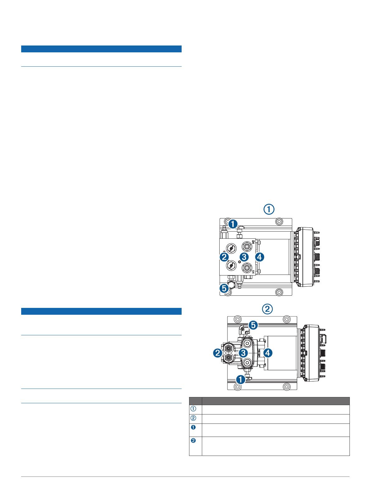
Pump Ports and Valves
The two styles of pump that may be included as part of your
autopilot kit use similar port configurations. Use the diagrams
and table below when planning your pump hydraulic
connections.
Item Description
SmartPump
SmartPump v2
Bypass valve. Used for hydraulic bleeding only, and must remain
fully tightened during normal operation.
Check valves. Must be reconfigured if the boat is equipped with
an unbalanced cylinder (Configuring the Pump for an Unbalanced
Cylinder, page 5).
2


