D660-0084(-BLK) Installation Instructions
Installation Instructions
D660-0084
and
D660-0084-BLK
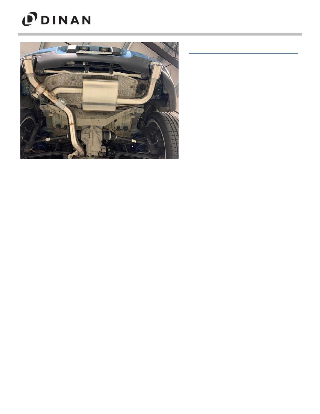
EXHAUST SYSTEM
Vehicle Application List:
2017-2021 F54 MINI Clubman S ALL4
2017-2021 F60 MINI Countryman S ALL4
Document Revision: B
Release Date: February 17, 2023
Contents
Parts List ......................................... 2
Removal: Stock System ........................ 3
Assembly: Valve Brackets/Motor ............. 4
Installation: ...................................... 6
Inlet Tube ..................................... 6
Axle Back ...................................... 7
Exhaust Tips ................................... 9
Exhaust Adjustment ......................... 10
Clamp Torque Settings ..................... 10
Appendix: ....................................... 11
Wiring Valve for F60 ........................ 11
Wiring Valve for F54 ........................ 17
Final Installation ............................ 20
Thank you for being selective enough to choose a Dinan
Performance Exhaust System. The Dinan Engineering Team
has spent many hours developing this product to assure that
you will receive increased performance, durability and an
aesthetic design that you as a customer will be able to enjoy
for many years. Ease of installation and maintenance is
important to us and has been highly considered throughout
the design process.
Prior to performing the installation, familiarize yourself with
these instructions as it should help you with the process. If
you feel that you do not have the required skills or tools,
please arrange for a qualified repair facility to perform the
installation.
If you have any difficulties during the installation, or if these
instructions are not clear to you, please call Dinan's Technical
Support Staff at (800) 341-5480.
Again, thank you for choosing Dinan. Enjoy.


