User guide Danfoss Air ventilation units
© Danfoss | HydronicS | Sub-systems | 2023.10 | 8
BC465345765623en-010101
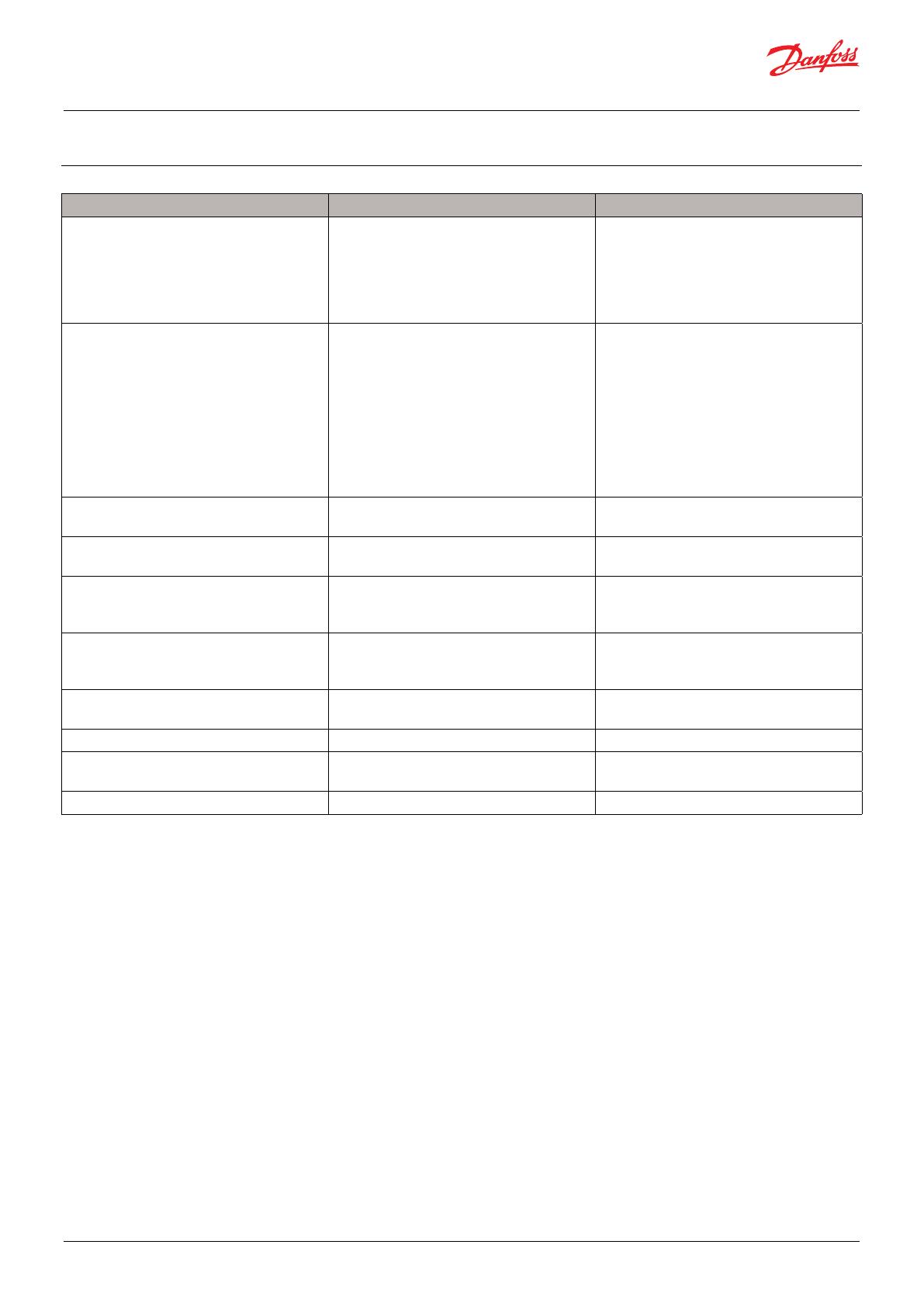
5 ERROR MESSAGE
Alarm Reason Handling
Yellow LED (30 /min.) and beep sound.
The unit continues to run, but with ad-
ditional power consumption and possible
noise nuisance due to increased pressure
loss in the dirty lter.
Filters are in need of replacement Change the lters and reset the lter timer
on the unit.
Red ashing LED (30/min.) and beep sound.
The unit continues to run in fail-safe mode,
with the supply air fan constantly run-
ning at the lowest speed (stage 1) and the
extract air fan constantly running at stage
1 or 2.
One of the following components is faulty
or has a poor connection:
• T3 extraction sensor
• T4 return sensor
Or
One of the two fans is not reaching the
desired speed.
Inspect and replace the sensor kit if neces-
sary.
Check if the fans run smoothly and if the
wires have lost their connection.
The unit is not running and there is no light
in the control panel
The power is disconnected. Check that the power cable is tted cor-
rectly.
There is water around/under the unit A water trap has not been installed on the
drain as prescribed.
Check and install the water trap as pre-
scribed.
The drain nozzle on the aggrega or the
drain hose is frozen.
Install frost protection from the drain spout
of the unit all the way to the drain, possibly
using a heating cable (accessory).
The drain is blocked in the hose or in the
drip tray inside the unit.
Check that the drain is not blocked and
clean with water and washing-up liquid if
necessary.
The unit makes abnormal noise Fan level 4 is running (only intended to run
for a short period of time)
Turn the unit down to level 1, 2, 3 or acti-
vate automatic demand control.
The lter is blocked. Check and change the lter if necessary
The airway may be partially blocked Check that air inlets and ducts are not
blocked by external elements.
The unit is not regulated correctly. Make sure the unit is properly registered.


