Tekelek 4G NB-IoT, CAT-M1 LTE Pressure Logger Installation guide

Type
Installation guide

Tekelek 4G NB-IoT, CAT-M1 LTE Pressure Logger is a multipurpose data logger that communicates data to a remote server for monitoring fuel tank levels and flow rates. It features ATEX certification for use in hazardous environments and offers various mounting options for easy installation. The logger comes with a pressure sensor cable that should be installed facing downwards. It has a vent plug to equalize internal and external pressure and an M4 stud connection for equipotential grounding.

Tekelek 4G NB-IoT, CAT-M1 LTE Pressure Logger is a multipurpose data logger that communicates data to a remote server for monitoring fuel tank levels and flow rates. It features ATEX certification for use in hazardous environments and offers various mounting options for easy installation. The logger comes with a pressure sensor cable that should be installed facing downwards. It has a vent plug to equalize internal and external pressure and an M4 stud connection for equipotential grounding.

1
2
3
LTE Pressure Logger (4G NB-IoT/CAT-M1)
Installation Guide
Thank you for purchasing the Tekelek Pressure Logger 4G NB-IoT/CAT-M1
which is an ATEX certified multipurpose data logger which communicates
data to a remote server, suitable for monitoring fuel tanks levels and flow
rates.
Safety Information:
The Pressure Logger is ATEX compliant, but if installing in a harsh,
environment first check local applicable regulatory and safety
guidelines to ensure installer security. Please refer to the User Manual
for more information on the warnings and hazards.
STEP 1: Installation
The PRESSURE Logger works in conjunction with a remote server and
before installation must first be registered to this. Access to the backend
server is required to verify that the unit has correctly joined the network.
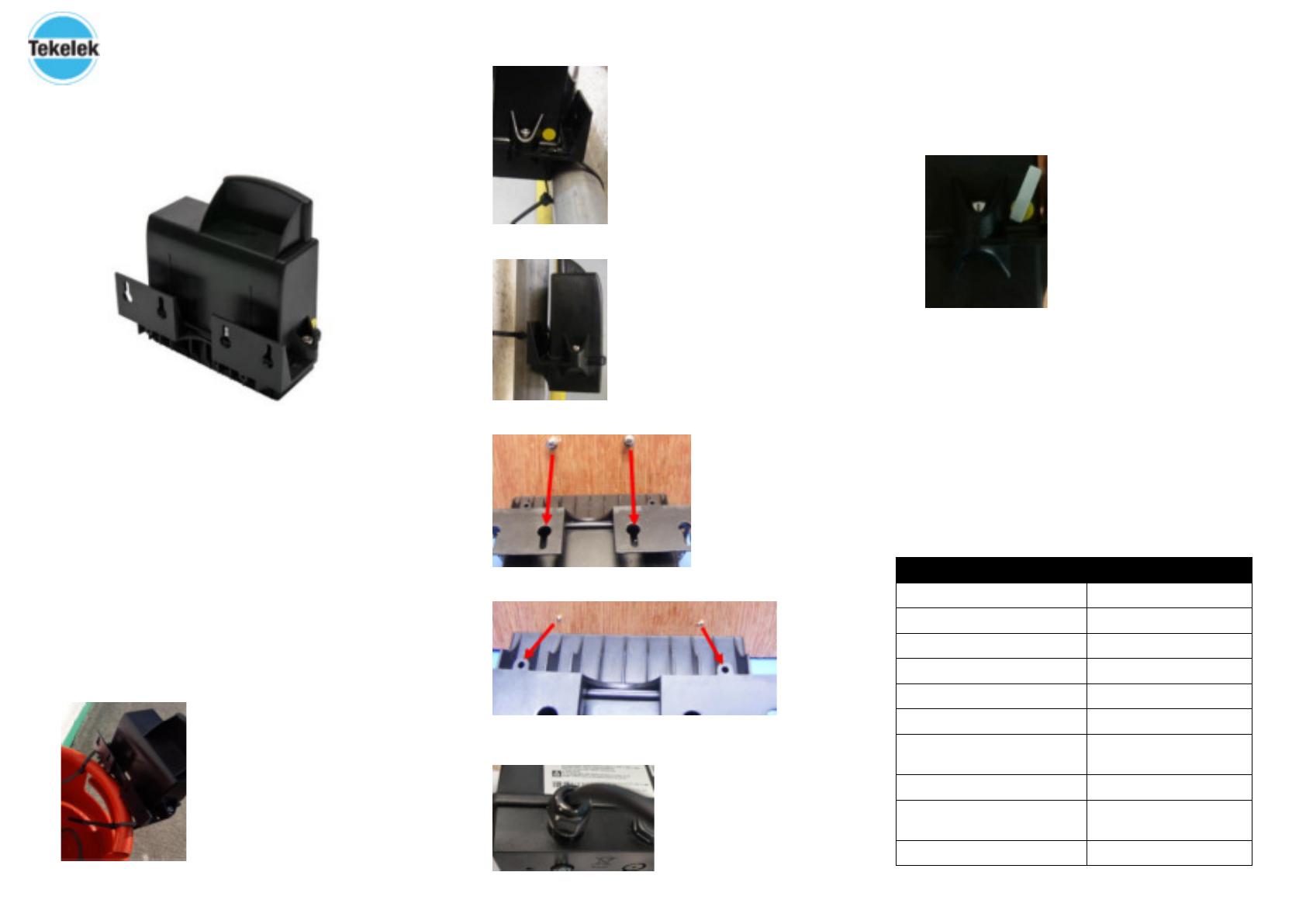
The following outlines the Pressure Logger mounting options. It is
recommended to mount the logger vertically as shown above.
Cable Ties Handle mount:
Cable Ties Horizontal mount onto pipe:
Cable Ties Vertical mount onto pipe:
Screws Wall mount:
Screws Wall mounted from the rear:
The pressure sensor cable should be installed in an orientation facing
downwards.
STEP 2: Activation
Hold the supplied magnet to the indicated hot spot on the Pressure Logger,
4 short beeps will be heard approx. one second apart, these will be
followed be a long beep which indicates that the logger has been activated
and will now attempt to connect to the network.
A series of beeps will be heard. This indicates the logger is registering
onto the network.
Upon successful registration to the network the logger will attempt to
initiate a connection to the server, details of which have been
preconfigured in the logger. This is indicated by higher pitched beeping.
The successful activation of the unit is indicated by two successive short
beeps two seconds apart. Once the logger has successfully connected,
the server must issue the required commands to the logger to
complete the activation process.
STEP 3: Beep Pattern
Beep Pattern
Definition
Low beep once per second
Network Registration
High beep once per second
Network Registration
Low beep once every 4 seconds
Network / TCP Listen
Low beep once every 2 seconds
Re-establish Network / TCP
High / Low combination beep
Incoming Data
Low / High combination beep
Outgoing Data
Low double-beep every 4 seconds
Network Listen
(Data Received & Unit Active)
Low double-beep every 2 seconds
Re-establish Network
High double-beep every 4 seconds
TCP Listen
(Data Received & Unit Active)
High double-beep every 2 seconds
Re-establish TCP
4
5
6
STEP 4: Fitting Pressure Sensor
A 1” or 2” opening is required to fit the pressure gauge. In the
example shown a 2” NPT opening is assumed. Note: other adapter
types are possible - consult factory for further options.
Insert the 2” to 1” NPT adapter. Ensure that it is rightly sealed and
watertight. PTFE tape can be used to ensure a good seal.
The Pressure logger sensor comes fitted with a 1” NPT adapter and a ½”
NPT cord grip cable adapter. The pressure sensor fits through the 1
opening and is placed into the tank.
The 1” adapter is tightened into the 2” adapter and the pressure sensor
lead fed into the tank until the bottom of the sensor is positioned
approximately 50mm above the bottom of the tank. The cable grip is
tightened (torque 1-8 to 2Nm) around the cable to hold it in position.
A connection to the chassis ‘ground’ of the tank is recommended for
equipotential grounding for ATEX applications. An M4 stud
connection is provided ; with an M4 nut and washer to facilitate a
Connection.
The logger has a vent plug to equalise the internal pressure in the
enclosure to the external ambient conditions. For correct operation of
the pressure probe, this vent should not be blocked by immersion in
liquids etc.
An additional application note 9-6111-xx and some instructional videos
can be found on www.tekelek.ie.
For more information on the Tekelek Pressure Logger 4G NB-IoT/CAT-M1
please visit our website www.tekelek.ie where a link to our YouTube page
can also be found.
9-6112-02
  • Page 1 1
  • Page 2 2

Tekelek 4G NB-IoT, CAT-M1 LTE Pressure Logger Installation guide

Type
Installation guide

Tekelek 4G NB-IoT, CAT-M1 LTE Pressure Logger is a multipurpose data logger that communicates data to a remote server for monitoring fuel tank levels and flow rates. It features ATEX certification for use in hazardous environments and offers various mounting options for easy installation. The logger comes with a pressure sensor cable that should be installed facing downwards. It has a vent plug to equalize internal and external pressure and an M4 stud connection for equipotential grounding.

Ask a question and I''ll find the answer in the document

Finding information in a document is now easier with AI