nanoradar NRA24 User manual

Type
User manual

The nanoradar NRA24 is a compact and lightweight K-band radar altimeter with a range of capabilities that make it ideal for use in various applications. With its 2cm measuring accuracy, small size, high sensitivity, and stable performance, the NRA24 is suitable for use in unmanned aircraft systems (UAS), helicopters, small airships, and other fields that require precise altitude measurement. Thanks to its 24GHz-ISM frequency band, it ensures reliable operation while complying with industry standards. The NRA24's compact design (130mm x 70mm x 14.

The nanoradar NRA24 is a compact and lightweight K-band radar altimeter with a range of capabilities that make it ideal for use in various applications. With its 2cm measuring accuracy, small size, high sensitivity, and stable performance, the NRA24 is suitable for use in unmanned aircraft systems (UAS), helicopters, small airships, and other fields that require precise altitude measurement. Thanks to its 24GHz-ISM frequency band, it ensures reliable operation while complying with industry standards. The NRA24's compact design (130mm x 70mm x 14.

NRA24 millimeter wave radar
User manual
(With check sum)
Hunan Nanoradar Science and Technology Co., Ltd.
Disclaimers
Thanks to purchase this product. There is web pages about NRA24 altimeter in our official
website (www.nanoradar.cn).You can find the latest product information and user manual on the
pages. The user manual is subject to change without notice.
Please read this manual carefully before using this product. Once used, it is deemed to have
recognized and accepted the content of this manual. Please strictly follow the manual to install
and use the product. Any improper use may cause damage or injury, and Nanoradar would not
bear the corresponding loss and liability.
Product copyright is retained by Nanoradar. Reproduction in any form shall not be done without
permission. The use of this product and manual shall not be pursued liability for the patent.
Version history
Date
Version
Version description
2017-02-28
2.0
the 2nd version of user manual on NRA24
2017-08-31
2.1
Increase the parity bit in the data load
I
Contents
1 Brief introduction of NRA24................................................................................................................ 1
2 Matters needing attention in use........................................................................................................... 1
3 Shipping list.......................................................................................................................................... 2
4 Quick-to-use steps.................................................................................................................................2
4.1 Pin definition.............................................................................................................................. 2
4.2 Test and use................................................................................................................................ 2
5 Serial-port data parsing......................................................................................................................... 4
5.1 NRA24 configuration (Sensor Configuration)........................................................................... 5
5.2 NRA24 back (Sensor Back)....................................................................................................... 6
5.3 NRA24 system status (Sensor Status)........................................................................................ 7
5.4 Targets output status (Target Status)...........................................................................................8
5.5 Target output information (Target Info)..................................................................................... 8
6 Data parsing examples........................................................................................................................ 10
7 Electrostatic protection....................................................................................................................... 11
7.1 Electrostatic protection measures............................................................................................. 11
7.2 Identification of electrostatic damages..................................................................................... 11
8 Frequently asked questions (FAQ)......................................................................................................11
9 References...........................................................................................................................................12
1
1 Brief introduction of NRA24
NRA24 is compact K-band radar altimeter developed by Hunan Nanoradar Science and
Technology Co., Ltd. It adopts 24GHz-ISM frequency band, with the advantages of 2cm
measuring accuracy, small size, high sensitivity, light weight, easy integration and stable
performance, which satisfies the application requirements in unmanned aircraft system (UAS),
helicopters, small airships and other field.
Dimensions130×70×14.5(mm)
Weight66g(excluding line)
Figure 1 NRA24 outlook
2 Matters needing attention in use
Much attention should be paid to the "matters needing attention".
(1) The power pins shall be connected separately to 5~20V DC stabilized power supply;
(2) Fix the NRA24 with 4 M3 screws.
Any problem in installation, please feel free to contact Nanoradar.
2
3 Shipping list
The shipping list includesNRA24 sensor 1xas in figure 2.
Figure 2 NRA24 delivery physical map
4 Quick-to-use steps
4.1 Pin definition
The definition for NRA24 sensor interface pins are as shown in table1.
Table 1 The definition for NRA24 pin interface
Pin No.
difinition
1
POWER IN(red)
2
GND(black)
3
TTL USART_RX(white)
4
TTL USART_TX(yellow)
4.2 Test and use
NRA24 sensor data can be acquired and parsed by the "MMW Radar general Management
Tool" testing software, which is used to visually display the observation results. The tool is
helpful in the use of NRA24 sensor.
Fast debugging is UART interface debugging method.
First of all, the "millimeter-wave radar general management tool" (PC test software), user
manual shall be provided by Nanoradar. According to the user manual, install and configure the
PC test software.
3
Debugging via UART interface:
1) Test tools and software are as the following table
Table 2 Product test and use tools
No.
Device name
Qty
1
NRA24
1
2
PC
1
3
Serial port adaptor to connect
USB to TTL
1
4
12V power adaptor
1
5
PC test software
1
2) With a USB connection to TTL serial port adaptor, to connect PC and NRA24, as shown in
figure 6 .
Figure 3 Diagram for serial port connection
Note:
Separately supply power from 12V DC stabilized power supply, and do not use 5V power
supply of USB2TTL adapter.
Input voltage range of 5 ~ 20VDC, ripple wave is less than 20mv. Unclean Power supply
will result in the appearance of a number of fixed interference frequency components in the
spectrum during the algorithm analysis, which would have an impact on test results and result in
the continuous target output in a certain fixed distance.
The TX and RX pins of the USB-to-TTL adapter need to be cross-connected to the TX and
RX pins of the NRA24 sensor.
3) USB serial -port adapter is connected to PC. And then open the PC test software to
configure parameters like in figure 4 (plug cable into the computer, then open the PC software,
the software will automatically detect the port). The red part in the figure is parameter
configuration of NRA24, while the blue part is the adjusted coordinate range according to the
test distance. Then click the right button "Connect to Device".
4
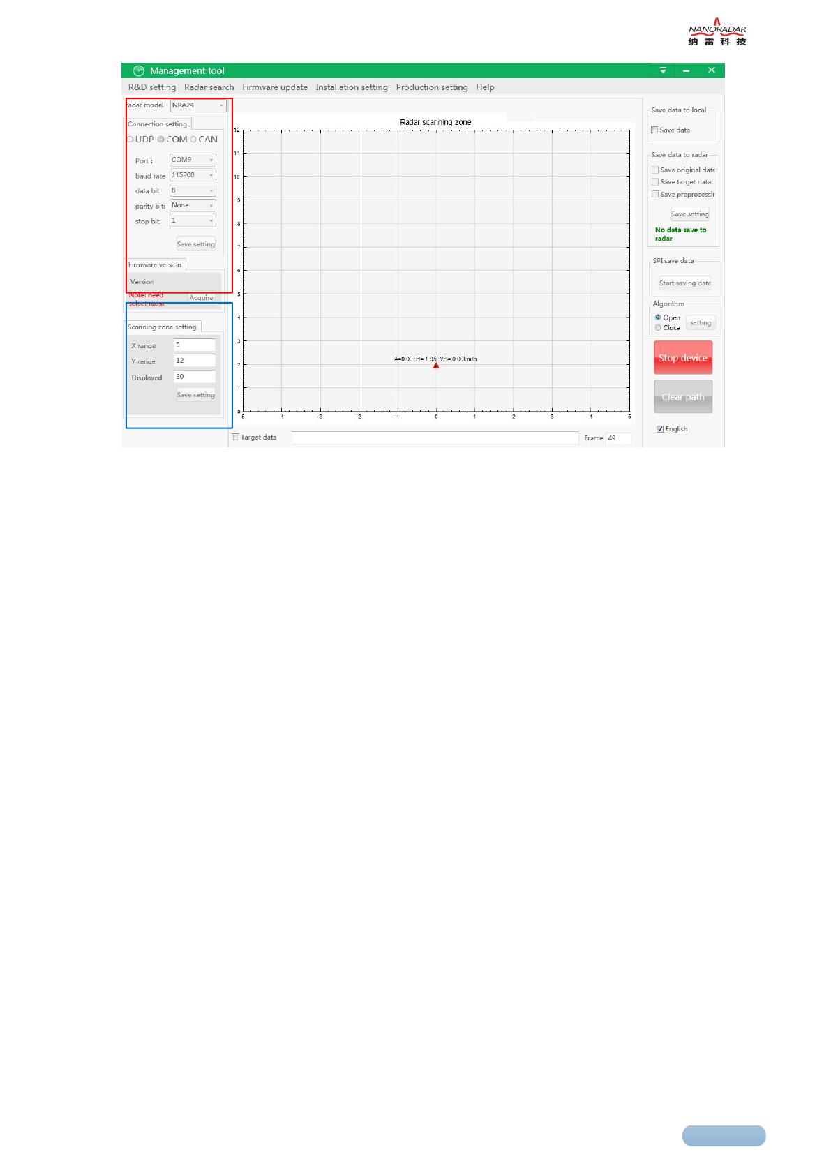
Figure 4 Radar PC test interface
4) Start to test. NRA24 radar antenna faces directly to the moving target, or there is relatively
small movement between the sensor and the target. You can see the target indicator of the red
triangle in the UI interface, and the target distance R. In Figure 4, the radial distance of the
target from the radar is 1.95meters (NRA24 could detect the target within 50 meters to ground).
If no red triangle is indicated, it states that there is no target within the detectable distance and
field of view. The following table shows the relationship between the sensor indicator light and
the corresponding indication status:
5 Serial-port data parsing
NRA24 radar sensor utilizes a UART-TTL interface with a default transmission rate of 115200
baud, 8 bit data bit, 1 stop bit, no parity bit, no flow control. Starting with a start sequence and
terminating with a termination sequence for each data message. At each data cycle of NRA24
(20ms), the message for NRA24 system status and target output status would be output. If the
field of detected target numbers in message of the detected target output status is 1, the target
output status message is followed by the target output information message which contains the
height parameter of the target.
PC or the peripheral device configures the NRA24 with the same message format, and the
corresponding message ID is 0x200.
A complete data message of UART-TTL communication is 14 bytes. Each byte of data is
unsigned8bit. The data range is 0 ~ 255 (0 ~ 0xFF). And the format is shown in the following
table. Each data message contains a message ID to distinguish between different types of
messages.
5
Table 3 Format of data message
Byte \ Bit
7
6
5
4
3
2
1
0
0
Start Sequence (2 x Uint8)
1
2
Message ID (2 x Uint8)
3
4
Data Payload (7 x Uint8 )
5
6
7
8
9
10
11
Check Sum (1 x Uint8 )
12
End Sequence (2 x Uint8)
13
The start Sequence is a constant value 0xAAAA, and the Message ID is defined as follows. The
Data Payload is defined according to the Message ID (see the next section). The End Sequence
is set to 0x5555.
Note:
The 11th byte is the check sum, which is the lower eight bits of the sum of the first seven data
payloads, that is the sum of bytes 4,5,6,7,8,9,10 of the lower eight.
Table 4 Definition of Message ID
Num
Message ID
Message Name
Comment
1
0x200
Sensor Configuration
NRA24configuration
2
0x400
Sensor Back
NRA24 back
3
0x60A
Sensor Status
NRA24 status
4
0x70B
Target Status
Target output status
5
0x70C
Target Info
Target output information
Note
The Message ID is represented by 2 bytes, Byte2 is the low byte, and Byte3 is the high byte.
For example, the output of the NRA24 message is 0xAA 0xAA | 0x0A 0x06 | Data Payload |
0x55 0x55, which indicates that the message ID is 0x60A (NRA24 system status) and Data
Payload is the NRA24 system status.
5.1 NRA24 configuration (Sensor Configuration)
NRA 24 configuration message is shown in the following table. The start sequence (0xAAAA)
and the termination sequence (0x5555) have been omitted from the table.
6
Table 5 NRA24 configuration message format
Message ID
0x200
Signal Name
Bit
Resolution
Interval
Type
Comment
DataType
0..6
1
0…127
u7
1: Sensor ID
2: Sensor Version
3: start/stop the target
information output
4:filter the range
7e:for internal test
7f:save parameter
R/W
7
1
0…1
u1
0:Read parameter;
1:write parameter
Parameter
8..31
1
-
u24
According to the
definition of DataType
Reserved
32..55
1
-
-
-
Check Sum
56..63
1
0…127
u8
The sum of lower eight
bits of first seven bytes
Note:
Currently, NRA24 only supports reading version information. Other functions are not yet
available. If R / W are 0, reading the parameters and the Parameter content is meaningless. If
the R / W are 1, that is, writing parameters, Parameter is defined according to DataType.
5.2 NRA24 back (Sensor Back)
After the PC or other MCU sends the configuration signal to NRA24, NRA24 will return the
execution result. The format is shown in the following table. The start sequence (0xAAAA) and
the termination sequence (0x5555) have been omitted from the table.
Table 6 NRA24 back message format
Message ID
0x400
Signal Name
Bit
Resolution
Interval
Type
Comment
DataType
0..6
1
0…127
u7
1: Sensor ID
2: Sensor Version
3:start/stop,target information output
4: range filtering
7e:for internal test
7f:Save parameters
esult
7
1
0…1
u1
0:fail to configure;
1:succeed to configure
Parameter
8..31
1
-
u24
Defined according to the DataType
Reserved
32..55
1
-
-
-
Check Sum
56..63
1
0…127
u8
The sum of lower eight bits of first
seven bytes
7
Note:
At present, NRA24 will only return version information; other functions are not yet available.
DataType indicates the configuration item, result indicates the configuration result, and
Parameter is the value of the configured DataType.
5.2.1 Sensor Version
After the PC or other MCU sends the read version information of sensor to NRA24, the NRA24
will return the execution result. When the version information is returned, the corresponding
Parameter field format is as follows:
Table 7 Sensor Version back format
Message ID
0x400
Signal Name
Bit
Resolution
Interval
Type
Comment
DataType
0..6
1
2
u7
1: Sensor ID;2: Sensor Version
3:start/stop
target information output
4: range filtering
7e:for internal test
7f:Save parameters
Result
7
1
0…1
u1
0:fail to read
1:succeed to read
Parameter
8..15
1
0…255
u8
Master Version
16..23
1
0…255
u8
Second Version
23..31
1
0…255
u8
Step Version
Reserved
32..55
1
-
-
-
Check Sum
56..63
1
0…255
u8
The sum of lower eight bits of first
seven bytes
5.3 NRA24 system status (Sensor Status)
The NRA24 system status message format is shown in the following table. The start sequence
(0xAAAA) and the termination sequence (0x5555) have been omitted from the table, where the
value of RollCount is fixed to 0.
Table 8 NRA24 system status message format
Message ID
0x60A
Signal Name
Bit
Resolution
Interval
Type
Comment
ACTL_Mode
0..6
1
0…127
u7
NRA24 is fixed to 1
RollCount
8..9
1
0…3
u2
The cycle count is 0-1-2-3and
it change one time per cycle
Rsvd1
10..11
1
-
u2
-
CfgStatus
12..15
1
-
u4
NRA24is fixed to 1
Rsvd2
15..55
1
-
-
-
Check Sum
56..63
1
0…255
u8
The sum of lower eight bits of
first seven bytes
8
5.4 Targets output status (Target Status)
The data message format for NRA24 system target output status is shown as in the table below.
The start sequence (0xAAAA) and termination sequence (0x5555) has been omitted for the
table, where the value of RollCount is continuously cycled between 0-1-2-3-0-1-2-3 ••••••.
When the PC or an external MCU cannot process the output data of the NRA24 sensor in time,
it will cause the received RollCount value to be discontinuous. At this time a faster removal
methods should be found to solve this problem.
Table 9 NRA24 Targets output status message format
Message ID
0x70B
Signal Name
Bit
Resolution
Interval
Type
Comment
NoOfTarget
0..7
1
0…255
u8
The numbers of detected targets
RollCount
8..9
1
0…3
u2
The cycle count is 0-1-2-3and
it change one time per cycle
Rsvd1
10..55
1
-
-
-
Check Sum
56..63
1
0…255
u8
The sum of lower eight bits of
first seven bytes
5.5 Target output information (Target Info)
The target output message format of NRA24 is shown in the following table. The start sequence
(0xAAAA) and the termination sequence (0x5555) have been omitted from the table. When the
radar sensor works normally and detects the target, it outputs the NRA24 system status message,
and then outputs the target output status message, and finally outputs the target output
information message.
Table 10 NRA24 target output information format
Message ID
0x70C
Signal Name
Bit
Resolution
Interval
Type
Comment
Index
0..7
1
0…255
u8
Target ID
Rcs
8..15
-
0…255
u8
The section of radar
reflection
RangeH
16..23
0.01m
0…255
u8
Target distance high 8 bit
RangeL
24..31
0.01m
0…255
u8
Target distance low 8 bit
Rsvd1
32..39
-
-
u8
-
VrelH
40..42
0.05m/s
0..7
u3
-
Rsvd1
43..45
1
1
u3
-
RollCount
46..47
1
-
u2
NRA24 is fixed to 0
VrelL
48..55
0.05m/s
0..255
u8
-
Check Sum
56..63
1dB
0..255
u8
The sum of lower eight bits
of first seven bytes
9
Note:
The value of each field in the table is not the true value of the target information. The true value
of the target information needs to be calculated through the following relations:
- Index = IndexValue // Target ID = 1. According to Track information, NRA24
outputs only one target.
- Rcs = RcsValue*0.5 – 50 // Factory test retention value, do not do output
- Range = (RangeHValue*256 + RangeLValue)*0.01 // The original data unit of the
radar output is cm, and the unit of target distance after conversion is meters
- RollCount = RollCountValue // counter
- Check sum = Check Sum // check sum Verify whether there is an error in the data
transmission
The target reflection Radar-Cross Section (RCS), the target range (Range)can be obtained by
these calculations, to accurately detect the targets.
10
6 Data parsing examples
Take Message ID as the target output information (Target Info) as an example, there is a frame
of the Target Info data message as follows:
Target Info Data:
0xAA 0xAA 0x0C 0x07 0x01 0xC8 0x07 0xD0 0x00 0x02 0xEE 0x90 0x55 0x55
Description:
Start Sequence Message ID Data Payload End Sequence
Interpretation
Start Sequence = 0xAAAA
Message ID = 0x0C + 0x07*0x100 = 0x70C
Data Payload = 0x01 0xC8 0x07 0xD0 0x00 0x02 0xEE 0x90
End Sequence = 0x5555
Each field of Data Payload is parsed as following
Index = 1
Rcs = 0xC8*0.5 – 50 = 50
Range = (0x07*0x100 +0xD0)*0.01 = 20
Rsvd1 = 0
RollCount = (0x0 & 0xE0) >> 5 = 0
Check sum = 0x90 // The sum of lower eight bits of first
seven bytes: 0x90 = 0xFF&0x290;
//0x290=0x01+0xC8+0x07+0xD0 +0x00+0x02 +0xEE
Note:
The user needs to program to parse the sensor output data
(hexadecimal).
The data before being parsed is hexadecimal, and is decimal after
being parsed. 0x2AF5 hexadecimal is converted to decimal:
10997 = 5 * 16 ^ 0 + F * 16 ^ 1 + A * 16 ^ 2 + 2 * 16 ^ 3
11
7 Electrostatic protection
7.1 Electrostatic protection measures
We need take the full electrostatic protection in the radar transport and storage. When handling
discrete modules that are not integrated, it is important to note that when the module is removed
from the sealed antistatic package, it is time to start with electrostatic protection. Never touch or
grab the radar antenna surface and connector pins, but the corner part.
Recommendation: When handling all radar sensors, please try to wear anti-static gloves.
Wrong methods
Use metal foil or some metal parts to wrap the antenna;
Measure the pin directly with a multimeter, causing damage.
Use any type of paint or varnish to spray antenna structure;
wrap antenna with CFK sheet (conductive);
The plastic material is in direct contact with the corroded antenna structure (which has a
higher dielectric constant for the resonant frequency of the patch).
7.2 Identification of electrostatic damages
In general, the following conditions indicate that the module has been subjected to electrostatic
damage:
Radar continuously outputs non-regular targets when there is no target in radar coverage;
When the DC value of the power supply voltage and current is within the normal range, the
output signal cannot be obtained.
8 Frequently asked questions (FAQ)
(1) Q: What about the angular accuracy of NRA24?
A: NRA24 is a 24GHz mmw radar altimeter with 1T1R antenna, which is developed by
Nanoradar. It cannot measure the target angle. For the radar with more than two receiving
antennas, it has the ability to measure the angle. Besides, the more antennas it has, the higher
accuracy of angle resolution it could realize.
(2) Q: What is the height accuracy of NRA24 at a height of 0.5 m?
12
A: TNRA24 adopts one transmitting and one receiving antenna, and the separation design of
antennas makes the radar have a high isolation in transmit / receive link, to improve the
dynamic range of radar target detection. At the same time, NRA24 utilizes the advanced
integrated planar microstrip array antenna, which contains 40 vertical polarization radiation
units for transmitting and receiving antennas. Therefore, it could achieve height accuracy during
the effective measurement range of 0.1-50m.
(3) Q: In the height measurement, when there is vegetation and ground, which will it be
subjected to? When there is water on the ground, which will it be subjected to, the ground
surface or water surface?
A: NRA24 is millimeter-wave radar with high range accuracy developed by Nanoradar. In
practical application, if the height is less than 3m, there would be great air flow below the plane,
and the vegetation is likely to be blown away, so the reference point is the ground or water
surface. If the airplane reaches over 5m, the airflow would not affect the vegetation below. And
in case that the vegetation density is large, then the reference point should be vegetation.
9 References
[1] White paper on NRA24 millimeter wave radar
[2] User manual for the general management system of Nanoradar mmw radar
Hunan Nanoradar Science and Technology Co., Ltd.
Tel.+86-731-88939916
No.27 Wenxuan Road, Hi-tech District Changsha
E-Mailsales@nanoradar.cn
B7 Lugu Compark
URLwww.nanoradar.cn
FCC Caution
This device complies with part 15 of the FCC Rules. Operation is subject to the
following two conditions: (1) This device may not cause harmful interference, and (2)
this device must accept any interference received, including interference that may
cause undesired operation.
Any Changes or modifications not expressly approved by the party responsible for
compliance could void the user's authority to operate the equipment.
Note: This equipment has been tested and found to comply with the limits for a Class
B digital device, pursuant to part 15 of the FCC Rules. These limits are designed to
provide reasonable protection against harmful interference in a residential installation.
This equipment generates uses and can radiate radio frequency energy and, if not
installed and used in accordance with the instructions, may cause harmful interference
to radio communications. However, there is no guarantee that interference will not
occur in a particular installation. If this equipment does cause harmful interference to
radio or television reception, which can be determined by turning the equipment off
and on, the user is encouraged to try to correct the interference by one or more of the
following measures:
-Reorient or relocate the receiving antenna.
-Increase the separation between the equipment and receiver.
-Connect the equipment into an outlet on a circuit different from that to which the
receiver is connected.
-Consult the dealer or an experienced radio/TV technician for help.
  • Page 1 1
  • Page 2 2
  • Page 3 3
  • Page 4 4
  • Page 5 5
  • Page 6 6
  • Page 7 7
  • Page 8 8
  • Page 9 9
  • Page 10 10
  • Page 11 11
  • Page 12 12
  • Page 13 13
  • Page 14 14
  • Page 15 15
  • Page 16 16

nanoradar NRA24 User manual

Type
User manual

The nanoradar NRA24 is a compact and lightweight K-band radar altimeter with a range of capabilities that make it ideal for use in various applications. With its 2cm measuring accuracy, small size, high sensitivity, and stable performance, the NRA24 is suitable for use in unmanned aircraft systems (UAS), helicopters, small airships, and other fields that require precise altitude measurement. Thanks to its 24GHz-ISM frequency band, it ensures reliable operation while complying with industry standards. The NRA24's compact design (130mm x 70mm x 14.

Ask a question and I''ll find the answer in the document

Finding information in a document is now easier with AI