Page is loading ...

Installation and Operation Manual
August 2023 88-A5AC4001-1A-EN
SAFETY WARNING
Only qualified personnel should install and service the equipment. The installation, starting up, and servicing of heating, ventilating,
and air-conditioning equipment can be hazardous and requires specific knowledge and training. Improperly installed, adjusted or
altered equipment by an unqualified person could result in death or serious injury. When working on the equipment, observe all pre-
cautions in the literature and on the tags, stickers, and labels that are attached to the equipment.
Models
A5AC4018A
A5AC4024A
A5AC4030A
A5AC4036A
A5AC4042A
A5AC4048A
A5AC4060A
Note: “Graphics in this document are for representation only.
Actual model may differ in appearance.”
Condensing Units
ALL phases of this installation must comply with NATIONAL, STATE AND LOCAL CODES
IMPORTANT – This Document is customer property and is to remain with this unit. Please return to service informa-
tion pack upon completion of work.
These instructions do not cover all variations in systems or provide for every possible contingency to be met in connection with
the installation. Should further information be desired or should particular problems arise which are not covered sufficiently for the
purchaser’s purposes, the matter should be referred to your installing dealer or local distributor.
Note: The manufacturer recommends installing only approved matched indoor and outdoor systems. All of the manufacture’s split
systems are AHRI rated only with TXV/EEV indoor systems. Some of the benefits of installing approved matched indoor and out-
door split systems are maximum efficiency, optimum performance and the best overall system reliability.

Section 1. Safety
WARNING
!
HAZARDOUS VOLTAGE!
Failure to follow this Warning could result in property
damage, severe personal injury, or death.
Disconnect all electric power, including remote
disconnects before servicing. Follow proper lockout/
tagout procedures to ensure the power cannot be
inadvertently energized.
WARNING
!
REFRIGERANT OIL!
Any attempt to repair a central air conditioning product
may result in property damage, severe personal injury,
or death.
Use only R-454B approved service equipment. All
R-454B systems with variable speed compressors use
variable speed compressor oil that readily absorbs
moisture from the atmosphere. To limit this
‘hygroscopic’ action, the system should remain sealed
whenever possible. If a system has been open to the
atmosphere for more than 4 hours, the compressor oil
must be replaced. Never break a vaccum with air and
always change the driers when opening the system for
component replacement.
HOT SURFACE!
May cause minor to severe burning. Failure to follow
this Caution could result in property damage or per-
sonal injury. Do not touch top of compressor.
CAUTION
!
CONTAINS REFRIGERANT!
Failure to follow proper procedures can result in
personal illness or injury or severe equipment
damage.
System contains oil and refrigerant under high
pressure. Recover refrigerant to relieve pressure
before opening system.
CAUTION
!
GROUNDING REQUIRED!
Failure to inspect or use proper service tools may
result in equipment damage or personal injury.
Reconnect all grounding devices. All parts of this
product that are capable of conducting electrical
current are grounded. If grounding wires, screws,
straps, clips, nuts, or washers used to complete a
path to ground are removed for service, they must be
returned to their original position and properly
fastened.
CAUTION
!
WARNING
!
SERVICE VALVES!
Failure to follow this warning will result in abrupt re-
lease of system charge and may result in personal in-
jury and/or property damage. Extreme caution should
be exercised when opening the Suction and Liquid
Line Service Valve. Turn valve stem counterclockwise
only until the stem contacts the rolled edge. No torque
is required.
WARNING
!
WARNING
!
BRAZING REQUIRED - IF USING MECHANICAL
CONNECTIONS, ENSURE LEAK TEST IS
NEGATIVE!
Failure to inspect lines or use proper service tools
may result in equipment damage or personal injury.
If using existing refrigerant lines make certain that all
joints are brazed, not soldered.
HIGH LEAKAGE CURRENT!
Failure to follow this Warning could result in property
damage, severe personal injury, or death.
Earth connection essential before connecting
electrical supply.
NOTE: R454B refrigerant is a blend and should only
be added to the system in liquid form.
Important: If using other than copper pipe, follow
manufacturer’s installation instructions. Joints must
be brazed or other UL/IMC/URMC approved joint that
meets pressure requirements.
WARNING
!
RISK OF FIRE!
Flammable refrigerant used. To be repaired only by
trained service personnel. Do not puncture refrigerant
tubing.
Dispose of properly in accordance with federal or local
regulations. Flammable refrigerant used.
VENTILATION
Ensure that the area is in the open or that it is ad-
equately ventilated before breaking into the system or
conducting any hot work.
WARNING
!
Mode Model Operating Range
Cooling 1.5 – 5 Ton 55°F – 120°F
Heating 1.5 – 5 Ton 0°F – 66°F
88-A5AC4001-1A-EN
2

88-A5AC4001-1A-EN 3
Table of Contents
Section 1. Safety ............................................................................................................................ ..............................2
Section 2. Unit Location Considerations .................................................................................... ..............................4
Section 3. Unit Preparation........................................................................................................... ..............................5
Section 4. Setting the Unit ............................................................................................................ ..............................5
Section 5. Refrigerant Line Considerations ................................................................................ ..............................5
Section 6. Refrigerant Line Routing ............................................................................................ ..............................6
Section 7. Refrigerant Line Brazing ............................................................................................. ..............................8
Section 8. Refrigerant Line Leak Check ...................................................................................... ..............................9
Section 9. Evacuation and Servicing ........................................................................................... ..............................9
Section 10. Service Valves ........................................................................................................... ............................10
Section 11. Electrical - Low Voltage ............................................................................................ ............................11
Section 12. Electrical - High Voltage ........................................................................................... ............................13
Section 13. Start Up....................................................................................................................... ............................13
Section 14. System Charge Adjustment (Systems can be rated with TXV, EEV or Piston) .. ............................14
Section 15. Checkout Procedures ............................................................................................... ............................18
Section 16. Refrigerant Circuits (Reference only) ...................................................................... ............................19
Section 17. Wiring Diagrams ........................................................................................................ ............................21
Section 18. Pressure Curves ........................................................................................................ ............................25

4 88-A5AC4001-1A-EN
D
W
H
Section 2. Unit Location Considerations
2.1 Unit Dimensions and Weight
2.2 Refrigerant Piping Limits
Table 2.1
When mounting the outdoor unit on a roof, be sure the roof will support the unit’s weight.
Properly selected isolation is recommended to alleviate sound or vibration transmission to the building structure.
1. The maximum TOTAL length of refrigerant lines from outdoor to indoor unit should NOT exceed 150 feet*
(including lift).
2 . The maximum vertical change should not exceed 50 feet*.
3 . Standard and alternate line sizes and service valve connection sizes are shown in Table 5.1.
* See Table 5.1 for exceptions for certain tonnages.
Note: For other line lengths, Refer to Refrigerant Piping Application Guide, SS-APG006F-EN, or Refrigerant
Piping Software Program.
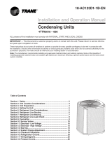
Min. 12” to
Shrubbery
Avoid Install
Near Bedrooms
Min 5’ Unrestricted
Access Panel
Min 3’
Unrestricted
2.3 Suggested Locations for Best Reliability
Ensure the top discharge area is unrestricted for at least
five (5) feet above the unit.
Three (3) feet clearance must be provided in front of the
control box (access panels) and any other side requiring
service.
It is not recommended to install in a location where noise
may distract the building occupants. Some examples
of these types of locations are sleeping quarters and by
windows of a living area. Please discuss location with the
building owner prior to installation.
Avoid locations such as near windows where condensation
and freezing defrost vapor can annoy a customer.
Position the outdoor unit a minimum of 12” from any wall or
surrounding shrubbery to ensure adequate airflow.
Outdoor unit location must be far enough away from any
structure to prevent excess roof runoff water or icicles from
falling directly on the unit.
Unit Dimensions and Weight
Models H x D x W (in) Weight* (lb)
A5AC4018A 36.6 x 29.8 x 29.8 184
A5AC4024A 161
A5AC4030A 36.6 x 29.8 x 29.8 184
A5AC4036A 32.6 x 29.8 x 29.8 161
A5AC4042A 36.6 x 34.3 x 34.3 212
A5AC4048A 44.3 x 34.3 x 34.3 252
A5AC4060A 44.3 x 34.3 x 34.3 252
* Weight values are estimated.
Standard
Line Set
60’ Max
Line Length
60’
Max
Vertical
Change
60’
Max
Vertical
Change
32.6 x 29.8 x 29.8

88-A5AC4001-1A-EN 5
2.4 Cold Climate Considerations
NOTE: It is recommended that these precautions be taken for units being installed in areas where snow accumu-
lation and prolonged below freezing temperatures occur.
• Units should be elevated 3-12 inches above the pad or roof top, depending on local weather. This additional
height will allow drainage of snow and ice melted during defrost cycle prior to its refreezing. Ensure that drain
holes in unit base pan are not obstructed preventing draining of defrost water.
• If possible, avoid locations that are likely to accumulate snow drifts. If not possible, a snow drift barrier should
be installed around the unit to prevent a build-up of snow on the sides of the unit.
Section 3. Unit Preparation
3.1 Prepare The Unit For Installation
STEP 1 - Check for damage and report promptly to the carrier any damage found to the unit.
Section 4. Setting the Unit
4.1 Pad Installation
When installing the unit on a support pad, such as a concrete slab, consider the following:
• The pad should be at least 1” larger than the unit on all sides.
• The pad must be separate from any structure.
• The pad must be level.
• The pad should be high enough above grade to allow for drainage.
• The pad location must comply with National, State, and Local codes.
For other applications refer to application guide.
Section 5. Refrigerant Line Considerations
5.1 Refrigerant Line and Service Valve Connection Sizes
Table 5.1
Note: For other line lengths, Refer to Refrigerant Piping Application Guide, SS-APG006F-EN, or Refrigerant
Piping Software Program.
RATED
LINE SIZES
Line Sizes Service Valve Connection Sizes Max Line & Lift Lengths
Vapor
Line
Liquid
Line
Vapor Line
Connection
Liquid Line
Connection
TOTAL Max
Line Length (ft.) Max Lift (ft.)
A5AC4018A 3/4 5/16 3/4 5/16 150 50
A5AC4024A 3/4 5/16 3/4 5/16 150 50
A5AC4030A 3/4 5/16 3/4 5/16 150 50
A5AC4036A 3/4 5/16 3/4 5/16 150 50
A5AC4042A 7/8 5/16 7/8 5/16 150 50
A5AC4048A 7/8 5/16 7/8 5/16 150 50
A5AC4060A 7/8 5/16 7/8 5/16 150 50
5.2 Factory Charge
The outdoor condensing units are factory charged with the system charge required for the outdoor condensing
unit, ten (10) feet of tested connecting line, and the smallest rated indoor evaporative coil match. Always verify
proper system charge via subcooling (TXV/EEV) or superheat (fixed orifice) per the unit nameplate.

6 88-A5AC4001-1A-EN
Line Length
5.3 Required Refrigerant Line Length
Determine required line length and lift. You will
need this later in STEP 2 of Section 14.
Total Line Length = __________ Ft.
Total Vertical Change (lift) = __________ Ft.
5.4 Refrigerant Line Insulation
Important: The Vapor Line must always be
insulated. DO NOT allow the Liquid Line and
Vapor Line to come in direct (metal to metal)
contact.
Vapor Line
Liquid Line
Insulation
5.5 Reuse Existing Refrigerant Lines
For retrofit applications, where the existing indoor evaporator coil and/or refrigerant lines will be used, the following
precautions should be taken:
• Ensure that the indoor evaporator coil and refrigerant lines are the correct size.
• Ensure that the refrigerant lines are free of leaks, acid, and oil.
Section 6. Refrigerant Line Routing
6.1 Precautions
Important: Take precautions to prevent noise
within the building structure due to vibration
transmission from the refrigerant lines.
For Example:
• When the refrigerant lines have to be fastened to floor joists or other framing in a structure, use isolation type
hangers.
• Isolation hangers should also be used when refrigerant lines are run in stud spaces or enclosed ceilings.
• Where the refrigerant lines run through a wall or sill, they should be insulated and isolated.
• Isolate the lines from all ductwork.
• Minimize the number of 90º turns.
Comply with National, State, and Local Codes when
isolating line sets from joists, rafters, walls, or other
structural elements.
CAUTION
!
If using existing refrigerant lines make certain that all joints are brazed, not soldered.

88-A5AC4001-1A-EN 7
Isolation From Joist/Rafter
Side View
8 Feet Maximum
Secure Vapor line from joists using isolators every 8 ft. Secure
Liquid Line directly to Vapor line using tape, wire, or other appro-
priate method every 8 ft.
Joist/Rafter
Isolator
Line Set
8 Feet Maximum
Isolation In Wall Spaces
Side View
Wall
Isolator
Line Set
8 Feet Maximum
Secure Vapor Line using isolators every 8 ft. Secure Liquid Line
directly to Vapor Line using tape, wire, or other appropriate
method every 8 ft.
8 Feet Maximum
Isolation Through Wall DO NOT hang line sets from ductwork
Sealant
Insulation
Vapor Line
Wall
Ductwork
Isolator
Line Set

8 88-A5AC4001-1A-EN
Section 7. Refrigerant Line Brazing
7.1 Braze The Refrigerant Lines
STEP 1 - Remove caps or plugs. Use a deburing tool to debur the pipe ends. Clean both internal and external
surfaces of the tubing using an emery cloth.
STEP 2 - Remove the pressure tap cap and valve cores from both service valves.
STEP 3 - Purge the refrigerant lines and indoor coil with dry nitrogen.
STEP 4 - Wrap a wet rag around the valve body to avoid heat damage and continue the dry nitrogen purge.
Braze the refrigerant lines to the service valves.
Continue the dry nitrogen purge. Do not remove the wet rag until all brazing is completed.
Important: Remove the wet rag before stopping the dry nitrogen purge.
Note: Install drier in Liquid Line.
NNOTE:OTE: Precautions should be taken to avoid heat damage to basepan during brazing. It is recommended to Precautions should be taken to avoid heat damage to basepan during brazing. It is recommended to
keep the flame directly off of the basepan.keep the flame directly off of the basepan.
STEP 5 - Replace the pressure tap valve cores after the service valves have cooled.
3-4” from valve
STEP 1 STEP 2 STEP 3
STEP 4 STEP 5

9
Section 8. Refrigerant Line Leak Check
8.1 Check For Leaks
88-A5AC4001-1A-EN
STEP 1 - Pressurize the refrigerant lines and
evaporator coil to 600 PSIG using dry nitrogen. 600 PSIG
STEP 2 - Check for leaks by using a soapy
solution or bubbles at each brazed location.
Note: Remove nitrogen pressure and repair any
leaks before continuing.
After completion of field piping for split systems, the field pipework shall be pressure tested with nitrogen and then
vacuum tested prior to refrigerant charging, according to the following requirements:
1. The minimum leak test pressure of the lineset and indoor coil shall be the high side design pressure, unless the
high side of the system, cannot be isolated from the low side of the system in which case the entire system
shall be pressure tested to the low side design pressure.
2. The test pressure after removal of pressure source shall be maintained for at least 1 hour with no decrease of
pressure indicated by the test gauge, with test gauge resolution not exceeding 5% of the test pressure.
Important: Under no circumstances shall potential sources of ignition be used in the searching for or detection of
refrigerant leaks.
Important: The following leak detection methods are deemed acceptable for all refrigerant systems:
• Electronic leak detectors calibrated for R454B
• Bubble method
STEP 2 - Observe the micron gauge. Evacuation
is complete, if the micron gauge does not rise
above 500 microns in one (1) minute and 1500
microns in ten (10) minutes.
STEP 3 - Once evacuation is complete, blank off
the vacuum pump and micron gauge, and close
the valve on the manifold gauge set.
1 MIN.
Important: Do not open the service valves until
the refrigerant lines and indoor coil leak check
and evacuation are complete.
STEP 1 - Evacuate until the micron gauge reads
no higher than 350 microns, then close off the
valve to the vacuum pump.
0350
Microns
ON OFF
Section 9. Evacuation and Servicing
9.1 Evacuate the Refrigerant Lines and Indoor Coil

9.2 Servicing
Under no circumstances shall potential sources of ignotion be used in the searching for or detection of refrigerant
leaks.
The following leak detection methods are deemed acceptable for all refrigerant systems:
• Electronic leak detectors calibrated for R454B
• Bubble method
• Fluorscent method agents
If a leakage of refirgerant is found which requires brazing, all of the refrigerant shall be recovered from the system,
or isolated (by means of shut off valves) in a part of the system remote from the leak.
• If repairs must be made after system is charged, properly and safely remove or isolate refrigerant and purge
the section of the system needing repair with Nitrogen gas or oxygen free nitrogen prior to opening the circuit.
• The REFRIGERANT CHARGE shall be recovered into the correctly marked recovery cylinders.
• Ensure that the outlet for the vaccum pump is not close to any potential ignition sources and the ventilation is
available.
• Prior to recharging the system, it shall be pressure-tested with the appropriate purging gas. The system shall
be leak-tested on completion of charging but prior to commissioning. A follow up leak test shall be carried out
prior to leaving the site.
• Ensure that only appropriate refrigerant recovery cylinders are employed. Ensure that the correct number of
cylinders for holding the total system charge is available. Only use cylinders designated for the recovered
refrigerant and labelled for the refrigerant. Cylinders shall be complete with pressure-relief valve and
associated shut-off valves in good working order.
• A set of caliberated weighing scales shall be available and in good working order. Hoses shall be complete
with leak-free disconnect couplings and in good condition. Ensure any associated electrical components are
sealed.
• The recovered refrigerant shall be returned to the refrigerant supplier in the correct recovery cylinder. Do not
mix refrigerants.
• If compressors or compressor oils are to be removed, ensure that they have been evacuated to an
acceptable level to make certain that FLAMMABLE REFRIGERANT does not remain within the lubricant.
Section 10. Service Valves
10.1 Open the Gas Service Valve
Important: Leak check and evacuation must be completed before opening the service valves.
NOTE: Do not vent refrigerant gases into the atmosphere.
STEP 1 - Remove valve stem cap.
STEP 2 - Using an adjustable wrench, turn valve stem 1/4 turn counterclockwise to the fully open position.
STEP 3 - Replace the valve stem cap to prevent leaks. Tighten finger tight plus an additional 1/6 turn.
10.2 Open the Liquid Service Valve
Important: Leak check and evacuation must be completed before opening the service valves.
STEP 1 - Remove service valve cap.
STEP 2 - Fully insert 3/16” hex wrench into the stem and back out counterclockwise until valve stem just touches
the rolled edge (approximately five (5) turns.)
STEP 3 - Replace the valve cap to prevent leaks. Tighten finger tight plus an additional 1/6 turn.
Extreme caution should be exercised when opening the Liquid Line Service Valve. Turn counterclockwise until
the valve stem just touches the rolled edge. No torque is required. Failure to follow this warning will result in
abrupt release of system charge and may result in personal injury and /or property damage.
WARNING
!
10 88-A5AC4001-1A-EN

11 88-A5AC4001-1A-EN
CAP
1/4 TURN ONLY
COUNTERCLOCKWISE
FOR FULL OPEN
POSITION
VALVE STEM
GAS LINE CONNECTION
UNIT SIDE
OF VALVE
PRESSURE TAP PORT
Cap
Rolled Edge to
Captivate Stem
Hex Headed
Valve System
Service Port
3/16” Hex Wrench
Unit Side
of Service
Valve
Gas Service Valve Liquid Service Valve
• The approved ID/OD combination will provide sufficient safe ventilation in case of a leak.
• Refer Indoor Unit Installer’s Guide for correct specifications on indoor unit install.
• All systems require mitigation boards so on altitude adjustment factors required.
• MCB neds to be included in an A2L System.
Mitigation Board Guidelines
Section 11. Electrical - Low Voltage
11.1 Low Voltage Maximum Wire Length
Table 11.1 defines the maximum total length of
low voltage wiring from the outdoor unit, to the
indoor unit, and to the thermostat.
Table 11.1
24 VOLTS
WIRE SIZE MAX. WIRE LENGTH
18 AWG 150 Ft.
16 AWG 225 Ft.
14 AWG 300 Ft.

• Units with pigtails require wirenuts for connections. Cap all unused wires.
•
11.2 Low Voltage Hook-up Diagrams
With 5TEM 4, 5, C With 5TAM5, X
In AC systems for multiple stages of electric heat, jumper W1 and W2 together if comfort control has only one stage of heat.
•
TEM3/4 - Bypass air handler and connect Y from comfort control directly to OD unit
* TEM6 Onl
y
** TEM6 only - When using a BK enabled comfort control, cut BK jumper and bypass Y1 and Y2 at the air handle
r. Connect BK from comfort
control to BK of the air handle
r
•
TAM4 only - Wire as shown, no BK is available
•
TAM7 only - When using a BK enabled comfort control, cut BK jumper on the AFC and connect BK from comfort control to BK of the air handler
Thermostat Air Handler Outdoor
Unit
R
G
B
W1
W2
B
Y
R
G
B/C
Y
W1
W2
Blue
24 VAC HOT
FAN
24 VAC
Common
SOV
COOL/HEAT
1st STAGE
HEATING
2nd STAGE
EMERGENCY
HEAT Pink
White
O
Y1
Y2
*
BK
WH/BLK
BK
WH/BLK
Thermostat Air Handler Outdoor
Unit
R
G
B
W1
W2
B
R
G
B/C
Yl
W1
W2
Blue
24 VAC HOT
FAN
24 VAC
Common
SOV
COOL/HEAT
1st STAGE
HEATING
2nd STAGE
EMERGENCY
HEAT Pink
White
O
Yl
YOYO
BK
WH/BLK
BK
WH/BLK
**
With Furnace With Variable Speed Furnace
• Units with pigtails require wirenuts for connections. Cap all unused wires.
•
In AC systems for multiple stages of heat, jumper W1 and W2 together if comfort control has only one stage of heat.
* If equipped with second stage heat
** When using a BK enabled comfort control, cut BK jumper and bypass Y and YLo at the furnace. Connect BK from comfort control
to
BK of the furnace
Thermostat Furnace Furnace
Outdoor
Unit
R
G
B
W1
W2
B
Y
R
G
B/C
W1
W2
24 VAC HOT
FAN
24 VAC
Common
COOL
HEATING
YY1 YY
Y
LO
Thermostat Outdoor
Unit
R
G
B
W1
W2
B
R
G
B/C
Y1
W1
W2
24 VAC HOT
FAN
24 VAC
Common
COOL
HEATING
O
BK
BK **
**
12 88-A5AC4001-1A-EN

13 88-A5AC4001-1A-EN
LIVE ELECTRICAL COMPONENTS!
During installation, testing, servicing, and
troubleshooting of this product, it may be nec-
essary to work with live electrical components.
Failure to follow all electrical safety precau-
tions when exposed to live electrical compo-
nents could result in death or serious injury.
WARNING
!
12.2 High Voltage Disconnect Switch
12.3 High Voltage Ground
Ground the outdoor unit per national, state, and local code requirements.
Install a separate disconnect switch at the outdoor unit.
For high voltage connections, flexible electrical conduit is recommended whenever vibration transmission may
create a noise problem within the structure.
Section 13. Start Up
13.1 System Start Up
STEP 1 - Ensure Sections 7 through 12 have been completed.
STEP 2 - Set System Thermostat to OFF.
STEP 3 - Turn on disconnect(s) to apply power to the indoor and outdoor units.
STEP 4 - Wait one (1) hour before starting the unit if compressor crankcase heater accessory is used and the
Outdoor Ambient is below 70ºF.
STEP 5 - Set system thermostat to ON.
Section 12. Electrical - High Volta ge
12.1 High Volta ge Power Suppl y

14 88-A5AC4001-1A-EN
STEP 1 - Check the outdoor temperatures.
Subcooling (in cooling mode) is the only recom-
mended method of charging above 55º F ambi-
ent outdoor temperature.
Note: For Superheat (In Cooling Mode), refer to
the Superheat Charging Table
For best results the indoor temperature should
be kept between 70º F to 80º F.
Note: It is important to return in the spring or
summer to accurately charge the system in the
cooling mode when outdoor ambient tempera-
ture is above 55º F.
STEP 1 - Use the refrigerant line total length
and lift measurements from Section 5 and use
line length adders as shown in Section 5.2 if
required.
Total Line Length = __________ Ft.
Vertical Change (Lift) = __________ Ft.
Note: Use this method when matched with a
TXV or EEV indoor unit.
Section 14. System Charge Adjustment (Systems can be rated with TXV, EEV or Piston)
14.1 Temperature Measurements
14.2 Subcooling Charging in Cooling (Above 55º F Outdoor Temp.)
Indoor Temp
80º F
70º F
Outdoor Temp
55º F
120º F
LIFT
NOTE: For systems using a indoor piston metering device, refer to the Superheat charging method and chart.
For systems using a TXV or EEV indoor metering device, refer to Subcool charging method and charts.

15
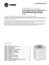
STEP 2 -
Determine the final subcooling value using
total Line Length and Lift measured in STEP 1 and
the charts below.
88-A5AC4001-1A-EN
8 9 10 11 12 13 14
170 172 175 178 181 184 187
184 187 190 194 197 200 203
200 203 206 210 213 217 220
217 220 223 227 230 234 238
234 238 241 245 249 252 256
252 256 260 264 268 272 276
272 276 280 284 288 292 297
292 297 301 305 309 314 318
314 318 323 327 332 336 341
336 341 346 351 355 360 365
360 365 370 375 380 385 390
385 390 396 406 412 417
412 417 422 428 433 439 445
439 445 450 456 462 468 474
468 474 480 486 492 498 504
R-454B REFRIGERANT CHARGING CHART
55
60
65
70
75
80
85
90
95
100
105
110
115
120
125
LIQUID
TEMP
(°F)
DESIGN SUBCOOLING (°F)
LIQUID GAGE PRESSURE (PSI)
401
018 & 030 Models
50
1°
40
30
25
Use Design Subcooling
15
1°
10
0
20 30 40 50 60 70 80 90 100 110 120130 140 150
Add 1°
REFRIGERANT LINE LIFT (FT)
SUBCOOL CHARGING CHART CORRECTIONS TABLE (FOR LINE LENGTH AND RISE)
TOTAL REFRIGERANT LINE LENGTH (FT) - [ includes lift ]
Add 2°
Add 1°
024, 036 & 042 Models
50
4°
40
30
25
Use Design Subcooling
15
1°
10
0
20 30 40 50 60 70 80 90 100 110 120130 140 150
Add 1°
Add 2°
REFRIGERANT LINE LIFT (FT)
SUBCOOL CHARGING CHART CORRECTIONS TABLE (FOR LINE LENGTH AND RISE)
TOTAL REFRIGERANT LINE LENGTH (FT) - [ includes lift ]
Add 1°
048 & 060 Models
50
1°
40
1°
30
25
Use Design Subcooling
15
10
0
1°
20 30 40 50 60 70 80 90 100110 120130 140 150
Add 4°
Add 2°
Add 1°
Add 1°
REFRIGERANT LINE LIFT (FT)
SUBCOOL CHARGING CHART CORRECTIONS TABLE (FOR LINE LENGTH AND RISE)
TOTAL REFRIGERANT LINE LENGTH (FT) - [ includes lift ]
Design Subcooling Value = __________º F
(from nameplate or Service Facts)
Final Subcooling Value = __________º F
Subcooling Correction = __________º F

16 88-A5AC4001-1A-EN
STEP 1 - Attain Proper Gage Pressure.
Using the Standard R-454B Subcool Charging Chart,
adjust refrigerant level to attain proper gage pressure.
Note: Use bubble point, per the included chart, for
calculating subcooling.
Add refrigerant in the Liquid Gage Pressure is lower than
the chart value.
1. Connect gauges to refrigerant bottle and unit are
illustrated.
2. Purge all hoses.
3. Place refrigerant bottle on a scale and then open
bottle.
4. Stop adding refrigerant when liquid line refrigerant
and Liquid Gage Pressure match the charging chart.
Note: Recover refrigerant if the Liquid Gage Pressure is
higher than the chart value.
Note: Ensure that contamination of different refrigerants
does not ___ when using charging equipment.
Cylinders sahll be kept in an appropriate position
according to the instructions. Ensure that the
REFRIGERATING SYSTEM is earther prior to charging
the system with refrigerant.
20 MIN.
STEP 2 - Stabilize the system.
1. Wait 20 minutes for the system condi-
tion to stabilize between adjustments.
Note: When the Liquid Line Temperature and
Gage Pressure approximately match the chart,
the system is properly charged.
2. Remove gages.
3. Replace service port caps to prevent
leaks. Tighten finger tight plus an ad-
ditional 1/6 turn.
STEP 3 - Record System Information for reference.
Record system pressures and temperatures after
charging is complete.
Outdoor model number = _________________
Measured Outdoor Ambient = __________ º F
Measured Indoor Ambient = __________ º F
Measured Liquid Line Temp = __________ º F
Measured Suction Line Temp = __________ º F
Liquid Gage Pressure = __________ PSI
Suction Gage Pressure = __________ PSI
STEP 4 - Complete the ‘Total System Charge’ charge rating label below and label located on the outside of the
unit with a permanent marker.
a. Charge added at Factory = ___________ lb/oz
b. Charge added at install = ___________ lb/oz
c. Total System Charge (a + b) = ___________ lb/oz
14.3 Charging the Unit

17 88-A5AC4001-1A-EN
Weigh-In Method can be used for the initial
installation, or anytime a system charge is being
replaced. Weigh-In Method can also be used
when power is not available to the equipment
site or operating conditions (indoor/outdoor
temperatures) are not in range to verify with the
subcooling charging method.
14.4 Weigh-In Method for Charging
Indoor Wet Bulb Temp (F)
Outdoor
Dry
Bulb
Temp.
(F)
50 51 52 53 54 55 56 57 58 59 60 61 62 63 64 65 66 67 68 69 70 71 72 73 74 75 76 77 78
55 7 9 10 11 12 14 15 17 18 20 21 23 24 26 27 29 30
60 5 7 8 9 10 12 13 15 16 18 19 21 22 24 25 27 28 30 31
65 4 6 8 10 11 13 14 16 17 18 19 21 22 24 25 27 28 27 31
70 5 7 8 10 11 13 14 16 17 18 19 21 22 24 25 27 28 30 31
75 5 6 7 9 10 12 14 16 18 19 21 22 24 26 28 29 31 32
80 4 6 7 9 10 11 12 14 16 18 19 21 23 25 26 28 29 31 33
85 4 6 7 9 10 13 14 16 18 20 21 23 24 26 28 29 30 31 32
90 4 6 8 10 11 13 14 16 18 20 22 24 25 27 28 30 31
95 4 6 8 10 13 14 16 18 20 22 23 25 26 28 29
100 6 8 10 12 13 16 18 20 21 23 25 27 29
105 4 6 7 9 11 13 15 18 20 22 24 26 28
110 4 7 9 11 13 16 18 21 23 26 28
115 6 9 12 14 16 19 21 24 26
Using a digital psychrometer, measure the return air wet-bulb temperature at the unit just before the coil. Also measure the outdoor dry-bulb tem-
perature. Use these temperatures to locate the target superheat on the charging table. Do not attempt to charge the system if these conditions fall
outside of this charging table.
ADD refrigerant to DECREASE total superheat. REMOVE refrigerant to INCREASE total superheat. Always allow 10 to 15 minutes of operature
after any refrigerant or air flow change prior to determining the final superheat.
Fixed Orifice Superheat Charging Table
Calculating Charge Using the Weigh-In Method
STEP 1 - Measure in feet the distance between the
outdoor unit and the indoor unit and record on Line 1.
Include the entire length of the line from the service
valve to the IDU.
STEP 2 - Enter the charge multiplier (0.4 oz/ft). Each
linear foot of interconnecting tubing requires the
addition of 0.4 oz of refrigerant.
STEP 3 - Multiply the total length of refrigerant tubing
(Line 1) times the value on Step 2. Record the result
on Line 3 of the Worksheet.
STEP 4 - This is the amount of refrigerant to weigh-in
prior to opening the service valves.
1. Line length (ft) ______________
2. Charge multiplier x ____ 0.4 ______
3. Step 1 x Step 2 = _____________
4. Refrigerant = _____________

18 88-A5AC4001-1A-EN
1. Leak check refrigerant lines. ........................................ [ ]
2. Properly insulate suction lines and fittings. ................... [ ]
3. Properly secure and isolate all refrigerant lines. ........... [ ]
4. Seal passages through masonry.
If mortar is used, prevent mortar from coming
into direct contact with copper tubing. .......................... [ ]
5. Verify that all electrical connections are tight. ............... [ ]
6. Observe outdoor fan during on cycle for clearance
and smooth operation. .................................................. [ ]
7. Be sure that indoor coil drain line drains freely. Pour water
into drain pan. ............................................................... [ ]
8. Be sure that supply registers and return grilles are open
and unobstructed. ......................................................... [ ]
Section 15. Checkout Procedures
15.1 Operational And Checkout Procedures
CHECKOUT PROCEDURE
After installation has been completed, it is recommended that the entire system be checked against the following list:
Final phases of this installation are the unit Operational and Checkout Procedures. To obtain proper performance, all units
must be operated and charge adjustments made.
Important: Perform a final unit inspection to be sure that factory tubing has not shifted during shipment. Adjust tubing if nec-
essary so tubes do not rub against each other when the unit runs. Also be sure that wiring connections are tight and properly
secured.
9. Be sure that a return air filter is installed. ..................... [ ]
10. Be sure that the correct airflow setting is used.
(Indoor blower motor) ................................................... [ ]
11. Operate complete system in each mode to
ensure safe operation. .................................................. [ ]
STEP 6 - Return to site for adjustment.
Important: Return in the spring or summer to accurately charge the system in the cooling mode with outdoor
ambient above 55º F.
STEP 5 - Complete the ‘Total System Charge’ charge rating label below and label located on the outside of the
unit with a permanent marker.
Note: Complete the ‘Total System Charge’ chart when fi nal charging is complete.
a. Charge added at Factory = ___________ lb/oz
b. Charge added at install = ___________ lb/oz
c. Total System Charge (a + b) = ___________ lb/oz

PRINTED FROM D157394P01
024 & 036 Models
PRINTED FROM D158514P01
018, 030 & 042 Models
Section 16. Refrigeration Circuits
88-A5AC4001-1A-EN 19

048 & 060 Models
Printed from D159175
20 88-A5AC4001-1A-EN
/