Page is loading ...

August
1988
FORM:
123
516
Effective
With
Serial
No.
JJ373747
MODEL
Ps-i
005
PS-2000
F~
LE
~
RETURL~\~
~
~
.
MODEL/STOCK
NO.
SERIAL/STYLE
NO.
DATE
PURCHASED
OWNERS
MANUAL
BAY
STATE
ABRASIVES
~ER
INDUSTRIAL
PRODUCTS
SUBDIVISION


TABLE
OF
CONTENTS
Section
No.
Page
No.
SECTION
1
-
SAFETY
RULES
FOR
OPERATION
OF
ARC
WELDING
POWER
SOURCE
1
-
1.
Introduction
1
1
-
2.
General
Precautions
1
1
-3.
ArcWelding
4
1
-
4.
Standards
Booklet
Index
6
SECTION
2
-
INTRODUCTION
2
-
1.
General
Information
And
Safety
7
2
-
2.
Receiving-Handling
7
2
-
3.
Description
7
SECTION
3
-
INSTALLATION
3-1.
Location
8
3
-
2.
Secondary
Connections
8
3
-
3.
Open-Circuit
Voltage
Connections
9
3
-
4.
Remote
Control
Connections
9
3-5.
Electricallnput
Connections
10
SECTION
4
-
OPERATOR
CONTROLS
4-1.
PilotLight
11
4
-
2.
Volt-Ampere
Curves
11
4-3.
DutyCycle
11
4
-
4.
115
Volts
AC
Duplex
Receptacle
11
4
-
5.
Overload
Protection
11
SECTION
5
-
SEQUENCE
OF
OPERATION
SECTION
6
-
MAINTENANCE
6-1.
FanMotor
12
6
-
2.
Internal
Cleaning
12
6-3.
Spark
Gaps
12
SECTION
7
-
TROUBLESHOOTING


SECTION
1
SAFETY
RULES
FOR
OPERATION
OF
ARC
WELDING
POWER
SOURCE
1-1.
INTRODUCTION
We
learn
by
experience.
Learning
safety
through
per
sonal
experience,
like
a
child
touching
a
hot
stove
is
harmful,
wasteful,
and
unwise.
Let
the
experience
of
others
teach
you.
Safe
practices
developed
from
experience
in
the
use
of
welding
and
cutting
are
described
in
this
manual.
Re
search,
development,
and
field
experience
have
evolved
reliable
equipment
and
safe
installation,
opera
tion,
and
servicing
practices.
Accidents
occur
when
equipment
is
improperly
used
or
maintained.
The
rea
son
for
the
safe
practices
may
not
always
be
given.
Some
are
based
on
common
sense,
others
may
require
technical
volumes
to
explain.
It
is
wiser
to
follow
the
rules.
Read
and
understand
these
safe
practices
before
at
tempting
to
install,
operate,
or
service
the
equipment.
Comply
with
these
procedures
as
applicable
to
the
par
ticular
equipment
used
and
their
instruction
manuals,
for
personal
safety
and
for
the
safety
of
others.
Failure
to
observe
these
safe
practices
may
cause
seri
ous
injury
or
death.
When
safety
becomes
a
habit,
the
equipment
can
be
used
with
confidence.
These
safe
practices
are
divided
into
two
Sections:
1-General
Precautions,
common
to
arc
welding
and
cut
ting;
and
2-Arc
Welding
(and
Cutting)
(only).
Reference
standards:
Published
Standards
on
safety
are
also
available
for
additional
and
more
complete
pro
cedures
than
those
given
in
this
manual.
They
are
listed
in
the
Standards
Index
in
this
manual.
ANSI
Z49.1
is
the
most
complete.
The
National
Electrical
Code,
Occupational
Safety
and
Health
Administration,
local
industrial
codes,
and
local
inspection
requirements
also
provide
a
basis
for
equip
ment
installation,
use,
and
service.
1-2.
GENERAL
PRECAUTIONS
Different
arc
welding
processes,
electrode
alloys,
and
fluxes
can
produce
different
fumes,
gases,
and
radiation
levels.
in
addItion
to
the
Information
In
this
manual,
be
sure
to
consult
flux
and
electrode
manufacturers
Material
Safety
Data
Sheets
(MSDS5)
for
specific
technIcal
data
and
precautIon
ary
measures
concerning
their
material.
A.
Burn
Prevention
Wear
protective
clothing-gauntlet
gloves
designed
for
use
in
welding,
hat,
and
high
safety-toe
shoes.
Button
shirt
collar
and
pocket
flaps,
and
wear
cuffless
trousers
to
avoid
entry
of
sparks
and
slag.
Wear
helmet
with
safety
goggles
and
glasses
with
side
shields
underneath,
appropriate
filler
lenses
or
plates
(frotected
by
clear
cover
glass).
This
is
a
MUST
for
welding
or
cutting,
(and
chipping)
to
protect
the
eyes
from
radiant
energy
and
flying
metal.
Replace
cover
glass
when
broken,
pitted,
or
spattered.
See
1
-3A2.
Avoid
oily
or
greasy
clothing.
A
spark
may
ignite
them.
Hot
metal
such
as
electrode
stubs
and
workpieces
should
never
be
handled
without
gloves.
Medical
first
aid
and
eye
treatment.
First
aid
facilities
and
a
qualified
first
aid
person
should
be
available
for
each
shift
unless
medical
facilities
are
close
by
for
im
mediate
treatment
of
flash
burns
of
the
eyes
and
skin
burns.
Ear
plugs
should
be
worn
when
working
on
overhead
or
in
a
confined
space.
A
hard
hat
should
be
worn
when
others
work
overhead.
Flammable
hair
preparations
should
not
be
used
by
per
sons
intending
to
weld
or
cut.
B.
Toxic
Fume
Prevention
Severe
discomfort,
illness
or
death
can
result
from
fumes,
vapors,
heat,
or
oxygen
enrichment
or
depletion
that
welding
(or
cutting)
may
produce.
Prevent
them
with
adequate
ventilation
as
described
in
ANSI
Stan
dard
Z49.1
listed
in
Standards
Index.
NEVER
veQ~late
with
oxygen.
Lead
-,cadmium-,
zinc-,
mercury
-,and
beryllium-bear
ing
and
similar
materials,
when
welded
(or
Cut)
may
pro
duce
harmful
concentrations
of
toxic
fumes.
Adequate
local
exhaust
ventilation
must
be
used,
or
each
person
in
the
area as
well
as
the
operator
must
wear
an
air-sup
plied
respirator.
For
beryllium,
both
must
be
used.
Metals
coated
with
or
containing
materials
that
emit
toxic
fumes
should
not
be
heated
unless
coating
is
re
moved
from
the
work
surface,
the
area
iswell
ventilated
and,
if
necessary,
while
wearing
an
air-supplied
respira
tor.
Work
in
a
confined
space
only
while
it
is
being
ventilated
and,
if
necessary,
while
wearing
an
air-supplied
respira
tor.
Gas
leaks
in
a
confined
space
should
be
avoided.
Leaked
gas
in
large
quantities
can
change
oxygen
con
centration
dangerously.
Do
not
bring
gas
cylinders
into
a
confined
space.
Leaving
confined
space,
shut
OFF
gas
supply
at
source
to
prevent
possible
accumulation
of
gases
in
the
space
if
downstream
valves
have
been
accidentally
opened
or
left
open.
Check
to
be
sure
that
the
space
is
safe
before
re-entering
it.
Vapors
from
chlorinated
solvents
can
be
decomposed
by
the
heat
of
the
arc
(or
flame)
to
form
PHOSGENE,
a
highly
toxic
gas,
and
other
lung
and
eye
irritating
prod
ucts.
The
ultraviolet
(radiant)
energy
of
the
arc
can
also
decompose
trichloroethylene
and
perchloroethylene
vapors
to
form
phosgene.
DO
NOT
WELD
or
cut
where
solvent
vapors
can
be
drawn
into
the
welding
or
cutting
123516
Page
1

atmosphere
or
where
the
radiant
energy
can
penetrate
to
atmospheres
containing
even
minute
amounts
of
trichloroethylefle
or
perchioroethylene.
C.
Fire
and
Explosion
Prevention
Causes
of
fire
and
explosion
are:
combustibles
reached
by
the
arc,
flame,
flying
sparks,
hot
slag
or
heated
mate
rial;
misuse
of
compressed
gases
and
cylinders;
and
short
circuits.
BE
AWARE
THAT
flying
sparks
or
falling
slag
can
pass
through
cracks,
along
pipes,
through
windows
or
doors,
and
through
wail
or
floor
openings,
out
of
sight
of
the
goggled
operator.
Sparks
and
slag
can
fly
35
feet.
To
prevent
fires
and
explosion:
Keep
equipment
clean
and
operable,
free
of
oil,
grease,
and
(in
electrical
parts)
of
metallic
particles
that
can
cause
short
circuits.
if
combustibles
are
in
area,
do
NOT
weld
or
cut.
Move
the
work
if
practicable,
to
an
area
free
of
combustibles.
Avoid
paint
spray
rooms,
dip
tanks,
storage
areas,
venti
lators.
If
the
work
cannot
be
moved,
move
combustibles
at
least
35
feet
away
out
of
reach
of
sparks
and
heat;
or
protect
against
ignition
with
suitable
and
snug-fitting,
fire-resistant
covers
or
shields.
Walls
touching
combustibles
on
opposite
sides
should
not
be
welded
on
(or
cut).
Walls,
ceilings,
and
floor
near
work
should
be
protected
by
heat-resistant
covers
or
shields.
Fire
watcher
must
be
standing
by
with
suitable
fire
extin
guishing
equipment
during
and
for
some
time
after
weld
ing
or
cutting
if:
a.
appreciable
combustibles
(including
building
construction)
are
within
35
feet
b.
appreciable
combustibles
are
further
than
35
feet
but
can
be
ignited
by
sparks
c.
openings
(concealed
orvisible)
in
floors
orwalis
within
35
feet
may
expose
combustibles
to
sparks
d.
combustibles
adjacent
to
walls,
ceilings,
roofs,
or
metal
partitions
can
be
ignited
by
radiant
or
conducted
heat.
Hot
work
permit
should
b&bbtained
before
operation
to
ensure
supervisors
approval
that
adequate
precautions
have
been
taken.
After
work
is
done,
check
that
area
is
free
of
sparks,
glowing
embers,
and
flames.
An
empty
container
that
held
combustibles,
or
that
can
produce
flammable
or
toxic
vapors
when
heated,
must
never
be
welded
on
or
cut,
unless
container
has
first
been
cleaned
as
described
in
AWS
Standard
A6.O,
listed
7
in
Standards
Index.
This
includes:
a
thorough
steam
or
caustic
cleaning
(or
a
solvent
or
water
washing,
depending
on
the
combusti
bles
solubility)
followed
by
purging
and
inerting
with
ni
trogen
or
carbon
dioxide,
and
using
protective
equip-
123516
Page
2
ment
as
recommended
in
A6.O.
Waterfilling
just
below
working
level
may
substitute
for
inerting.
A
container
with
unknown
contents
should
be
cleaned
(see
preceding
paragraph).
Do
NOT
depend
on
sense
of
smell
or
sight
to
determine
if
it
is
safe
to
weld
or
Cut.
Hollow
castings
or
containers
must
be
vented
before
welding
or
cutting.
They
can
explode.
Explosive
atmospheres.
Never
weld
or
cut
where
the
air
may
contain
flammable
dust,
gas,
or
liquid
vapors
(such
as
gasoline).
0.
Compressed
Gas
EquIpment
Standard
precautions.
Comply
with
precautions
in
this
manual,
and
those
detailed
in
CGA
Standard
P-i,
SAFE
HANDLING
OF
COMPRESSED
GASES
IN
CYLIN
DERS,
listed
11
in
Standards
Index.
1.
Pressure
Regulators
Regulator
relief
valve
is
designed
to
protect
only
the
regulator
from
overpressure;
itis
not
intended
to
protect
any
downstream
equipment.
Provide
such
protection
with
one
or
more
relief
devices.
Never
connect
a
regulator
to
a
cylinder
containing
gas
other
than
that
for
which
the
regulator
was
designed.
Remove
faulty
regulator
from
service
immediately
for
repair
(first
close
cylinder
valve).
The
following
symp
toms
indicate
a
faulty
regulator:
Leaks-if
gas
leaks
externally.
Excessive
Creep-if
delivery
pressure
continues
to
rise
with
downstream
valve
closed.
Faulty
Gauge-if
gauge
pointer
does
not
move
off
stop
pin
when
pressurized,
nor
returns
to
stop
pin
after
pres
sure
release.
Repair.
Do
NOT
attempt
to
repair.
Send
faulty
regula
tors
for
repair
to
manufacturers
designated
repair
cen
ter,
where
special
techniques
and
tools
are
used
by
trained
personnel.
2.
Cylinders
Cylinders
must
be
handled
carefully
to
prevent
leaks
and
damage
to
their
walls,
valves,
or
safety
devices:
Avoid
electrical
circuit
contact
with
cylinders
including
third
rails,
electrical
wires,
or
welding
circuits.
They
can
produce
short
circuit
arcs
that
may
lead
to
a
serious
ac
cident.
(See
1-3C.)
ICC
or
DOT
marking
must
be
on
each
cylinder.
It
is
an
assurance
of
safety
when
the
cylinder
is
properly
han
dled.
Identifying
gas
content.
Use
only
cylinders
with
name
of
gas
marked
on
them;
do
not
rely
on
color
to
identify
gas
content.
Notify
supplier
if
unmarked.
NEVER
DEFACE
or
alter
name,
number,
or
other
markings
on
a
cylinder.
It
is
illegal
and
hazardous.
Empties:
Keep
valves
closed,
replace
caps
securely;
mark
MT;
keep
them
separate
from
FULLS
and
return
promptly.
Prohibited
use.
Never
use
a
cylinder
or
its
contents
for
other
than
its
intended
use,
NEVER
as
a
support
or
roller.

Locate
or
secure
cylinders
so
they
cannot
be
knocked
over.
Passageways
and
work
areas.
Keep
cylinders
clear
of
areas
where
they
may
be
struck.
Transporting
cylinders.
With
a
crane,
use
a
secure
sup
port
such
as
a
platform
or
cradle.
Do
NOT
lift
cylinders
off
the
ground
by
their
vjlves
or
caps,
or
by
chains,
slings,
or
magnets.
Do
NOT
expose
cylinders
to
excessive
heat,
sparks.
slag,
and
flame,
etc.
that
may
cause
rupture.
Do
not
al
low
contents
to
exceed
130F.
Cool
with
water
spray
where
such
exposure
exists.
Protect
cylinders
particularly
valves
from
bumps,
falls,
falling
objects,
and
weather.
Replace
caps
securely
when
moving
cylinders.
Stuck
valve.
Do
NOT
use
a
hammer
or
wrench
to
open
a
cylinder
valve
that
can
not
be
opened
by
hand.
Notify
your
supplier.
Mixing
gases.
Never
try
to
mix
any
gases
in
a
cylinder.
Never
refill
any
cylinder.
Cylinder
fittings
should
never
be
modified
or
ex
changed.
3.
Hose
Prohibited
use.
Never
use
hose
other
than
that
de
signed
for
the
specified
gas.
A
general
hose
identifica
tion
rule
is:
red
for
fuel
gas,
green
for
oxygen,
and
black
for
inert
gases.
Use
ferrules
or
clamps
designed
for
the
hose
(not
ordi
nary
wire
or
other
substitute)
as
a
binding
to
connect
hoses
to
fittings.
No
copper
tubing
splices.
Use
only
standard
brass
fit
tings
to
splice
hose.
Avoid
long
runs
to
prevent
kinks
and
abuse.
Suspend
hose
off
ground
to
keep
it
from
being
run
over,
stepped
on,
or
otherwise
damaged.
Coil
excess
hose
to
prevent
kinks
and
tangles.
Protect
hose
from
damage
by
sharp
edges,
and
by
sparks,
slag,
and
open
flame.
Examine
hose
regularly
for
leaks,
wear,
and
loose
con
nections.
Immerse
pressured
hose
in
water;
bubbles
in
dicate
leaks.
Repair
leaky
orworn
hose
by
cutting
area
Out
and
splic
ing
(1-2D3).
Do
NOT
tape.
4.
Proper
Connections
Clean
cylinder
valve
outlet
of
impurities
that
may
clog
orifices
and
damage
seats
before
connecting
regulator.
Except
for
hydrogen,
crak
valve
momentarily,
pointing
outlet
away
from
people
and
sources
of
ignition.
Wipe
with
a
clean
lintless
cloth.
Match
regulator
to
cylinder.
Before
connecting,
check
that
the
regulator
label
and
cylinder
marking
area,
and
that
the
regulator
inlet
and
cylinder
outlet
match.
NEVER
CONNECT
a
regulatordesigned
for
a
particular
gas
or
gases
to
a
cylinder
containing
any
other
gas.
Tighten
connections.
When
assembling
threaded
con
nections,
clean
and
smooth
seats
where
necessary.
Tighten.
If
connection
leaks,
disassemble,
clean,
and
retighten
using
properly
fitting
wrench.
Adapters.
Use
a
CGA
adapter
(available
from
your
sup
plier)
between
cylinder
and
regulator,
if
one
is
required.
use
two
wrenches
to
tighten
adapter
marked
RIGHT
and
LEFT
HAND
threads.
Regulatoroutlet
(or
hose)
connections
may
be
identified
by
right
hand
threads
for
oxygen
and
left
hand
threads
(with
grooved
hex
on
nut
or
shank)
for
fuel
gas.
5.
Pressurizing
Steps:
Drain
regulator
of
residual
gas
through
suitable
vent
be
fore
opening
cylinder
(or
manifold
valve)
by
turning
ad
justing
screw
in
(clockwise).
Draining
prevents
exces
sive
compression
heat
at
high
pressure
seat
by
allowing
seat
to
open
on
pressurization.
Leave
adjusting~crew
engaged
slightly
on
single-stage
regulators.
Stand
to
side
of
regulator
while
opening
cylinder
valve.
Open
cylindervalve
slowly
so
that
regulator
pressure
in
creases
slowly.
When
gauge
is
pressurized
(gauge
reaches
regulator
maximum)
leave
cylinder
valve
in
fol
lowing
position:
For
oxygen,
and
inert
gases,
open
fully
to
seal
stem
against
possible
leak.
For
fuel
gas,
open
to
less
than
one
turn
to
permit
quick
emergency
shutoff.
Use
pressure
charts
(available
from
your
supplier)
for
safe
and
efficient,
recommended
pressure
settings
on
regulators.
Check
for
leaks
on
first
pressurization
and
regularly
there-after.
Brush
with
soap
solution
(capfull
of
Ivory
Liquid*
or
equivalent
per
gallon
of
water).
Bubbles
indi
cate
leak.
Clean
off
soapy
water
after
test;
dried
soap
is
combustible.
E.
User
Responsibilities
Remove
leaky
or
defective
equipment
from
service
im
mediately
for
repair.
See
User
Responsibility
statement
in
equipment
manual.
F.
LeavIng
Equipment
Unattended
Close
gas
supply
at
source
and
drain
gas.
G.
Rope
Staging-Support
Rope
staging-support
should
not
be
used
for
welding
or
cutting
operation;
rope
may
bum.
Trademark
of
Proctor
&
Gamble.
123516
Page
3

1-3.
ARC
WELDING
Comply
with
precautions
in
1-1,
1-2,
and
this
section.
Arc
Welding,
properly
done,
is
a
safe
process,
but
a
careless
operator
invitestrouble.
The
equipment
carries
high
currents
at
significant
voltages.
The
arc
is
very
bright
and
hot.
Sparks
fly,
fumes
nse,
ultraviolet
and
in
frared
energy
radiates,
weldments
are
hot,
and
com
pressed
gases
may
be
used.
The
wise
operator
avoids
unnecessary
nsks
and
protects
himself
and
others
from
accidents.
Precautions
are
descnbed
here
and
in
stan
dards
referenced
in
index.
A.
Burn
Protection
Comply
with
precautions
in
1-2.
The
welding
arc
is
intense
and
visibly
bright.
Its
radiation
can
damage
eyes,
penetrate
lightweight
clothing,
reflect
from
light-colored
surfaces,
and
burn
the
skin
and
eyes.
Skin
burns
resemble
acute
sunburn,
those
from
gas-
shielded
arcs
are
more
severe
and
painful.
DONT
GET
BURNED;
COMPLY
WITH
PRECAUTIONS.
1.
Protective
Clothing
Wear
long-sleeve
clothing
(particularly
for
gas-shielded
arc)
in
addition
to
gloves,
hat,
and
shoes
(1
-2A).
As
nec
essary,
use
additional
protective
clothing
such
as
leather
jacket
or
sleeves,
flame-proof
apron,
and
fire-re
sistant
leggings.
Avoid
outer
garments
of
untreated
cot
ton.
Bare
skin
protection.
Wear
dark,
substantial
clothing.
Button
collar
to
protect
chest
and
neck
and
button
pock
ets
to
prevent
entry
of
sparks.
2.
Eye
and
Head
Protection
Protect
eyes
from
exposure
to
arc.
NEVER
look
at
an
electric
arc
without
protection.
Welding
helmet
or
shield
containing
a
filter
plate
shade
no.
12
or
denser
must
be
used
when
welding.
Place
over
face
before
striking
arc.
Protect
filter
plate
with
a
clear
cover
plate.
Cracked
or
broken
helmet
or
shield
should
NOT
be
worn;
radiation
can
pass
through
to
cause
burns.
Cracked,
broken,
or
loose
filter
plates
must
be
replaced
IMMEDIATELY.
Replace_clear
cover
plate
when
bro
ken,
pitted,
or
spattered.
Flash
goggles
with
side
shields
MUST
be
worn
under
the
helmet
to
give
some
protection
to
the
eyes
should
the
helmet
not
be
lowered
over
the
face
before
an
arc
is
struck.
Looking
at
an
arc
momentarily
with
unprotected
eyes
(particularly
a
high
intensity
gas-shielded
arc)
can
cause
a
retinal
bum
that
may
leave
a
permanent
dark
area
in
the
field
of
vision.
3.
Protection
of
Nearby
Personnel
Enclosed
welding
area.
For
production
welding,
a
sepa
rate
room
or
enclosed
bay
is
best.
In
open
areas,
sur
round
the
operation
with
low-reflective,
non-combusti
ble
screens
or
panels.
Allow
for
free
air
circulation,
par
ticularly
at
floor
level.
Viewing
the
weld.
Provide
face
shields
for
all
persons
who
will
be
looking
directly
at
the
weld.
Others
working
in
area.
See
that
all
persons
are
wearing
flash
goggles.
Before
starting
to
weld,
make
sure
that
screen
flaps
or
bay
doors
are
closed.
B.
Toxic
Fume
Prevention
Comply
with
precautions
in
1
-2B.
Generator
engine
exhaust
must
be
vented
to
the
outside
air.
Carbon
monoxide
can
kill.
C.
Fire
and
Explosion
Prevention
Comply
with
precautions
in
1
-2C.
Equipments
rated
capacity.
Do
not
overload
arc
weld
ing
equipment.
It
may
overheat
cables
and
cause
a
fire.
Loose
cable
connections
may
overheat
or
flash
and
cause
a
fire.
Never
strike
an
arc
on
a
cylinder
or
other
pressure
ves
sel.
It
creates
a
brittle
area
that
can
cause
a
violent
rup
ture
or
lead
to
such
a
rupture
under
rough
handling.
D.
Compressed
Gas
Equipment
Comply
with
precautions
in
1
-2D.
E.
Shock
Prevention
Exposed
hot
conductors
or
other
bare
metal
in
the
weld
ing
circuit,
or
in
ungrounded,
electrically-HOT
equip
ment
can
fatally
shock
a
person
whose
body
becomes
a
conductor.
DO NOT
STAND,
SIT,
LIE,
LEAN
ON,
OR
TOUCH
a
wet
surface
when
welding,
without
suitable
protection.
To
protect
against
shock:
Wear
dry
insulating
gloves
and
body
protection.
Keep
body
and
clothing
dry.
Never
work
in
damp
area
without
adequate
insulation
against
electrical
shock.
Stay
on
a
dry
duckboard,
or
rubber
mat
when
dampness
or
sweat
can
not
be
avoided.
Sweat,
sea
water,
or
moisture
be
tween
body
and
an
electrically
HOT
part
or
grounded
metal
reduces
the
electrical
resistance,
and
could
en
able
dangerous
and
possibly
lethal
currents
to
flow
through
the
body.
A
voltage
will
exist
between
the electrode
and
any
con
ducting
oblect
in
the
work
circuit.
Examples
of
conduct
ing
objects
include,
but
are
not
limited
to,
buildings,
elec
trical
tools,
work
benches,
welding
power
source
cases,
workpieces,
etc.
Never
touch
the
electrode
and
any
metal
object
unless
the
weldIng
power
source
Is
off.
1.
Grounding
the
Equipment
Arc
welding
equipment
must
be
grounded
according
to
the
National
Electrical
Code,
and
the
work
must
be
grounded
according
to
ANSI
Z49.1
Safety
In
Welding
And
Cutting.
When
installing,
connect
the
frames
of
each
unit
such
as
welding
power
source,
control,
work
table,
and
water
ci
r
culatorto
the
building
ground.
Conductors
must
be
ade
quate
to
carry
ground
currents
safely.
Equipment
made
123516
Page
4

electrically
HOT
by
stray
current
may
shock,
possibly
f
a-
tally.
Do
NOT
GROUND
to
electrical
conduit,
orto
a
pipe
carrying
ANY
gas
orfiammable
liquid
such
as
oil
orfuel.
Three-phase
connection.
Check
phase
requirements
of
equipment
before
installing.
If
only
3-phase
power
is
available,
connect
single-phase
equipment
to
only
two
wires
of
the
3-phase
line.
Do
NOT
connect
the
equip
ment
ground
lead
to
the
third
(live)
wire,
or
the
equip
ment
wilt
become
electrically
HOT-a
dangerous
condi
tion
that
can
shock,
possibly
fatally.
Before
welding,
check
ground
for
continuity.
Be
sure
conductors
are
touching
bare
metal
of
equipment
frames
at
connections.
If
a
line
cord
with
a
ground
lead
is
provided
with
the
equipment
for
connection
to
a
switchbox,
connect
the
ground
lead
to
the
grounded
switchbox.
If
a
three-prong
plug
is
added
for
connection
to
a
grounded
mating
re
ceptacle,
the
ground
lead
must
be
connected
to
the
ground
prong
only.
If
the
line
cord
comes
with
a
three-
prong
plug,
connect
to
a
grounded
mating
receptacle.
Never
remove
the
ground
prong
from
a
plug,
or
use
a
plug
with
a
broken
off
ground
prong.
2.
Electrode
Holders
Fully
insulated
electrode
holders
should
be
used.
Do
NOT
use
holders
with
protruding
screws.
3.
Connectors
Fully
insulated
lock-type
connectors
should
be
used
to
join
welding
cable
lengths.
4.
Cables
Frequently
inspect
cables
for
wear,
cracks
and
damage.
IMMEDIATELY
REPLACE
those
with
excessively
worn
or
damaged
insulation
to
avoid
possibly-lethal
shock
from
bared
cable.
Cables
with
damaged
areas
may
be
taped
to
give
resistance
equivalen~
to
original
cable.
Keep
cable
dry,
free
of
oil
and
grease,
and
protected
from
hot
metal
and
sparks.
5.
Terminals
And
Other
Exposed
Parts
Terminals
and
other
exposed
parts
of
electrical
units
should
have
insulating
covers
secured
before
opera-
tiOn.
6.
Electrode
a.
Equipment
with
output
on/oft
control
(contactor)
Welding
power
sources
for
use
with
the
gas
metal
arc
welding
(GMAW),
gas
tungsten
arc
welding
(GTAW)
and
similar
processes
nor
mally
are
equipped
with
devices
that
permit
on
off
control
of
the
welding
power
output.
When
so
equipped
the
electrode
wire
becomes
elec
trically
HOT
when
the
power
source
switch
is
ON
and
the
welding
gun
switch
is
closed.
Never
touch
the
electrode
wire
or
any
conducting
ob
ject
in
contact
with
the
electrode
circuit
unless
the
welding
power
source
is off.
b.
Equipment
without
output
on/off
control
(no
contactor)
Welding
power
sources
used
with
shielded
metal
arc
welding
(SMAW)
and
similar
proc
esses
may
not
be
equipped
with
welding
power
output
on-oft
control
devices.
With
such
equip
ment
the
electrode
is
electrically
HOT
when
the
power
switch
is
turned
ON.
Never
touch
the
electrode
unless
the
welding
power
source
is
of
f.
7.
Safety
Devices
Safety
devices
such
as
interlocks
and
circuit
breakers
should
not
be
disconnected
or
shunted
out.
Before
installation,
inspection,
or
service,
of
equipment,
shut
OFF
all
power
and
remove
line
fuses
(or
lock
or
red-tag
switches)
to
prevent
accidental
turning
ON
of
power.
Disconnect
all
cables
from
welding
power
source,
and
pull
all
115
volts
line-cord
plugs.
Do
not
open
power
circuit
or
change
polarity
while
weld
ing.
If,
in
an
emergency,
it
must
be.
disconnected,
guard
against
shock
bums,
or
flash
from
switch
arcing.
Leaving
equipment
unattended.
Always
shut
OFF
and
disconnect
all
power
to
equipment.
Power
disconnect
switch
must
be
available
near
the
welding
power
source.
F.
ProtectIon
For
Wearers
of
Electronic
Life
Sup
port
Devices
(Pacemakers)
Magnetic
fields
from
high
currents
can
affect
pacemaker
operation.
Persons
wearing
electronic
life
support
equipment
(pacemaker)
should
consult
with
their
doctor
before
going
near
arc
welding,
gouging,
or
spot
welding
operations.
1-4.
STANDARDS
BOOKLET
INDEX
For
more
information,
ref
er
to
the
following
standards
or
their
latest
revisions
and
comply
as
applicable:
1.
ANSI
Standard
Z49.1,
SAFETY
IN
WELDING
AND
CUTTING
obtainable
from
the
American
Welding
Society,
550
N.W.
LeJeune
Rd,
Miami,
FL
33126.
2.
NIOSH,
SAFETY
AND
HEALTH
IN
ARC
WELDING
AND
GAS
WELDING
AND
CUTTING
obtainable
from
the
Superintendent
of
Documents,
U.S.
Gov
ernment
Printing
Office,
Washington,
D.C.
20402.
3.
OSHA,
SAFETY
AND
HEALTH
STANDARDS,
29CFR
1910,
obtainable
from
the
Superintendent
of
Documents,
U.S.
Government
Printing
Office,
Washington,
D.C.
20402.
4.
ANSI
Standard
Z87.1,
SAFE
PRACTICES
FOR
OCCUPATION
AND
EDUCATIONAL
EYE
AND
FACE
PROTECTION
obtainable
from
the
Ameri
can
National
Standards
Institute,
1430
Broadway,
New
York,
NY
10018.
5.
ANSI
Standard
Z41.1,
STANDARE)
FOR
MENS
SAFETY-TOE
FOOTWEAR
obtainable
from
the
American
National
Standards
Institute,
1430
Broadway,
New
York,
NY
10018.
123516
Page
5

6.
ANSI
Standard
Z49.2,
FIRE
PREVENTION
IN
THE
USE
OF
CUTTING
AND
WELDING
PROCESSES
obtainable
from
the
American
National
Standards
Institute,
1430
Broadway,
New
York,
NY
10018.
7.
AWS
Standard
A6.0,
WELDING
AND
CUTTING
CONTAINERS
WHICH
HAVE
HELD
COMBUS
TIBLES
obtainable
from
the
American
Welding
So
ciety,
550
N.W.
LeJeune
Rd,
Miami,
FL
33126.
8.
NFPA
Standard
51,
OXYGEN-FUEL
GAS
SYS
TEMS
FOR
WELDING,
CUTTING,
AND
ALLIED
PROCESSES
obtainable
from
the
National
Fire
Protection
Association,
Batterymarch
Park,
Quincy,
MA
02269.
9.
NFPA
Standard
70,
NATiONAL
ELECTRICAL
CODE
obtainable
from
the
National
Fire
Protection
Association,
Batterymarch
Park,
Quincy,
MA
02269.
10.
NFPA
Standard
51B,
CUTTING
AND
WELDING
PROCESSES
obtainable
from
the
National
Fire
Protection
Association,
Batterymarch
Park,
Qui
ncy,
MA
02269.
ii.
CGA
Pamphlet
P-i,
SAFE
HANDLING
OF
COM
PRESSED
GASES
IN
CYLINDERS
obtainable
from
the
Compressed
Gas
Association,
1235
Jef
ferson
Davis
Highway,
Suite
501,
Arlington,
VA
22202.
12.
CSA
Standard
W117.2,
CODE
FOR
SAFETY
IN
WELDING
AND
CUTTING
obtainable
from
the
Ca
nadian
Standards
Association,
Standards
Sales,
178
Rexdale
Boulevard,
Rexdale,
Ontario,
Canada
M9W
1R3.
13.
NWSA
booklet,
WELDING
SAFETY
BIBLIOGRA
PHY
obtainable
from
the
National
Welding
Supply
Association,
1900
Arch
Street,
Philadelphia,
PA
19103.
14.
American
Welding
Society
Standard
AWSF4.i,
RECOMMENDED
SAFE
PRACTICES
FOR
THE
PREPARATION
FOR
WELDING
AND
CUTTING
OF
CONTAINERS
AND
PIPING
THAT
HAVE
HELD
HAZARDOUS
SUBSTANCES,
obtainable
from
the
American
Welding
Society,
550
NW.
LeJeune
Rd,
Miami,
FL
33126.
15.
ANSI
Standard
Z88.2,
PRACTICE
FOR
RESPIRA
TORY
PROTECTION,
obtainable
from
the
Ameri
can
National
Standards
Institute,
1430
Broadway,
New
York,
NY
10018.
123516
Page
6

SECTION
2
-
INTRODUCTION
Figure
2
-
2.
Specifications
For
PS-1005
Models
2
-
1.
GENERAL
INFORMATION
AND
SAFETY
A.
General
carefully
followed
could
result
in
serious
personal
inury
or
loss
of
life.
Information
presented
in
this
manual
and
on
various
labels,
tags,
and
plates
provided
on
this
unit
pertains
to
equipment
design,
installation,
operation,
maintenance
and
troubleshooting
which
should
be
used,
understood
and
followed
for
the
safe
and
effective
use
of
this
equip
ment.
B.
Safety
CAUTION
____________
statements
include
installation,
operating,
and
maintenance
procedures
or
practices
which
if
not
carefully
followed
could
result
in
minor
personal
injury
or
damage
to
this
equipment.
IMPORTANT
A
third
signal
word,
________________
highlights
instrl:Jc
tions
which
need
special
emphasis
to
obtain
the
most
efficient
operation
of
this
equipment.
The
installation,
operation,
maintenance,
and
troubleshooting
of
arc
welding
equipment
requires
practices
and
procedures
which
ensure
personal
safety
and
the
safety
of
others.
Therefore,
this
equipment
is
to
be
installed,
operated
and
maintained
only
by
qualified
persons
in
accordance
with
this
manual
and
all
ap
plicable
codes
such
as,
but
not
limited
to,
those
listed
at
the
end
of
Section
1
-
Safety
Rules
For
Operation
Of
Arc
Welding
Power
Source.
Safety
instructions
specifically
pertaining
to
this
unit
ap
pear
throughout
this
manual
highlighted
by
the
signal
words
I~I
IkIIiItI
and
L~UII.1i~I
which
identify
different
levels
of
hazard.
ILl
:
statements
include
installation,
operating,
and
maintenance
procedures
or
practices
which
if
not
2
-
2.
RECEIVING-HANDLING
-
Prior
to
installing
this
equipment,
clean
all
packing
material
from
around
the
unit
and
carefully
inspect
for
any
damage
that
may
have
occurred
during
shipment.
Any
claims
for
loss
or
damage
that
may
have
occurred
in
transit
must
be
filed
by
the
purchaser
with
the
carrier.
A
copy
of
the
bill
of
lading
will
be
furnished
by
the
manufacturer
on
re
quest
if
occasion
to
file
claim
arises.
When
requesting
information
concerning
this
equip
ment,
it
is
essential
that
Model
Description
and
Serial
Number
of
the
equipment
be
supplied.
2
-
3.
DESCRIPTION
-
This
unit
is
a
direct
current
power
source
with
three-phase
electrical
input.
This
unit
is
designed
for
Plasma
Spraying.
Output
Max.
Rated
Output
Current
Open-
Current
Amperes
Range
Circuit
100%
Duty
Cycle
Amperes
Voltage
Input
At
Rated
Load
Output
60
Hz.
Three-Phase
Amperes
At
220V
380V
440V
460V
575V
kva
kw
Overall
Dimensions
Length
-
48-1/2
in.
1000
@80
120-1050
80
284
165
142
136
109
108
91
(1232
mm)
Width
-
27-1/4
in.
(692
mm)
1992
2192
1500@40
120-1550
160
218
126
109
104
83
83
72
Height-50-3/4
11319
mm)
Weight
Net
Ship
includes
3
in.
(76
mm)
for
lifting
eye.
Figure
2
-
1.
Specifications
For
PS-2000
Models
Input
At
Rated
Load
Output
Rated
Output
Current
Amperes
100%
Duty
Cycle
Output
Current
Range
Amperes
Max.
Open-
Circuit
Voltage
60
Hz.
Three-Phase
Amperes
At
~i30V
380V
440V
460V
575V
kva
kw
Overall
Dimensions
Weight
Net
Ship
500
@80
70-550
80
156
94
82
78
62 62
36
Length
-
48-1/2
in.
11232
mm)
Width
-
27-1/4
in.
1692
mm)
1477
1577
750
@40
60-850
160
112
68
59
56
45
44
46
Height
-
50-3/4
(1319
mm)
123515
Page
7

SECTION
3
-
INSTALLATION
3-1.
LOCATION
t.~.tu1lI.1~
IMPROPER
LIFTING
OF
EQUIPMENT
can
result
in
personal
injury
and
equipment
damage.
Use
equipment
of
a_dequate
capacity
to
lift
the
unit.
If
using
lift
forks
to
handle
this
unit,
be
sure
the
llft
forks
are
long
enough
to
extend
out
of
the
op
posite
side
of
the
base.
Using
lift
forks
too
short
will
expose
internal
com
ponents
to
damage
should
the
tips
of
the
lift
forks
penetrate
the
bottom
of
the
unit.
RESTRICTED
AIR
FLOW
causes
overheating
and
possible
damage
to
internal
parts.
Maintain
at
least
18
inches
(457
mm)
of
unrestricted
space
on
all
sides
of
unit
and
keep
underside
free
of
obstructions.
Do
not
place
any
filtering
device
over
the
intake
air
passages
of
this
power
source.
Warranty
is
void
if
any
type
of
filtering
device
is
used.
This
power
source
has
a
lifting
device
for
moving
the
unit
and
holes
in
the
base
for
mounting
purposes.
The
location
should
allow
room
to
remove
cover
and
panels
for
maintenance
and
repair
functions.
The
service
life
and
efficiency
of
this
unit
are
reduced
when
the
unit
is
subjected
to
high
levels
of
dust,
dirt,
moisture,
corrosive
vapors,
and
extreme
heat.
3
-
2.
SECONDARY
CONNECTIONS
-
To
obtain
the
full
rated
output
from
this
unit,
it
is
necessary
to
select,
install,
and
maintain
proper
secondary
cables.
Failure
to
comply
in
any
of
these
areas
may
result
in
less
than
satisfactory
welding
performance.
A.
Secondary
Cables
If
secondary
cables
were
not
ordered
with
this
unit,
the
steps
listed
should
be
followed
to
ensure
the
best
per
formance:
1.
Keep
cables
as
short
as
possible
and
place
cables
close
together.
Excessive
cable
length
adds
resistance
which
may
reduce
output
or
cause
overloading
of
the
unit.
2.
Select
adequate
size
cable
for
the
anticipated
maximum
secondary
current
with
a
voltage
rating
of
300
volts.
Use
total
length
of
secondary
cable
in
the
circuit
to
determine
cable
size.
For
example:
If
the
electrode
holder
cable
is
75
feet
(23
m)
long
and
the
work
cable
is
25
feet
(8
ml
long,
select
the
size
cable
recommended
in
Table
3-1
for
100
ft
(31
m).
3.
Do
not
use
damaged
or
frayed
cables.
4.
Install
electrode
holder
to
cable
folIo~ing
manufacturers
instructions.
An
insulated
~Iec
trode
holder
must
be
used
to
ensure
operator
safety.
5.
Install
correct
size
lugs
to
remaining
end
of
elec
trode
holder
cable
and
to
both
ends
of
work
cable.
6.
Install
work
clamp
to
cable.
Table
3-1.
Secondary
Cable
Size
Welding
Amperes,
DC
Total
Length
Of
Cable
(Copper)
In
Weld
Circuit
50
100
150
200
250
300
350
400
100
4
4
2
2
2
1
1/0
1/0
150
2
2 2
1
1/0
2/0
3/0 3/0
200
1
1 1
1/0
2/0
3/0
4/0
4/0
250
hO
1/0
1/0
2/0 3/0
4/0
2-2/0
2~2/O
300
2/0
2/0
2/0
3/0
4/0
2-2/0
2-3/0
2-310
350
3/0
3/0
3/0
4/0
2-2/0
2-3/0
2-3/0
2-4/0
400
3/0
3/0
3/0
4/0
2-2/0
2-3/0
2-4/0
2-4/0
500
600
700
4/0
4/0
4/0
4/0
4/0
4/0
4/0
2-2/0
2-3/0
2-2/0
2-3/0
2-4/0
2-3/0
2-4/0
500MCM
2-4/0
500MCM
I000MCM
500MCM
1000MCM
1000MCM
1000MCM
1000MCM
1000MCM
800
2-2/0
2-2/0
2-3/0
2-4/0
1000MCM
1000MCM
1000MCM 1000MCM
900
2-3/0
2-3/0
2-4/0
500MCM
1000MCM
1000MCM 1000MCM
1000MCM
1000
2-3/0
2-3/0
2-4/0
1000MCM
1000MCM
1000MCM
1000MCM
1250
2-4/0
2-4/0
500MCM
1000MCM
1000MCM
1000MCM
1500
500MCM
500MCM
1000MCM
1000MCM
1000MCM
-
1750
1000MCM
1000MCM
1000MCM
1000MCM
2000
1000MCM
1000MCM
1000MCM
TA-052
764
NOTE
A.
SOFEETORLESS.
B.
CABLE
SIZE
IS
BASED
ON
DIRECT
CURRENT
(DC).
100%
DUTY
CYCLE
AND
EITHER
A
4
VOLTS
OR
LESS
DROP
OR
A
CURRENT
DENSITY
OF
NOT
OVER
300
CIRCULAR
MILS
PER
AMP.
C.
WELD
CABLE
INSULATION
WITH
A
VOLTAGE
RATING
TO
WITHSTAND
THE
OPEN-
CIRCUIT
VOLTAGE
)OCVI
OF THE
WELDING
POWER
SOURCE
MUST
BE
USED.
WHILE
MOST
WELDING
POWER
SOURCES
HAVE
AN
OPEN-CIRCUIT
VOLTAGE
OF
LESS
THAN
100
VOLTS,
SOME
WELDING
POWER
SOURCES
OF
SPECIAL
DESIGN
MAY
HAVE
HIGH.
ER
OPEN-CIRCUIT
VOLTAGE.
123516
Page
8

B.
Installation
(Figure
3-1)
i~Ii~T~ThT~f
ELECTRIC
SHOCK
can
kill.
Do
not
touch
ilve
electrical
parts.
Shut
unit
down
and
be
sure
it
cannot
be
acciden
tally
energized
before
making
secondary
connec
tions.
1.
Locate
secondary
~erminals
on
the
lower
front
panel.
2.
Connect
electrode
and
work
cables
to
the
POSITIVE
and
NEGATIVE
output
terminals
to
obtain
the
desired
polarity.
Ensure
that
connec
tions
are
clean
and
tight.
3
-
3.
OPEN-CIRCUIT
VOLTAGE
CONNEC
TIONS
-
This
unit
is
shipped
connected
for
80
open
circuit
volts.
To
reconnect
the
unit
for
160
volts
open
circuit,
proceed
as
follows:
WARNING
__________
ELECTRIC
SHOCK
can
kill.
Do
not
touch
live
electrical
parts.
Shut
down
the
unit
and
disconnect
from
line
power
employing
lockout!
tagging
procedures
before
attempting
open-circuit
voltage
connec
tion.
Lockout/tagging
procedures
consist
of
padlocking
line
disconnect
switch
in
open
position,
removing
fuses
from
fuse
box,
or
tagging
circuit
breaker
or
other
disconnecting
device.
~~
Negative
Output
~
Terminals
Positive
Output
Terminals
1.
Remove
both
side
panels.
2.
Locate
open-circuit
voltage
changeover
board
below
center
baffle
and
terminal
strip
1
T
on
front
side
of
baffle
(see
Figure
3-4).
3.
Reposition
the
bus
bars
on
the
changeover
board
for
160
open-circuit
volts
as
illustrated
in
Figure
3-2.
4.
Reposition
the
jumper
links
on
terminal
strip
iT
for
160
open-circuit
volts
ac
illustrated
in
Figure
3-2.
5.
Replace
side
panels.
3
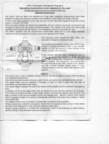
-
4.
REMOTE
CONTROL
CONNECTIONS
-
This
unit
is
controlled
via
a
remote
console.
A
20-socket
receptacle,
located
on
the
front
panel,
is
provided
for
making
connections
between
the
remote
control
and
the
power
source.
Insert
the
plug
from
the
remote
con
trol
fully
into
the
receptacle
and
rotate
the
locking
ring
clockwise.
d.m.g.
torch.
Current
transformer
jumper
links
on
terminal
strip
I
T
located
on
center
baffle
must
be
positioned
to
correspond
with
secondary
open-c,,cuif
voltage.
Pilot
Light
Circuit
Breaker
Remote
Figure
3-1.
Weld
Output
Connections
80
O.C.V.
I~ 'I
I~
'I
1~
~1
i~
~1 1'
~1
I~
~1
'~'_~I~
'~
~
160
O.C.V.
80OC.V~
160
OC.V.
CURRENT
TRANSFORMER
_______
JUMPER
p078
~073
074
/079
~071
075
~Q8O
~072
076
CAUTION
078
~074
079
071
~075
Oeo
p072
~07e
IMPROPER
SECONDARY
CONNECTIONS
can
Figure
3
-
2.
Open-Circuit
Voltage
Connections
TA.093
943
1235
16
Page
9

3
-
5.
ELECTRICAL
INPUT
CONNECTIONS
Table
3-2.
Input
Conductor
And
Fuse
Size
A.
Electrical
Input
Requirements
This
power
source
is
designed
to
be
operated
from
three-phase,
60
Hertz,
ac
input
power
which
has
a
voltage
rating
that
corresponds
with
one
of
the
elec
trical
input
voltages
shown
on
the
nameplate.
Consult
the
local
electric
utility
if
there
is
any
question
about
the
type
of
electrical
system
available
at
the
installation
site
or
how
proper
connections
to
the
power
source
are
to
be
made.
B.
Matching
the
Welding
Power
Source
To
The
Available
Input
Voltage--Multiple
Voltage
Models
Only
This
unit
is
equipped
with
input
voltage
jumper
links
on
the
primary
terminal
board
which
allow
operation
from
different
line
voltages.
This
unit
is
shipped
with
jumper
links
positioned
for
the
highest
voltage
stated
on
the
nameplate.
If
the
unit
is
to
be
operated
from
a
lower
in
put
voltage,
remove
the
top
cover
and
reposition
the
jumper
links
to
correspond
to
the
available
line
voltage
(see
input
voltage
label
on
primary
terminal
board).
(S1..1LuiU~~E
INCORRECT
INPUT
VOLTAGE
JUMPER
LINK
PLACEMENT
can
damage
unit.
Position
jumper
links
as
shown
on
the
input
voltage
label
located
on
primary
terminal
board.
IMPORTANT
ed
terminals.
Store
unused
jumper
links
across
link-
C.
Input
Conductor
Connections
WARNING
_________
ELECTRIC
SHOCK
can
kill.
It
is
recommended
that
a
fusible
line
disconnect
switch
be
installed
in
the
input
circuit
to
the
power
source.
This
would
provide
a
safe
and
convenient
means
to
completely
remove
all
electrical
power
from
the
power
source
whenever
it
is
necessary
to
internally
inspect
or
service
the
unit.
Employ
lockout/tagging
procedures
on
input
line
before
making
input
connections
to
the
power
source.
Lockout/tagging
procedures
consist
of
padlocking
line
disconnect
switch
in
o~5~n
position,
removing
fuses
from
fuse
box,
or
tagging
circuit
breaker
or
other
disconnecting
device.
Connect
input
conductors
to
the
power
source
before
connecting
to
three-phase
input
power.
Table
3-2
provides
guidelines
for
selecting
the
proper
size
input
conductors
and
line
fuses.
The
input
conduc
tors
should
be
covered
with
an
insulating
material
that
meets
local
electrical
standards.
Attach
terminal
lugs
to
correct
amperage
capacity
to
the
input
and
ground
conductors.
The
hole
diameter
in
the
terminal
lug
must
be
the
correct
size
to
fit
the
line
and
ground
terminal
studs.
L
Iflp~5
Conduc~o,
S,pe-
AW(3.
F,e.
See
In
Amps,s.
200V
230
380V
440V
460V
575V
200V
230V
380V
440V
460V
575r~
I
1360
UCU
300
MCM
2/0
1/0 No.
I
No
2
No.
2)
(No.
4)
(No.
6)
(NO.
6/
(No.
6
500
400
260
200
200
175
PS-2000
Models
Input
COnducto,
Si,.
-
AWG.
Fuse
S.,,
In
Amperes
200V
230V
38SV
440V
460V
575V
200V
2300
380V 440V
4600
075V
315
2/0
No.3
No.4
NO.4 No.6
No
4)
No
4/
(No.
SI
(No.
6)
No.
6/
(No.
8/
250
025
125 110
IS
90
PS-1005
Models
0lnput
conductor
sizes
are
based
on
National
Electrical
Code
specifications
for
allowable
ampacities
of
in
sulated
copper
conductors,
having
a
temperature
rating
of
75C,
with
not
more
than
three
conductors
in
a
raceway
or
cable.
Numbers
in
(
I
are
equipment
ground
conductor
sizes.
Insert
the
three
input
conductors
plus
one
ground
con
ductor
through
the
access
hole
on
the
left
side
panel.
This
hole
will
accept
standard
conduit
fittings.
See
Figure
3-4
for
hole
location.
WARNING:
_____
ELECTRIC
SHOCK
can
kill.
Do
not
connect
an
input
conductor
to
the
ground
terminal
in
the
unit.
Do
not
connect
the
ground
conductor
to
an
input
line
terminal.
Incorrect
input
connections
can
result
in
an
electrically
energized
power
source
chassis.
The
ground
termjpal
is
connected
to
the
power
source
chassis
and
is
for
groun
ding
purposes
only.
Connect
the three
input
conductors
to
the
line
terminals
on
the
primary
terminal
board
and
connect
the
ground
conductor
to
the
ground
terminal.
The
remaining
end
of
the
ground
conductor
should
be
connected
to
a
proper
ground.
Use
a
grounding
method
that
is
acceptable
to
the
local
electrical
inspection
authority.
Voltage
Selection
Board
Location
(If
Applicable)
With
Jumper
Links
Primary
\
TerminaI~
Board
input
Conductor
Access
Hole
Current
Transformer
Changeover
Strip
iT
Open
Circuit
Voltage
Changeover
Board
Figure
3-4.
Input
Conductor
Connections
123516
Page
10

SECTION
4
-
OPERATOR
CONTROLS
4-1.
PILOTLIGHT(Figure3-1)
-
ThepilotlightPLl
is
wired
in
parallel
with
contactor
W
coil
and
indicates
when
the
contactor
is
energized.
4
-
2.
VOLT-AMPERE
CURVES
(Figures
4-1
and
4-2)
-
The
volt-ampere
curves
show
the
voltage
and
amperage
output
capabilT~ies
of
the
power
source
at
mm.
and
max.
of
each
coarse
range.
Voltage
and
amperage
adjustment
within
each
range
is
provided
by
the
Amperage
Adjustment
control.
4,
6.
a
z
a
MOD(L
PS-2O~
8084
009
Chart
For
PS-2000
4,
$.0
a
Figure
4
-
2.
Duty
Cycle
Models
9706
606
(3009
ROGOJ
I
._
~
,~
,I~
DC
AMPERES
Figure
4-1.
1000
900
600
700
600
500
400
-
6~S~5
64
(606
56
0
601
6
6~GE
-
~.,
8084
007
Volt-Ampere
Curves
For
PS-2000
Models
30
7500
0
(00*
$009
6690)
$000
0
001
(4070
POMSO)
8.116
Rh
40
20
~Q
60
70
I
4,777
90
00
CAUTION
7
00
207
300
400
500 bOO
:00
600
000
.00
X
006765
Figure
4
-
3.
Duty
Cycle
Chart
For
PS-1005
Models
With
the
use
of
the
volt-ampere
curves
it
is
possible
to
determine
the
load
voltage
at
any
particular
weld
cur
rent.
EXCEEDING
DUTY
CYCLE
RATING
will
damage
the
power
source.
-
Do
not
exceed
duty
cycles
indicated
on
duty
cycle
chart.
4
-
4.
115
VOLTS
AC
DUPLEX
RECEPTACLE
(Figure
3-1)
-
The
duplex
receptacle
is
provided
for
running
accessory
equipment.
Up
to
10
amperes
of
11
5
volts
ac,
60
Hertz
power
is
available
at
the
receptacle.
8116
832
Figure
4
-
2.
Volt-Ampere
Curves
For
PS-1005
4
-
5.
OVERLOAD
PROTECTION
(Figure
3-1)
-
The
unit
is
protected
from
damage
caused
by
an
Models
overload
by
circuit
breaker
CB.
When
an
overload
oc
curs
CB
opens,
dropping
Out contactor
W
thereby
4
-
3.
DUTY
CYCLE
(Figures
4-3
And
4-4)
-
The
du-
suspending
output.
CB
must
be
manually
reset.
.
ty
cycle
of
a
power
source
is
the
percentage
of
a
ten
minute
period
that
the
unit
can
be
safely
operated
at
a
The
control
transformers
T2
and
T3
are
protected
by
fuses
Fl,
F2.
and
F3,
located
on
the
center
baffle.
If
an
given
output.
These
units
are
rated
at
100
percent
duty
cycle.
This
means
that
they
can
be
safely
operated
at
rated
load
continuously.
Figures
4-3
and
4-4
enable
the
overload
occurs,
the
appropriate
fuse
opens,
suspen
ding
output.
operator
to
determine
the
safe
output
of
each
unit
at
various
duty
cycles,
Be
sure
the
replacement
fuse
is
of
the
same
size,
type,
and
rating
as
the
fuse
being
replaced.
IMPORTANT
123516
Page
11

SECTION
5
-
SEQUENCE
OF
OPERATION
f~1:h~II~c~
ELECTRIC
SHOCK
can
kill;
MOVING
PARTS
can
cause
serious
injury;
IMPROPER
AIR
FLOW
AND
EXPOSURE
TO
ENVIRONMENT
can
damage
internal
parts.
Keep
all
covers
arid
pane/s
in
p/ace
while
operating.
Warranty
is
void
if
the
power
source
is
operated
with
any
portion
of
the
outer
enclosure
removed.
ARC
RAYS.
SPARKS.
AND
HOT
SURFACES
can
burn
eyes
and
skin;
NOISE
can
damage
hearing.
Wear
correct
eye,
ear,
and
body
protection.
FUMES
AND
GASES
can
seriously
harm
your
health.
Use
enough
ventilation
to
keep
fumes
and
gases
from
the
breathing
zone.
WARNING
See
Section
1
-
Safety
Rules
For
Operation
Of
Arc
Welding
Power
Source
for
basic
welding
safety
infor
mation.
1.
Ensure
that
the
unit
has
been
installed
as
in
structed
in
Section
3.
2.
Connect
desired
accessory
equipment
to
the
115
VOLTS
AC
duplex
receptacle.
3.
Set
the
controls
on
the
remote
control.
4.
Energize
the
power
source
and
associated
equip
ment.
IMPORTANT
Before
shutting
down,
remove
the
load
and
allow
the
unit
to
idle
for
a
few
minutes.
SECTION
6
-
MAINTENANCE
WARNING
__________
ELECTRIC
SHOCK
can
kill.
Disconnect
input
power
and
employ
lockout!
tagging
procedures
before
internally
inspecting
or
servicing.
Lockout/tagging
procedures
consist
of
padlocking
line
disconnect
switch
in
open
position,
removing
fuses
from
fuse
box,
or
tagging
circuit
breaker
or
other
disconnecting
device.
IkAI
~ui
:
f~
~
I
~
Periodically
inspect
the
labels
on
this
unit
for
legibility.
All
labels
must
be
maintained
in
a
clearly
readable
state
and
replaced
when
necessary.
See
the
Parts
List
for
part
number
of
labels.
6
-
1.
FAN
MOTOR
-
This
unit
is
equipped
with
an
exhaust
fan
and
relies
on
forced
draft
for
adequate
cool
ing.
The
fan
motor
is
manufactured
with
lifetime
sealed
bearings
and
requires
no
maintenance.
6
-
2.
INTERNAL
CLEANING
-
Occasional
blowing
Out
or
vacuuming
of
the
dust
and
dirt
from
around
the
internal
components
is
recommended.
This
should
be
done
periodically
depending
on
the
location
of
the
unit
and
the
amount
of
dust
and
dirt
in
the
atmosphere.
The
welding
power
source
outer
enclosure
should
be
remov
ed
and
a
clean,
dry
airstream
or
vacuum
suction
should
be
used
for
this
cleaning
operation.
6
-
3.
SPARK
GAPS
(Figure
6-1)
-
It
is
necessary
to
readjust
the
spark
gaps
every
three
to
four
months
or
when
intermittent
operation
occurs.
High-frequency
output
varies
with
the
spark
gap
set
ting.
When
a
great
~amount
of
high
frequency
is
necessary,
the
spark
gaps
can
be
adjusted
to
0.010
in.
to
0.013
in.
(0.254
to
0.330
mm).
This,
however,
in
creases
high-frequency
radiation
which
increases
in
terference
with
communications
equipment.
IMPORTANT
______________
Do
not
clean
or
dress
the
points
of
the
spark
gaps
because
the
material
at
the
points
is
tungsten
and
is
impossible
to
file.
Rep/ace
the
entire
point
when
the
tungsten
sect/on
has
completely
disap
peared.
The
high
frequency
panel
is
located
behind
the
left
side
panel.
To
adjust
the
spark
gaps,
proceed
as
follows:
1.
Loosen
screws
A
on
both
sides.
2.
Place
feeler
gauge
of
proper
thickness
between
points
C.
3.
Apply
slight
pressure
against
points
B
so
feeler
gauge
is
held
firmly
in
gap.
4.
Tighten
screws
A.
Figure
6-1.
Spark
Gap
Adjustment
TA-020
623-A2
123516
Page
12

SECTION
7
-
TROUBLESHOOTING
I1:l~II~L~
ELECTRIC
SHOCK
can
kill.
Do
not
touch
live
electrical
parts.
Disconnect
unit
from
input
power
before
internal
iy
inspecting
or
servicing.
MOVING
PARTS
can
cause
serious
injury.
Keep
c/ear
of
moving
parts.
HOT
SURFACES
can
cause
severe
burns.
Allow
cooling
period
before
servicing.
Troubleshooting
of
internal
parts
to
be
performed
only
by
qualified
persons.
The
following
chart
is
designed
to
diagnose
and
provide
remedies
for
some
of
the
troubles
that
may
develop
in
this
power
source.
It
is
assumed
that
proper
installation
has
been
made,
ac
cording
to
Section
3
of
this
manual,
and
that
the
power
source
has
been
functioning
properly
until
this
trouble
develped.
Use
this
chart
in
conjunction
with
the
circuit
diagram
while
performing
troubleshooting
procedures.
If
the
trouble
is
not
remedied
after
performing
these
pro
cedures,
the
nearest
Factory
Authorized
Service
Sta
tion
should
be
contacted.
In
all
cases
of
equipment
malfunction,
the
manufacturers
recommendations
should
be
strictly
followed.
TROUBLE
PROBABLE
CAUSE
REMEDY
Completely
inoperative.
No
power
output.
Check
position
of
line
disconnect
switch.
Open
line
fuse(s)
and/or
circuit
breaker(s).
Replace
the
fuse(s)
and/or
reset
circuit
breaker(s).
Poor
and/or
improper
input
connections.
Refer
to
Section
3-5
for
proper
input
connections.
No
output.
Poor
or
improper
Remote
Control
connections.
Check
remote
control
connections
(see
Section
3-4).
Printed
circuit
card
PCi
in-
operative
or
loose
in
edge
connector.
Check
printed
circuit
card
PCi
connection.
If
PCi
loose
in
connector,
tighten.
If
PCi
inoperative,
replace.
Limited
output
and
low
open-circuit
voltage.
Operation
on
single-phase.
Open
line
fuse
on
one
phase.
Check
incoming
three-phase
power
for
correct
voltage.
Replace
fuse
if
open.
Poor
and/or
improper
input
and/or
secondary
connec-
tioflS.
Refer
to
Section
3-5
and
3-2
for
proper
input
and
secondary
connections.
Erratic
current.
Incorrect
secondary
cable
size.
Use
proper
size
and
type
of
cable.
See
Section
3-2.
Loose
secondary
cable
con-
nection.
Tighten
all
welding
connections.
SCR
in
main
rectifier
SRi.
Replace
SCR.
Printed
circuit
card
PCi.
Replace
printed
circuit
card
PCi.
123516
Page
13

r)
0)
-u
0
4SO
V
ONLY
1,
GRO
I
A
B
NEGATIVE
Figure
7
-
1.
Circuit
Diagram
For
PS-2000
Models
Circuit
Diagram
No.
C-114
623

N)
C.)
U
0)
-o
Figure
7
-
2.
Circuit
Diagram
For
PS-1005
Models
(Il
pos1
I
lyE
RFC
NEGA
FIVE
15
Circuit
Diagram
No.
C-115
040

W2
THIS
PRIMARY
REPLACES
THAT
AROVE
Circuit
Diagram
No.
A-098
879
Figure
7
-
3.
Primary
Circuit
Diagram
For
PS-2000
And
PS-1005
Models
123516
Page
16
/