Page is loading ...

OPERATION MANUAL
EL-42PIP
4 x 2 HDMI Switch with Integrated Multi-View
(Picture In Picture) Technology


3
DISCLAIMERS
The information in this manual has been carefully checked and is
believed to be accurate. CYP (UK) Ltd assumes no responsibility for any
infringements of patents or other rights of third parties which may result
from its use.
CYP (UK) Ltd assumes no responsibility for any inaccuracies that may be
contained in this document. CYP (UK) Ltd also makes no commitment to
update or to keep current the information contained in this document.
CYP (UK) Ltd reserves the right to make improvements to this document
and/or product at any time and without notice.
COPYRIGHT NOTICE
No part of this document may be reproduced, transmitted, transcribed,
stored in a retrieval system, or any of its part translated into any language
or computer file, in any form or by any means—electronic, mechanical,
magnetic, optical, chemical, manual, or otherwise—without express
written permission and consent from CYP (UK) Ltd.
© Copyright 2011 by CYP (UK) Ltd.
All Rights Reserved.
Version 1.1 August 2011
TRADEMARK ACKNOWLEDGMENTS
All products or service names mentioned in this document may be
trademarks of the companies with which they are associated.

4
SAFETY PRECAUTIONS
Please read all instructions before attempting to unpack, install or operate
this equipment and before connecting the power supply.
Please keep the following in mind as you unpack and install this
equipment:
• Always follow basic safety precautions to reduce the risk of fire,
electrical shock and injury to persons.
• To prevent fire or shock hazard, do not expose the unit to rain,
moisture or install this product near water.
• Never spill liquid of any kind on or into this product.
• Never push an object of any kind into this product through any
openings or empty slots in the unit, as you may damage parts inside
the unit.
• Do not attach the power supply cabling to building surfaces.
• Use only the supplied power supply unit (PSU). Do not use the PSU if
it is damaged.
• Do not allow anything to rest on the power cabling or allow any
weight to be placed upon it or any person walk on it.
• To protect the unit from overheating, do not block any vents or
openings in the unit housing that provide ventilation and allow for
sufficient space for air to circulate around the unit.
REVISION HISTORY
VERSION NO. DATE SUMMARY OF CHANGE
v1.00 10/03/2018 First release
v2.00 17/10/2018 Added section 8.2.2 and updated
Section 6.6, 6.7.3 (Matrix Mode)

5
CONTENTS
1. Introduction ...........................................6
2. Applications ...........................................6
3. Package Contents ..................................6
4. System Requirements ...........................7
5. Features ..................................................7
6. Operation Controls and Functions .......8
6.1 Front Panel ................................................... 8
6.2 Rear Panel ..................................................... 9
6.3 Remote Control ........................................ 10
6.4 RS-232 Control .......................................... 11
6.5 Telnet Control ............................................12
6.6 RS-232 and Telnet Commands ............ 13
6.7 WebGUI Control .......................................25
7. Connection Diagram .......................... 42
8. Specifications ...................................... 43
8.1 Technical Specifications ........................43
8.2 Video Specifications................................44
9. Acronyms ............................................. 46

6
1. INTRODUCTION
This 4 by 2 Multiviewer is a high performance HDMI switch with
integrated scaling and multi-windowing technology. It is an ideal solution
for monitoring or displaying multiple sources simultaneously for use in
control rooms, conference rooms or classrooms. Video resolutions up to
4K@60Hz and LPCM audio up to 7.1 channels at 192kHz are supported on
both input and output and this unit is fully compatible with the HDCP 1.x
and 2.2 standards.
Any of 4 different HDMI sources may be displayed individually, full
screen, or they can be displayed using a variety of multi-window modes
including quad view and PiP with the output being sent to 2 mirrored
HDMI outputs (4K@50/60Hz output supports quad view and full screen
only). Management of input/window routing, position and sizing can be
controlled easily by use of the front panel controls as well as by WebGUI,
RS-232, Telnet, and IR remote control options.
2. APPLICATIONS
Entertainment Room & Home Theatre
Show Room & Demo Room
Lecture Room & Hall Presentation
Public Commercial Display
3. PACKAGE CONTENTS
1×4 by 2 HDMI Multiviewer
1×12V/3A DC Power Adapter
2×5-pin Terminal Block
1×Remote Control (CR-180)
1×Rackmount Ears (Set of 2)
1×Operation Manual

7
4. SYSTEM REQUIREMENTS
HDMI source equipment such as media players, video game consoles
or set-top boxes.
HDMI receiving equipment such as HDTVs, monitors or audio
ampliers.
5. FEATURES
HDMI inputs and outputs with 18Gbps (600MHz) 4K UHD support
DVI 1.0 compatible with the use of an HDMI-DVI adaptor
HDCP 1.x and 2.2 compliant
Supports HD resolutions up to 4K@60Hz (4:4:4, 8-bit)
4 HDMI inputs and 2 mirrored HDMI outputs
Seamless switching (no loss of sync to display) when switching
sources in both full screen and multi-window modes
Supports PiP (Picture-in-Picture), side by side, 3+1 quad view, and 2×2
quad view display options with independent audio source selection
Note: 4K@50/60Hz output supports 2×2 Quad View only and is limited to
1080p/4K sources.
Supports the ability to store a multi-window arrangement as a preset
that can be recalled later
Each window can have a border with a selectable colour
Uploadable and freely positioned graphic logo support
Note: The logo and border features are not available when the output is set
to 4K@50/60Hz.
Supports easy adjustment of window size, position and settings in the
PiP windowing mode via the WebGUI
Matrix mode supports input and output resolutions up to
1080p@60Hz with a single shared audio source (Outputs are mirrored
at higher resolutions)
Controllable via front panel buttons, WebGUI, Telnet, RS-232, and IR
remote

8
6. OPERATION CONTROLS AND FUNCTIONS
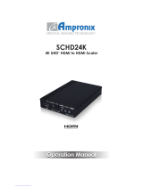
6.1 Front Panel
POWER
A
B
IN 1 IN 2 IN 3 IN 4
MATRIX
1234
MULTI VIEW
WINDOW SOURCE SELECT
W1 W2 W3 W4
1234
12
3
4
2
1
1
2
1
2
3
4
MENU LOCK
ENTER PRESET
+
-
EL-42PIP
1 2 53
4 6
7 8 10 11
9
1
POWER: Press this button to power the unit on (green LED) or place it
into stand-by mode (red LED).
2
IR WINDOW: Accepts IR signals from the included IR remote for
control of this unit only.
3
MATRIX A/B IN1~IN4: These input selection buttons behave
differently depending on the current input and output resolutions in
use.
A
All inputs and outputs are below 4K: Press any of these buttons to
seamlessly switch to the selected input (IN1~IN4)for display on the
associated output (A or B).
B
Any input or output is 4K: Press any of these buttons to seamlessly
switch to the selected input (IN1~IN4) for display on both outputs
simultaneously.
Note: Audio for both outputs will follow the most recently selected input
(from A or B) in both modes.
4
MULTIVIEW: Press any of these buttons to switch immediately to the
corresponding Multiview output mode.
5
WINDOW SOURCE SELECT: Press these buttons to sequentially
switch through the available inputs for each window in Multiview
output modes.
6
MENU: Press to enter the LCD menu, or to back out from menu Items.
7
ENTER: Press to confirm a selection within the LCD menu or to go
deeper into a menu item.
8
+ & −: Press to move up and down or adjust selections within menus.
9
LOCK: Press to lock all button functions on the front panel. Press the
button again to release the lock function. The LCD will display a “Lock”
message when the function is active.

9
10
PRESET: Press this button to switch between the “Preset Load” and
“Preset Save” modes. Pressing the button a 3rd time exits the Preset
menu.
A
Preset Save: When in “Preset Save” mode, pressing the “Enter” button
will save the currently displayed window layout.
B
Preset Load: When in the “Preset Load” mode, pressing the “Enter”
button will load the previously saved window layout.
Note: The audio selection is not saved as a part of the preset, only the
window layout.
11
LCD WINDOW: Displays the unit’s menu, settings, and information.
6.2 Rear Panel
DC 12V
CONTROL SERVICE
GND
TX
RX
RTS
CTS
COM
G
L/R OUT
-
+
-
+
AB
HDMI OUT
1 234
HDMI IN
1 2 4
3
5 6 7
1
HDMI IN 1~4: Connect to HDMI source equipment such as media
players, game consoles or set-top boxes. DVI source equipment may
be connected by using an HDMI to DVI adapter.
2
HDMI OUT A~B: Connect to HDMI TVs, monitors or amplifiers for
digital video and audio output. DVI display equipment may be
connected by using HDMI to DVI adapter.
3
L/R OUT: Connect to powered speakers or an amplifier using a 5-pin
adapter cable for balanced stereo analogue audio output.
Note: Only LPCM 2.0 sources are supported. Bitstream audio sources will
be muted automatically.
4
COM: Connect directly to a PC, laptop or other serial control device
with a 3-pin adapter cable to send RS-232 commands to control the
unit.
5
CONTROL: Connect directly, or through a network switch, to your PC/
laptop to control the unit via Telnet/WebGUI.
6
SERVICE: This slot is reserved for firmware update use only.
7
DC 12V: Plug the 12V DC power adapter into the unit and connect it
to an AC wall outlet for power.

10
6.3 Remote Control
1
POWER: Power on the machine or enter to
standby mode.
2
INFO: Display the current status/
information of the unit.
3
A1~A4 & B1~B4: (Matrix Selection)
A
When all inputs and outputs are
below 4K: Press any of these buttons to
seamlessly switch to the selected input
(1~4) for display on the associated output
(A or B).
B
When any input or output is 4K: Press
any of these buttons to seamlessly switch
to the selected input (1~4) for display on
both outputs simultaneously.
Note: Audio for both outputs will follow the most recently selected input
(from A or B) in both modes.
4
MV1~MV4: (Multiview Selection) Press these buttons to switch
immediately to the corresponding Multiview output mode.
MV1: Switch to 2×2 quad view mode.
MV2: Switch to the 3+1 quad view mode.
MV3: Switch to the side-by-side view mode
MV4: Switch to PiP view mode.
5
MATRIX/MULTIVIEW: Press to toggle between the Matrix and
Multiview modes.
6
LOCK: Press to lock all button functions on the front panel. Press the
button again to release the lock function.
7
ARROWS (
/
/
/
) & OK: Press the arrow buttons to navigate
the LCD menu. Press the “OK” button to confirm a selection or to go
deeper into a menu item.
8
MENU: Press to enter the LCD menu.
9
EXIT: Press to exit out of the current LCD menu item.
10
W1~W4: (Window Source Selection) Press these buttons to
sequentially switch through the available inputs for each window (1~4)
in Multiview output modes.
INFO POWER
A1 B1
A2 B2
A3 B3
A4 B4
MV1
MV2
MV3
MV4
LOCK
MATRIX/
MULTI VIEW
EXIT MENU
OK
SAVE
PRESET
W1
W2
W3
W4
SOURCE
MUTE
UP
DOWN
AUDIO
CR-180
2
3
11
6
9
10
1
4
5
7
8
12

11
11
SAVE: Pressing this button will save the currently displayed window
layout.
PRESET: Pressing this button will load the previously saved window
layout.
12
SOURCE: Press this button to sequentially switch through the
available audio sources.
MUTE: Press to toggle between muting and unmuting the audio
output.
UP: Press this button to increase the audio output volume.
DOWN: Press this button to decrease the audio output volume.
Note: The volume controls only affect the analogue audio output.
6.4 RS-232 Control
UNIT TERMINAL SERIAL PORT SETTINGS
Pin Pinout Pin Pinout Baud Rate 19200
1 GND 1 Data Bits 8
2 TX 2 RxD Parity Bits None
3 RX 3 TxD Stop Bits 1
4 RTS 4 Flow Control None
5 CTS 5 GND
6
7
8
9

12
6.5 Telnet Control
Before attempting to use Telnet control, please ensure that both the unit
and the PC are connected to the same active networks.
To Access the Command Line Interface (CLI)
Windows 7 Click Start, type “cmd” in the search eld, and press
Enter.
Windows XP Click Start > Run, type “cmd”, and press Enter.
Mac OS X Click Go > Applications > Utilities > Terminal.
Once in the Command Line Interface (CLI) type “telnet” followed by the
IP address of the unit (and the port number if it is non-standard) and then
hit “Enter”. This will connect us to the unit we wish to control. Type “help”
to list the available commands. See below for reference.
Note: If the IP address is changed then the IP address required for Telnet
access will also change accordingly.

13
6.6 RS-232 and Telnet Commands
6.6.1 Basic Commands
COMMAND
DESCRIPTION VARIABLES
HELP
Show the full command list.
?
Show the full command list.
GET FW VER
Show the current firmware version.
GET MODEL NAME
Show the model name.
GET MODEL TYPE
Show the model type.
SET FACTORY DEFAULT
Reset the unit to its factory defaults.
SET POWER N1
Turn the unit on or off (standby). Available values for N1:
ON [Power on]
STANDBY [Standby mode]
GET POWER
Show the current power state.
SET SYSTEM REBOOT
Reboot the unit.
SET KEYLOCK N1
Enable or disable the front panel key
lock.
N1 = ON, OFF [Front panel lock state]
GET KEYLOCK
Show the current front panel lock state.

14
6.6.2 Ethernet Configuration
COMMAND
DESCRIPTION VARIABLES
GET MAC 1 ADDR
Show the unit’s MAC address.
SET IP MODE N1
Set the IP mode of the unit. Available values for N1:
STATIC [Static IP mode]
DHCP [DHCP mode]
GET IP MODE
Show the current IP mode.
GET IPCONFIG
Show the current IP configuration.
SET IPADDR N1
Set the unit’s static IP address. N1 = X.X.X.X [X = 0~255, IP address]
GET IPADDR
Show the current IP address.
SET NETMASK N1
Set the unit’s netmask address. N1 = X.X.X.X [X = 0~255, Netmask]
GET NETMASK
Show the current netmask.
SET GATEWAY N1
Set the unit’s gateway address. N1 = X.X.X.X [X = 0~255, Gateway]
GET GATEWAY
Show the current gateway address.

15
6.6.3 Video Commands
COMMAND
DESCRIPTION VARIABLES
SET IN N1 NAME N2
Set the name for input N1. N1 = 1~4 [Input number]
N2 = {name} [24 characters max]
GET IN N1 NAME
Show the name of input N1. N1 = 1~4 [Input number]
SET OUT N1 NAME N2
Set the name for output N1. N1 = A~B [Output letter]
N2 = {name} [24 characters max]
GET OUT N1 NAME
Show the name of output N1. N1 = A~B [Output letter]
SET OUT N1 ROUTE N2
Set the routing source for output N1
and switch to matrix mode.
N1 = A~B [Output letter]
N2 = 1~4 [Input number]
GET OUT N1 ROUTE
Show the matrix mode routing source
for output N1.
N1 = A~B [Output letter]
SET PRESET 1 SAVE
Save the current video layout as a
preset.
SET PRESET 1 LOAD
Load the saved video layout preset.

16
6.6.4 Scaler Commands
COMMAND
DESCRIPTION VARIABLES
SET DISPLAY MODE N1
Set the unit’s output mode. Available values for N1:
0 [Matrix mode]
1 [Multiviewer mode]
GET DISPLAY MODE
Show the unit’s current output mode.
SET OUT A TIMING N1
Set the output resolution and timing to
use for both outputs.
Available values for N1:
0 [Native (Output A)]
1~36 [Output resolution]
Timing Codes:
0 = Native
1 = 640×480
2 = 480p@60
3 = 576p@50
4 = 800×600
5 = 848×480
6 = 1024×768
7 = 720p@50
8 = 720p@60
9 = 1280×768
10 = 1280×800
11 = 1280×960
12 = 1280×1024
13 = 1360×768
14 = 1366×768
15 = 1400×1050
16 = 1440×900
17 = 1600×900 (RB)
18 = 1600×1200
19 = 1680×1050
20 = 1080i@50
21 = 1080i@60
22 = 1080p@24
23 = 1080p@25
24 = 1080p@30
25 = 1080p@50
26 = 1080p@60
27 = 1920×1200 (RB)
28 = 2048×1152 (RB)
29 = 3840×2160p@24
30 = 3840×2160p@25
31 = 3840×2160p@30
32 = 4096×2160p@24
33 = 4096×2160p@25
34 = 4096×2160p@30
35 = 3840×2160p@50
36 = 3840×2160p@60

17
6.6.4 Scaler Commands
COMMAND
DESCRIPTION VARIABLES
GET OUT A TIMING
Show the current output resolution
timing.
SET WINDOW LAYOUT MODE N1
Set the multiview window layout mode
and switch to multiview mode.
Available values for N1:
1 [2×2 quad view]
2 [3+1 quad view]
3 [Side-by-Side]
4 [Picture-in-Picture]
GET WINDOW LAYOUT MODE
Show the current window layout mode.
SET WINDOW N1 LAYOUT MODE N2 ASPECT RATIO N3
Set the aspect ratio to use for window
N1 in layout mode N2.
N1 = 1~4 [Window number]
Available values for N2:
2 [3+1 quad view]
3 [Side-by-Side]
Available values for N3:
0 [Full window]
1 [16:9 aspect]
2 [4:3 aspect]
GET WINDOW N1 LAYOUT MODE N2 ASPECT RATIO
Show the aspect ratio currently used
by window N1 in layout mode N2.
N1 = 1~4 [Window number]
Available values for N2:
2 [3+1 quad view]
3 [Side-by-Side]
SET WINDOW N1 ROUTE N2
Set the input routing for the windows
in multiview mode.
N1 = 1~4 [Window number]
N2 = 1~4 [Input number]

18
6.6.4 Scaler Commands
COMMAND
DESCRIPTION VARIABLES
GET WINDOW N1 ROUTE
Show the input currently routed to
window N1.
N1 = 1~4 [Window number]
SET WINDOW N1 BORDER N2
Set the border colour for window N1. N1 = 1~4 [Window number]
Available values for N2:
0 [Off]
1 [Blue]
2 [Green]
3 [Red]
4 [Yellow]
5 [Cyan]
6 [Magenta]
GET WINDOW N1 BORDER
Show the border colour for window N1. N1 = 1~4 [Window number]
SET PIP HSIZE N1
Set the horizontal size of the PiP
window (in pixels).
N1 = 0~? [PiP width]
!
Note: The maximum value depends on, and cannot exceed, the current output
resolution’s width.
GET PIP HSIZE
Show the current horizontal PiP
window size.
SET PIP VSIZE N1
Set the vertical size of the PiP window
(in pixels).
N1 = 0~? [PiP height]
!
Note: The maximum value depends on, and cannot exceed, the current output
resolution’s height.
GET PIP VSIZE
Show the current vertical PiP window
size.

19
6.6.4 Scaler Commands
COMMAND
DESCRIPTION VARIABLES
SET PIP HPOSITION N1
Set the horizontal position of the top
left corner of the PiP window (in pixels).
N1 = 0~? [Horizontal position]
!
Note: The maximum value depends on, and cannot exceed, the current output
resolution’s width minus 1.
GET PIP HPOSITION
Show the current horizontal position of
the PiP window.
SET PIP VPOSITION N1
Set the vertical position of the top left
corner of the PiP window (in pixels).
N1 = 0~? [Vertical position]
!
Note: The maximum value depends on, and cannot exceed, the current output
resolution’s height minus 1.
GET PIP VPOSITION
Show the current vertical position of
the PiP window.

20
6.6.5 OSD Commands
COMMAND
DESCRIPTION VARIABLES
SET OUT A OSD BANNER DISPLAY N1
Enable or disable the OSD info banner. N1 = ON, OFF [Info banner state]
!
Note: Enabling the info banner will automatically disable display of the graphic logo.
GET OUT A OSD BANNER DISPLAY
Show the current state of the OSD info
banner display.
SET OUT A OSD BANNER LOCATION N1
Set the position of the OSD info banner. Available values for N1:
0 [Upper-left]
1 [Middle-left]
2 [Lower-left]
3 [Upper-right]
4 [Middle-right]
5 [Lower-right]
GET OUT A OSD BANNER LOCATION
Show the current position of the OSD
info banner.
SET OUT A INFO LOGO DISPLAY N1
Enable or disable the graphic logo. N1 = ON, OFF [Graphic logo state]
!
Note: Enabling the graphic logo will automatically disable display of the info banner.
GET OUT A INFO LOGO DISPLAY
Show the current status of the graphic
logo display.
SET OUT A INFO LOGO HPOSITION N1
Set the horizontal position of the top
left corner of the graphic logo (in
pixels).
N1 = 0~? [Horizontal position]
!
Note: The maximum value depends on, and cannot exceed, the current output
resolution’s width minus 1.
/