Page is loading ...

M211861EN-D
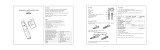
User Guide
Vaisala VaiNet Wireless Data Logger
RFL100

PUBLISHED BY
Vaisala Oyj
Vanha Nurmijärventie 21, FI-01670 Vantaa, Finland
P.O. Box 26, FI-00421 Helsinki, Finland
+358 9 8949 1
Visit our Internet pages at www.vaisala.com.
© Vaisala Oyj 2020
No part of this document may be
reproduced, published or publicly
displayed in any form or by any means,
electronic or mechanical (including
photocopying), nor may its contents be
modified, translated, adapted, sold or
disclosed to a third party without prior
written permission of the copyright holder.
Translated documents and translated
portions of multilingual documents are
based on the original English versions. In
ambiguous cases, the English versions are
applicable, not the translations.
The contents of this document are subject
to change without prior notice.
Local rules and regulations may vary and
they shall take precedence over the
information contained in this document.
Vaisala makes no representations on this
document’s compliance with the local
rules and regulations applicable at any
given time, and hereby disclaims any and
all responsibilities related thereto.
This document does not create any legally
binding obligations for Vaisala towards
customers or end users. All legally binding
obligations and agreements are included
exclusively in the applicable supply
contract or the General Conditions of Sale
and General Conditions of Service of
Vaisala.
This product contains software developed
by Vaisala or third parties. Use of the
software is governed by license terms and
conditions included in the applicable
supply contract or, in the absence of
separate license terms and conditions, by
the General License Conditions of Vaisala
Group.
This product may contain open source
software (OSS) components. In the event
this product contains OSS components,
then such OSS is governed by the terms
and conditions of the applicable OSS
licenses, and you are bound by the terms
and conditions of such licenses in
connection with your use and distribution
of the OSS in this product. Applicable OSS
licenses are included in the product itself
or provided to you on any other applicable
media, depending on each individual
product and the product items delivered
to you.

Table of contents
1. About this document.....................................................................................5
1.1 Version information.......................................................................................... 5
1.2 Related manuals................................................................................................6
1.3 Documentation conventions........................................................................... 6
1.4 Trademarks........................................................................................................ 7
2. Product overview............................................................................................ 8
2.1 RFL100 overview...............................................................................................8
2.1.1 Probe interface...........................................................................................9
2.2 RFL100 parts....................................................................................................10
2.3 RFL100 batteries..............................................................................................12
2.3.1 Battery level indicator..............................................................................12
2.4 Connection indicators..................................................................................... 13
2.4.1 Connection examples.............................................................................. 14
2.5 Signal strength indicator................................................................................ 15
2.6 Alarm indicators.............................................................................................. 16
2.6.1 Alarm examples........................................................................................17
2.7 Service port...................................................................................................... 17
2.7.1 Files and folders in USB filesystem........................................................ 18
2.8 Data transfer in a VaiNet network................................................................. 19
2.9 Safety...............................................................................................................20
2.10 ESD protection............................................................................................... 20
3. Installation........................................................................................................ 21
3.1 Setting up RFL100...........................................................................................21
3.1.1 Setup with one probe.............................................................................. 21
3.1.2 Setup with two temperature probes.....................................................23
3.2 Mounting RFL100........................................................................................... 26
3.3 Mounting probes............................................................................................ 28
3.3.1 Probe holder ASM213382....................................................................... 28
3.3.2 Mounting HMP110 probes.......................................................................29
3.3.3 Mounting HMP115 probes....................................................................... 29
3.3.4 Mounting TMP115 probes....................................................................... 30
4. Operation.......................................................................................................... 31
4.1 Probe detection............................................................................................... 31
4.2 Info mode......................................................................................................... 31
4.2.1 When to use info mode.......................................................................... 32
4.2.2 Turning on info mode..............................................................................32
4.3 Remote management.................................................................................... 33
4.4 Releasing RFL100 from viewLinc Monitoring System............................... 34
4.4.1 Releasing using release button..............................................................35
4.4.2 Releasing remotely using viewLinc.......................................................35
4.5 Vaisala Insight software.................................................................................36
4.5.1 Connecting probe to Insight software.................................................. 37
Table of contents
1

5. Maintenance....................................................................................................38
5.1 Cleaning RFL100.............................................................................................38
5.2 Changing the probe filter.............................................................................. 38
5.3 Probe replacement.........................................................................................39
5.3.1 Probe replacement and viewLinc alarms.............................................39
5.3.2 Replacing a probe when one probe is connected.............................. 40
5.3.3 Replacing probes when two probes are connected........................... 42
5.3.4 Changing from one probe to two probes............................................ 42
5.3.5 Changing from two probes to one probe............................................ 42
5.4 Calibration and adjustment...........................................................................43
5.4.1 Calibration and adjustment environments.......................................... 44
5.4.2 Adjustment points and requirements.................................................. 44
5.4.3 Field checking using a reference instrument.......................................45
5.4.4 Calibration and adjustment using HM40............................................. 45
5.4.5 Calibration and adjustment using MI70............................................... 50
5.4.6 Adjusting measurement using Insight software..................................52
5.5 Changing RFL100 batteries...........................................................................53
5.6 Changing RFL100 clock battery................................................................... 54
5.7 Updating RFL100 firmware...........................................................................54
6. Troubleshooting............................................................................................ 56
6.1 Problem situations......................................................................................... 56
6.2 Error codes...................................................................................................... 57
6.3 Verifying operation of RFL100......................................................................59
6.4 Downloading data using service port..........................................................59
6.5 Performing a factory reset............................................................................ 59
7. Technical data................................................................................................. 61
7.1 RFL100 technical specification...................................................................... 61
7.2 RFL100 compatible probes technical specification................................... 63
7.3 Accessories and spare parts......................................................................... 66
7.4 Dimension drawings.......................................................................................68
Technical support.............................................................................................71
Warranty............................................................................................................. 71
Recycling............................................................................................................ 71
RFL100 User Guide M211861EN-D
2

List of figures
Figure 1 Connecting RFL100 to the viewLinc Monitoring System....................... 8
Figure 2 Front and display............................................................................................. 10
Figure 3 Under the silicone plug.................................................................................. 10
Figure 4 Rear and inside.................................................................................................. 11
Figure 5 Mounting bracket..............................................................................................11
Figure 6 Alarm indicators on RFL100 display...........................................................16
Figure 7 RFL100 with high alarm active on channel 1.............................................17
Figure 8 RFL100 with high-high alarm active on channel 1.................................. 17
Figure 9 Detection of a new RH + T probe................................................................22
Figure 10 RFL100 mounting methods......................................................................... 26
Figure 11 Probe holder ASM213382 parts...................................................................28
Figure 12 HMP110 probe in probe holder ASM213382............................................. 28
Figure 13 HMP110 probe...................................................................................................29
Figure 14 HMP115 probe...................................................................................................29
Figure 15 TMP115 probe................................................................................................... 30
Figure 16 Detection of a new RH + T probe shown on display.............................. 31
Figure 17 RFL100 remote management using viewLinc Enterprise Server...... 33
Figure 18 RFL100 device properties in viewLinc...................................................... 34
Figure 19 HMP115 probe in Insight software...............................................................36
Figure 20 Connecting probe to insight........................................................................ 37
Figure 21 Adjusting relative humidity measurement in Insight............................ 52
Figure 22 RFL100 dimensions with mounting bracket............................................68
Figure 23 RFL100 dimensions without mounting bracket..................................... 69
Figure 24 RFL100 mounting bracket dimensions..................................................... 69
Figure 25 HMP110 probe dimensions............................................................................70
Figure 26 HMP115 probe dimensions............................................................................70
Figure 27 TMP115 probe dimensions.............................................................................70
List of figures
3

List of tables
Table 1 Document versions (English)........................................................................... 5
Table 2 Related manuals.................................................................................................. 6
Table 3 Battery level indicator.......................................................................................12
Table 4 Symbols................................................................................................................ 13
Table 5 Connection states.............................................................................................. 13
Table 6 Signal strength indicator..................................................................................15
Table 7 Alarm symbols....................................................................................................16
Table 8 Specifications for a USB power supply........................................................18
Table 9 Files and folders in USB filesystem............................................................... 18
Table 10 Measurement adjustments of RFL100-compatible probes...................44
Table 11 Troubleshooting table......................................................................................56
Table 12 RFL100 error codes...........................................................................................57
Table 13 Wireless................................................................................................................ 61
Table 14 Memory.................................................................................................................61
Table 15 Operating environment...................................................................................62
Table 16 General.................................................................................................................62
Table 17 Mechanical specifications...............................................................................62
Table 18 HMP110/T probe measurement performance........................................... 63
Table 19 HMP115/T probe measurement performance........................................... 64
Table 20 TMP115 probe measurement performance.................................................65
Table 21 HMP110 probe mechanical specifications...................................................65
Table 22 HMP115/T probe mechanical specifications...............................................66
Table 23 TMP115 probe mechanical specifications................................................... 66
Table 24 Accessories......................................................................................................... 66
Table 25 RFL100 spare parts...........................................................................................67
Table 26 HMP110/T probe spare parts.......................................................................... 67
Table 27 HMP115/T probe spare parts.......................................................................... 68
RFL100 User Guide M211861EN-D
4

1. About this document
1.1 Version information
This document provides instructions for installing, using, and maintaining the RFL100 data
logger.
Table 1 Document versions (English)
Document code Date Description
M211861EN-D February 2020 Added content for probe splitter accessory and two probe
operation. Updated technical data chapter and the
following sections:
• Setup with one probe (page 21)
• Probe replacement (page 39)
• Info mode (page 31)
• Performing a factory reset (page 59)
Added sections:
• Mounting probes (page 28)
• Probe holder ASM213382 (page 28)
• Signal strength indicator (page 15)
• Setup with two temperature probes (page 23)
• Replacing a probe when one probe is connected
(page 40)
• Replacing probes when two probes are connected
(page 42)
• Adjustment points and requirements (page 44)
Regulatory compliance statements are now provided in a
separate document AP10 and RFL100 Regulatory
Compliances (M212235EN).
M211861EN-C February 2019 Added TMP115 probe model. Updated technical data
chapter and the following sections:
• Battery level indicator (page 12)
• Calibration and adjustment using HM40 (page 45)
• Updating RFL100 firmware (page 54)
Added sections:
• Files and folders in USB filesystem (page 18)
• Replacing a probe when one probe is connected
(page 40)
• Vaisala Insight software (page 36)
• Adjusting measurement using Insight software
(page 52)
• Performing a factory reset (page 59)
Chapter 1 – About this document
5

Document code Date Description
M211861EN-B July 2018 Added sections Probe interface (page 9) and Releasing
RFL100 from viewLinc Monitoring System (page 34).
1.2 Related manuals
Table 2 Related manuals
Document code Name
M211822EN RFL100 Data Logger Quick Guide
M212235EN AP10 and RFL100 Regulatory Compliances
M211821EN AP10 Access Point Quick Guide
M211860EN AP10 Access Point User Guide
M211820EN viewLinc 5.0 Monitoring System Setup Guide
M212316EN viewLinc 5.1 Monitoring System Setup Guide
M211975EN viewLinc Enterprise Server 5.0 User Guide
M212315EN viewLinc Enterprise Server 5.1 User Guide
1.3 Documentation conventions
Warning alerts you to a serious hazard. If you do not read and
follow instructions carefully at this point, there is a risk of injury or even death.
WARNING!
Caution warns you of a potential hazard. If you do not read and
follow instructions carefully at this point, the product could be damaged or
important data could be lost.
CAUTION!
Note highlights important information on using the product.
Tip gives information for using the product more eciently.
RFL100 User Guide M211861EN-D
6

Lists tools needed to perform the task.
Indicates that you need to take some notes during the task.
1.4 Trademarks
Vaisalaâ and HUMICAPâ are registered trademarks of Vaisala Oyj.
The LoRa
™
name and associated logo are trademarks of Semtech Corporation or its
subsidiaries.
All other product or company names that may be mentioned in this publication are trade
names, trademarks, or registered trademarks of their respective owners.
Chapter 1 – About this document
7

2. Product overview
2.1 RFL100 overview
Vaisala RFL100 data logger is a completely wireless, battery powered data logger. It supports
several types of Vaisala humidity and temperature measurement probes. RFL100 is intended
as a data collection point in a Vaisala viewLinc Monitoring System.
viewLinc
Enterprise Server
AP10
Access Point
RFL100
Data Loggers
VaiNet wireless
>100 m (328 ft) range
NTP Server
Wired
network
Figure 1 Connecting RFL100 to the viewLinc Monitoring System
The wireless connection of RFL100 requires a Vaisala AP10 access point. AP10 can connect up
to 32 loggers to the viewLinc Monitoring System, and you can have up to 8 access points in
range of each other. In a typical indoor space, install the AP10 within 100 meters (328 ft) of the
RFL100. In an open space with line-of-sight and no interfering structures, the range can be
over 500 m (1640 ft). The wireless connection operates on 868 MHz or 915 MHz frequency
band depending on the model.
RFL100 is optimized for low power operation. It reads the probe once a minute, and transmits
measurement data to the access point every four minutes. Because the radio link is not
continuous, remote management actions and system joining status may take some time to be
updated on the display of the data logger.
Before you start installing RFL100 data loggers, install the viewLinc Enterprise
Server and at least one AP10 access point within range of RFL100. This way
RFL100 can immediately discover your access point and join your system.
For more information on viewLinc Monitoring System installation, see viewLinc
Setup Guide.
More information
‣
RFL100 technical specification (page 61)
RFL100 User Guide M211861EN-D
8

2.1.1 Probe interface
The interface between RFL100 and its detachable probe is digital. RFL100 reads the
measurement results from the probe and stores them in its own memory using the following
resolution:
• RH is stored with resolution of 0.1 %RH
• T is stored with resolution of 0.05 K
Storing the measurement samples using this optimized resolution allows smaller storage size
and faster transfer speed. The same resolution is used when the samples are sent and stored to
viewLinc Enterprise Server.
Local display of RFL100 shows the latest measurements using one decimal place.
This does not aect the internal resolution of temperature measurement in any
way.
The detachable probe also contains its own identifying information (such as serial number)
and information about its latest calibration (calibration date and information text string).
RFL100 makes this information available to viewLinc. If the probe is replaced or the calibration
information is changed, the information in viewLinc is automatically updated.
Chapter 2 – Product overview
9

2.2 RFL100 parts
1
2
3
4
5
6
7
8
Figure 2 Front and display
1 Service port connection indicator
2 Battery level indicator
3 Currently measured values
4 Connection indicators
5 Status LED. Blinks green for normal
operation, red for error or alarm.
6 Signal strength of access point
connection
7 Alarm indicators. Alarms are
configured in viewLinc Enterprise
Server software.
8 Detachable probe, or extension cable
1
2
Figure 3 Under the silicone plug
1 Service port (micro-USB)
2 Info button. Push to enable info mode
for one hour, and again to end the info
mode. Info mode cycles through
information screens, and also enables
faster wireless scanning.
RFL100 User Guide M211861EN-D
10

1
2
3
4
5
6
7
8
Figure 4 Rear and inside
1 Type label
2 On/o switch
3 Clock battery
4 Probe orientation mark. When
connecting the probe, line up the
markings on the probe and above the
connector before pushing the probe to
the connector.
5 Humidity and/or temperature sensors
under the filter
6 Release button. Push to release
RFL100 from its current viewLinc
system, and allow it to connect to any
viewLinc system.
7 Main batteries. Use only non-
rechargeable, AA size, 1.5 V alkaline
(LR6) or lithium (FR6) batteries.
8 Battery cover
1
2
5
4
3
2
Figure 5 Mounting bracket
1 6 mm (0.23 inch) hole for hook
mounting
2 Holes for mounting with cable ties
3 Strong magnet (in magnetic mounting
bracket only). Handle with care.
4 Suitable area for attaching labels
5 3.80 mm (0.15 inch) holes for screw
mounting
Chapter 2 – Product overview
11

2.3 RFL100 batteries
Main batteries
RFL100 data logger is powered by two AA size primary (non-rechargeable) batteries with 1.5 V
nominal voltage. Operation of the data logger always requires that compatible batteries with
sucient voltage are in place. When replacing batteries, always use new batteries, not partially
discharged ones. Minimum battery voltage for operation is 2.15 V in series.
Compatible battery types are:
• 1.5 V alkaline batteries, designation IEC-LR6, ANSI 15A. Standard choice for most
applications.
• 1.5 V lithium batteries, designation IEC-FR14505 (FR6), ANSI 15-LF. Typically higher
capacity, better in cold temperatures.
Do not use batteries with a nominal voltage higher than 1.5 V.CAUTION!
Use of rechargeable batteries is not recommended. RFL100 will not charge
batteries even if the service port is connected to a power supply.
Clock battery
RFL100 also has a separate 3 V lithium battery (type CR1/3N button cell) to keep the real-time
clock powered when the device is switched o. This battery is good for 10 years, and should
only be replaced if the data logger display shows the low clock battery error code Err 200.
2.3.1 Battery level indicator
Battery level indicator displays an estimate of the capacity remaining in the main batteries of the
data logger. It is based on typical behavior of alkaline batteries in this application.
Table 3 Battery level indicator
Symbol on display Description
Full batteries.
One quarter of battery capacity used.
Half of the battery capacity used.
Low battery alarm is activated by viewLinc at this level.
Remaining battery capacity is typically enough for 2 … 4 weeks of
normal operation. Replace batteries.
RFL100 User Guide M211861EN-D
12

Symbol on display Description
Battery voltage is too low to support radio communication. Data
logging continues locally for 2 … 4 weeks until battery voltage is
too low. The last bar of the battery symbol is flashing and error
code Err 103 is shown on the display.
Replace batteries immediately.
Battery voltage is too low for operation. Data logging is stopped.
Only the empty battery symbol is shown on the display.
Replace batteries to resume normal operation.
2.4 Connection indicators
Table 4 Symbols
Symbol Description Symbol Description
Data logger Connection OK
Access point Connection currently
unavailable
viewLinc Enterprise Server
Table 5 Connection states
Symbols on display Description
Data logger is searching for an access point.
Data logger has failed to find an access point that is in installation
mode. viewLinc server icon is not shown, as the data logger has
not been accepted to a viewLinc system yet.
The data logger has failed to connect to an access point that
belongs to its own network.
Data logger is successfully connected to an access point, but
there is no connection between the access point and viewLinc
server. Data logger has not been accepted to a viewLinc system
yet.
Data logger is successfully connected to an access point, but
there is no connection between the access point and viewLinc
server. Data logger has been accepted to a viewLinc system.
Chapter 2 – Product overview
13

Symbols on display Description
Data logger is successfully connected to an access point, and
connection between the access point and viewLinc server is also
OK. The viewLinc symbol is flashing to indicate that the data
logger is waiting to be accepted to the viewLinc system as a new
device.
Data logger is successfully connected to an access point, and
connection between the access point and viewLinc server is also
OK. Data logger has been accepted to the viewLinc system.
2.4.1 Connection examples
Looking for an access point to join: Line
between data logger and access point
symbols is blinking, and signal strength
indicator shows no bars.
Connected to an access point but
viewLinc Enterprise Server not
discovered yet: Signal strength indicator
shows the strength of the access
point connection.
RFL100 User Guide M211861EN-D
14

Full connectivity: Data logger has
discovered a viewLinc Enterprise Server
and is connected to it through the access
point. You can now log in to the viewLinc
Enterprise Server and accept the device to
the system.
2.5 Signal strength indicator
Signal strength indicator shows the strength of the signal from the currently connected access point.
The indicator is updated when the data logger communicates with the access point, once every four
minutes.
Table 6 Signal strength indicator
Symbol on display Description
No indicator. Radio temporarily shut down between access point
connection attempts.
Antenna symbol but no signal bars. Radio is on but data logger is
not currently connected to an access point.
Antenna symbol with 1 … 4 signal bars. Data logger is connected
to an access point. The bars indicate the signal strength of the
latest received message.
Any signal strength level is fine as long as the data logger stays continuously
connected. A communication break will cause viewLinc Enterprise Server to
trigger a device communication alarm for the aected device. If a data logger is
causing repeated communication alarms, it does not have a reliable access point
connection. Consider relocating or adding an access point to provide a better
signal.
Chapter 2 – Product overview
15

2.6 Alarm indicators
1
2
Figure 6 Alarm indicators on RFL100 display
1 Alarm indicators for channel 1
2 Alarm indicators for channel 2
Table 7 Alarm symbols
Symbol on display Description
High-high threshold alarm active.
High threshold alarm active.
Alarm bell symbol that is always shown when any threshold
alarm is active on this channel.
Low threshold alarm active.
Low-low threshold alarm active.
RFL100 can show active threshold alarms on its local display. When a threshold alarm is active
on RFL100, the appropriate alarm indicators will be shown on the display. Additionally, the LED
will flash red for high-high and low-low threshold alarms.
Threshold alarms cannot be configured locally on the RFL100 itself; they are configured using
viewLinc Enterprise Server software. When applying a threshold alarm template to a Location,
you can choose to show the alarms on the data logger that is linked to the location. To show
the alarms, enable the Send to device setting, and then enable Alarm on Device for each
threshold that you want to generate an alarm on the RFL100.
On the RFL100, only one set of thresholds can be active at a time for one channel. The latest
set that is pushed to the device replaces the previous one. The Send to device setting of any
previously sent threshold alarm is automatically set to No.
RFL100 User Guide M211861EN-D
16

RFL100 does not implement the Alarm Delay and Alarm o margin settings of
viewLinc threshold alarms. Local alarm status on RFL100 changes as soon as the
measured values cross the thresholds.
2.6.1 Alarm examples
Figure 7 RFL100 with high alarm active on channel 1
Figure 8 RFL100 with high-high alarm active on channel 1
2.7
Service port
The service port of the data logger provides a local interface for performing service actions
that cannot be done over the air, such as updating the device firmware. The service actions are
based on file transfer using Media Transfer Protocol (MTP), so no special software is needed.
The service port connector is a standard micro-USB connector.
The service port can be used to supply operating power to the data logger. Use a power
supply that fulfills the requirements listed in Table 8 (page 18).
Chapter 2 – Product overview
17

Table 8 Specifications for a USB power supply
Property Specification
Output voltage 5 VDC
Output current min. 100 mA
Output connector Micro-USB
Certifications and approvals • Certified to IEC 60950-1 or IEC 62368-1
• Approved for use in your country
Batteries with a sucient voltage must always be in place inside the data logger, even when
supplying external power through the service port.
When using an external power supply, the main batteries will be
drained very slowly. As alkaline batteries may leak when left in place for a long
time, always use compatible 1.5 V lithium batteries instead of alkaline batteries
when using an external power supply.
CAUTION!
2.7.1 Files and folders in USB filesystem
Following files and folders are present in the USB filesystem of the data logger. Vaisala support
may request files from the data logger to help with solving your support request.
Except for the \Data\Update\ folder that is used to load the firmware update file, the
filesystem is read-only.
Table 9 Files and folders in USB filesystem
Path and file Content
\Data\Licenses.zip
Contains the licenses and
notices for open source
software used in this product.
\Data\Configuration\Diagnostics.txt
Summary of error code
activations.
\Data\Configuration\Parameters.json
Configuration parameters of
the data logger.
\Data\Configuration\State.json
Current time and state flags of
the data logger.
\Data\Configuration\Version.json
Product code and firmware
version of the data logger.
\Data\Log\EventLog.txt
Event history for the data
logger.
RFL100 User Guide M211861EN-D
18
/