Page is loading ...

e-mail: [email protected]
For latest product manuals:
www.omegamanual.info
LDB-RTU
Meters for Modbus RTU
TM
Shop online at
omega.com
User’s Guide

The information contained in this document is believed to be correct, but OMEGA accepts no liability for any errors it contains, and reserves
the right to alter specifications without notice.
omega.com [email protected]
Servicing North America:
U.S.A. Omega Engineering, Inc.
Headquarters: Toll-Free: 1-800-826-6342 (USA & Canada only)
Customer Service: 1-800-622-2378 (USA & Canada only)
Engineering Service: 1-800-872-9436 (USA & Canada only)
Tel: (203) 359-1660 Fax: (203) 359-7700
e-mail: [email protected]
For Other Locations Visit omega.com/worldwide

2
1. LDB-RTU Series
Large format industrial meters for Modbus RTU protocol
Large format meters for long distance reading, for industrial
applicaons. Dierent formats available with 4 and 6 digits,
with 60 mm and 100 m digit height. Front keypad to access
the conguraon menu, and oponal remote keypad.
Meters controlled via Modbus RTU protocol. Control of the
reading value, decimal point and alarm status, by wring to
internal registers. Standard Modbus RTU 16 bit registers for
readings from 32767 to -32767, and congurable to 32 bits
registers for readings from 999999 to -199999 (see secon
1.21.5).
Alarms can be congured for remote or local control by
selecng the ‘Full slave’ or ‘Process slave’ modes (see
secon 1.21.2). In ‘Full slave’ mode alarms can be controlled by
wring to registers or to coils (see secon 1.21.6).
Bus speed up to 38.400 bps and addresses from 1 to 247.
‘Watchdog’ funcon to control loss of communicaon
with the master, with control of error message and alarm
acvaon (see secon 1.21.4).
‘Bus acvity’ funcon for help on communicaons start-up
(see secon 1.21.12).
Output and control opons with 1, 2 and 3 relays,
transistor outputs, controls for SSR relays, isolated analog
outputs, communicaons in Modbus RTU, RS485 ASCII and
RS232.
Sturdy metal housing with full IP65 protecon. Internal
connecons by plug-in screw clamp terminals, and output
through cable glands. Housing prepared for panel, wall and
hanging mount.
• Congurable ‘Fast access’ to selected funcons with key
‘UP’ (5) (see secon 1.21.11)
• ‘On power up’ for system protecon on ‘cold’ start-up and
control of alarm status (see secon 1.21.13)
• alarms in ‘Process slave’ mode, with 1 or 2 setpoints,
independent acvaon and deacvaon delays,
hysteresis, manual unlocking, ... (see secon 1.21.8)
Memory of maximum and minimum reading, password
protecon, 5 brightness levels.
1.1 How to order
LDB-24 RTU
Model Power
-
H -
Opon 1
- -
Opon 2
-
Opon 3*
-R1 (1 relay)
-AO (analog output)
-RTU (Modbus RTU)
-S4 (RS-485)
-S2 (RS-232)
-T1 (1 transistor)
-SSR (1 control SSR)
-0 (empty)
-H (85-265 Vac
and 120-370 Vdc)
-L
(11-36 Vdc isolated)
Color
-
-R (red led)
-G
(green led)
LDB-24 (60 mm, 4 digits)
LDB-26 (60 mm, 6 digits)
LDB-44
(100 mm, 4 digits)
LDB-46
(100 mm, 6 digits)
Others
-
Format
*Opon 3 available
with formats LDB-26
and LDB-46

3
1. LDB-RTU . . . . . . . . . . . . . . . . . . . . . . . . . . 2
1.1 How to order . . . . . . . . . . . . . . . . . . . . . . 2
1.2 Index . . . . . . . . . . . . . . . . . . . . . . . . . . . 3
1.3 How to use this manual . . . . . . . . . . . . . . . . 4
1.4 Modbus RTU denions . . . . . . . . . . . . . . . . 4
1.5 Typical applicaon . . . . . . . . . . . . . . . . . . . 5
1.6 Factory conguraon . . . . . . . . . . . . . . . . . . 5
1.7 Sizes and formats . . . . . . . . . . . . . . . . . . . . 6
1.7.1 Format LDB-24. . . . . . . . . . . . . . . . . . . . 6
1.7.2 Format LDB-44. . . . . . . . . . . . . . . . . . . . 6
1.7.3 Format LDB-26. . . . . . . . . . . . . . . . . . . . 7
1.7.4 Format LDB-46. . . . . . . . . . . . . . . . . . . . 7
1.8 To access the instrument . . . . . . . . . . . . . . . . 8
1.9 Modular system . . . . . . . . . . . . . . . . . . . . . 8
1.10 Power connecons and protecve earth . . . . . . 9
1.11 Input signal connecons . . . . . . . . . . . . . . . 9
1.12 Connecons for remote keypad . . . . . . . . . . . 9
1.13 Technical specicaons . . . . . . . . . . . . . . . 10
1.14 Funcons included . . . . . . . . . . . . . . . . . 11
1.15 Messages and errors . . . . . . . . . . . . . . . . 11
1.16 Start up sequence . . . . . . . . . . . . . . . . . . 11
1.17 Registers and funcons : 16 bits ‘Process slave’ . 12
1.18 Registers and funcons : 16 bits ‘Full Slave’ . . . . 13
1.19 Registers and funcons : 32 bits ‘Process slave’ . 14
1.20 Registers and funcons : 32 bits ‘Full Slave’ . . . . 15
1.21 Conguraon . . . . . . . . . . . . . . . . . . . . 16
1.21.1 How to operate the menus . . . . . . . . . . . 16
1.21.2 Inial set-up . . . . . . . . . . . . . . . . . . . 17
1.21.3 Addresses. . . . . . . . . . . . . . . . . . . . . 18
1.21.4 ‘Watchdog’ funcon . . . . . . . . . . . . . . . 18
1.21.5 16 bits or 32 bits registers. . . . . . . . . . . . 18
1.21.6 Alarm control : registers and ‘coils’. . . . . . . 18
1.21.7 Conguraon menu . . . . . . . . . . . . . . . 19
1.21.8 Alarms . . . . . . . . . . . . . . . . . . . . . . 20
1.21.9 Alarms conguraon menu for ‘full slave’ . . . 21
1.21.10 Alarms conguraon menu for ‘process slave’ 21
1.21.11 Fast access . . . . . . . . . . . . . . . . . . . 24
1.21.12 ‘Bus acvity’ funcon . . . . . . . . . . . . . 24
1.21.13 ‘on power up’ funcon. . . . . . . . . . . . . 24
1.21.14 ‘Setpoint on bus’ parameter. . . . . . . . . . 24
1.21.15 ‘Decimal point’ parameter. . . . . . . . . . . 24
1.21.16 Key ‘LE’ . . . . . . . . . . . . . . . . . . . . . 24
1.21.17 ‘Fast access’ conguraon menu . . . . . . . 25
1.21.18 ‘On power up’ conguraon menu . . . . . . 25
1.21.19 Setpoint on bus’ conguraon menu . . . . . 25
1.21.20 ‘Decimal point’ conguraon menu . . . . . 25
1.21.21 ‘Password’ funcon . . . . . . . . . . . . . . 26
1.21.22 Acvate the factory conguraon. . . . . . . 26
1.21.23 Brightness levels . . . . . . . . . . . . . . . . 26
1.21.24 Oponal modules conguraon menu . . . . 26
1.21.25 ‘Key LE’ conguraon menu . . . . . . . . . . 27
1.21.26 Password conguraon . . . . . . . . . . . . 27
1.21.27 Default factory conguraon . . . . . . . . . 27
1.21.28 Firmware version . . . . . . . . . . . . . . . . 27
1.21.29 Brightness conguraon . . . . . . . . . . . . 27
1.21.30 Access to the opons conguraon menu . . 27
1.22 Full conguraon menu. . . . . . . . . . . . . . . 30
1.23 Mounng. . . . . . . . . . . . . . . . . . . . . . . 32
1.24 Installaon precauons . . . . . . . . . . . . . . . 33
1.25 Warranty . . . . . . . . . . . . . . . . . . . . . . . 33
1.26 CE declaraon of conformity . . . . . . . . . . . . 33
2. Output and control modules . . . . . . . . . . . . . . 34
2.1 Module R1 . . . . . . . . . . . . . . . . . . . . . . . 34
2.2 Module T1 . . . . . . . . . . . . . . . . . . . . . . . 34
2.3 Module SSR . . . . . . . . . . . . . . . . . . . . . . 35
2.4 Module AO . . . . . . . . . . . . . . . . . . . . . . 35
2.5 Module RTU . . . . . . . . . . . . . . . . . . . . . . 36
2.6 Module S4 . . . . . . . . . . . . . . . . . . . . . . . 36
2.7 Module S2 . . . . . . . . . . . . . . . . . . . . . . . 37
1.2 Index

4
1. Idenfy the instrument format (see secon 1.7)
2. Power and signal connecons
- open the instrument (see secon 1.8)
- connect the power (see secon 1.10)
- connect the signal (see secon 1.11)
- close the instrument (see secon 1.8)
3. Congure the instrument (see secon 1.21)
- select the working mode, and the bus conguraon
(see secon 1.21.2)
- congure the protocol (see secon 1.21.7)
4. Advanced conguraon (oponal)
- congure the instrument alarms (see secon 1.21.8)
- congure the fast access (see secon 1.21.11)
- congure other funcons: ‘on power up’ (1.21.13),
key ‘LE’ (1.21.20) and password (1.21.21)
5. If the instrument includes analog output (AO) or serial
communicaons (RTU, S4, S2)
- to include an opon to an instrument see secon 1.9
- to congure an installed opon, access the opon
conguraon menu (see secon 1.21.25)
- see secon 2 for informaon regarding the output and
control opons available
6. Install the instrument
- mount on panel, wall or hanging (see secon 1.23)
- adjust the brightness level according to your
environmental needs (see secon 1.21.24)
1.3 How to use this manual
If this is the rst me you are conguring a LDB series large
format meter, below are the steps to follow to install and
congure the instrument. Read all the manual secons in
order to have a full and clear view of the characteriscs
of the instrument. Do not forget to read the installaon
precauons at secon 1.24.
The Modbus RTU protocol is a serial communicaons
protocol, based on RS-485 bus, with ‘master’/‘slave’
architecture. Modbus RTU elements needed to understand
this manual are described below:
• ‘registers’: are memory secons inside the ‘slave’
instrument, where the ‘master’ reads or writes data.
Registers store numerical data. Modbus works with
registers of 16 bits, which allows for numerical values from
32767 to -32767. For displays with 6 digits (display values
from 999999 to -199999) registers of 32 bits are needed
(see secon 1.21.5).
• ‘coils’: are memory secons inside the ‘slave’ instrument,
where the ‘master’ reads or writes data. Coils store binary
data (‘1’ or ‘0’). Coils are typically used for alarm control
and other elements with 2 states : ‘on’ and ‘o’.
• ‘funcons’: are acons that indicate to write or read
values into ‘registers’ or ‘coils’ (see Table 1).
• ‘errors’ : Modbus is a protocol with a ‘master’ / ‘slave’
architecture and the ‘master’ will always expect a reply
from the ‘slave’. If a requested ‘funcon’, ‘register’ or ‘coil’
is not available, the ‘slave’ will answer with an error. See
secon 1.15 for a list of errors available.
1.4 Modbus RTU denions
Funcon Name Descripon
6 Write single register writes on a single register
16 Write mulple regis
-
ters
writes on mulple registers
3 Read registers reads on mulple registers
5 Write single coil writes on a single coil
15 Write mulple coils writes on mulple coils
1 Read coils reads on mulple coils
Table 1 - Modbus RTU supported funcons

5
1.5 Typical applicaon
The typical applicaon for this models of large format
industrial meters if to display numerical values associated
to the producon or industrial processes. Display value is
controlled through the Modbus RTU protocol. Modbus RTU
messages are sent by the bus master, usually a PLC or a
SCADA system.
The instrument can also integrate relay outputs, which
can be remotely controlled from the ‘master’ (‘Full slave’
working mode (see secon 1.21.2)) or locally controlled by
the instrument (‘Process slave’ working mode (see secon
1.21.2)).
Addional analog outputs can be also installed . See secon
2 for a list of oponal output and control modules available.
Modbus RTU
Relay 1
Relay 2
4/20mA
(isolated)
1.6 Factory conguraon
Working mode ‘Full slave’ (‘F.SLV’)
Bus
Speed 19200 bps
Format 8n1
Conguraon
Local address 1
‘Watchdog’ 10 seconds
‘On error’ ash (‘FLSh’)
Data length 16 bits
Alarm control by coil
Alarms in ‘Full slave’ mode
Alarm 1 remote (‘rMtE’)
Alarm 2 remote (‘rMtE’)
Alarm 3 remote (‘rMtE’)
Alarms in ‘Process slave’ mode
Alarms 1,2 and 3
Acve disabled (‘oFF’)
Type maximum
Setpoint 1000
Hysteresis 0 counts
Acvaon delay 0.0 seconds
Deacvaon delay 0.0 seconds
Setpoint 2 o
Inverted relay o
Locked alarms o
Tools
Fast access (
Key UP
) o
Bus acvity o
Memory of maximum o
Memory of minimum o
Alarm 1 o
Alarm 2 o
Alarm 3 o
Address o
‘On Power Up’
Delay 0 seconds
Alarm 1 o
Alarm 2 o
Alarm 3 o
Setpoint on bus o
Decimal point remote (‘rMtE’)
Key ‘LE’ no funcon (‘none’)
Password o
Brightness 3

6
1.7 Sizes and formats
1.7.1 Format LDB-24
Size A 340 mm
Size B 135 mm
Size C 3 mm
Size D 55 mm
Size E 25 mm
Table 2 - Sizes LDB-24
Cut-out G 322 mm (±1)
Cut-out F 117 mm (±1)
Table 3 - Panel cut-out LDB-24
A
Power
Opon 2 Opon 1
Remote keypad
Signal
Power
Slot for opon 2
Slot for opon 1
Input signal terminal
Remote keypad terminal
CDE
Cable glands
B
F
G
Panel cut-out
(see Table 3)
1.7.2 Format LDB-44
Size A 542 mm
Size B 166 mm
Size C 3 mm
Size D 55 mm
Size E 25 mm
Table 4 - Sizes LDB-44
Cut-out G 524 mm (±1)
Cut-out F 148 mm (±1)
Table 5 - Panel cut-out LDB-44
Power
Opon 2 Opon 1
Remote keypad
Signal
CDE
A
B
F
G
Panel cut-out
(see Table 5)

7
1.7.3 Format LDB-26
B
A
Power
Opon 3 Opon 2
Remote keypad
SignalOpon 1
CDE
Cable glands
Power
Slot for opon 3
Slot for opon 2
Input signal terminal
Remote keypad terminal
Slot for opon 1
Size A 436 mm
Size B 135 mm
Size C 3 mm
Size D 55 mm
Size E 25 mm
Table 6 - Sizes LDB-26
Cut-out G 418 mm (±1)
Cut-out F 117 mm (±1)
Table 7 - Panel cut-out LDB-26
F
G
Panel cut-out
(see Table 7)
1.7.4 Format LDB-46
CDE
B
A
Power
Opon 3 Opon 2
Remote keypad
SignalOpon 1
Size A 740 mm
Size B 166 mm
Size C 3 mm
Size D 55 mm
Size E 25 mm
Table 8 - Sizes
LDB-46
Cut-out G 722 mm (±1)
Cut-out F 148 mm (±1)
Table 9 - Panel cut-out LDB-46
F
G
Panel cut-out
(see Table 9)

8
1.8 To access the instrument
To open the housing, remove the screws from the back
cover. With each screw there is a metal washer and a plasc
washer. Once the screws are out, remove the back cover.
The gure below shows the instrument internal structure for
a LDB-26 format. It shows the locaon of the 3 slots for opon
-
al output and control modules, the power terminal and the
input signal terminal.
To close the instrument, place the back cover, the screws,
the metal washer and the plasc washer. The plasc washer
is in contact with the back cover. Conrm that the screws are
correctly turning inside the internal female screws.
To ensure a correct IP65 protecon ghten the back cover
screws with a strength between 30 and 40 Ncm, with the
help of a dynamometer screwdriver.
1.9 Modular system
Large format meters from LDB series are designed with an
internal modular architecture. The output and control
modules are independent and can be installed by accessing
the internal circuits of the instrument, and connecng the
module to the connecon jumpers of the selected slot.
Each module is provided with a cable e to x the
module to the e base. The input signal modules denes the
instrument funcon and are exchangeable, switching a
temperature meter to an impulse counter only by replacing
the input signal module.
See secon 2. for informaon regarding the output and
control opons available
To install an output and control module
(1) insert the ‘module pins’ into the
‘connecon jumpers’ in one of the
free slots
(2) place the ‘cable e’ into the ‘e
base’ and embrace the ‘module’
rmly, unl it is xed
Slot 1
Slot 2
Slot 3
Connecon jumpers
Tie base
Cable e
(1)
(2)
Module pins
Output and control module
Power
Slot for opon 1
Slot for opon 2
Input signal terminal
Remote keypad terminal
Slot for opon 3Back cover
Female turret
Risk of electric shock. Removing the back
cover will grant access to the internal
circuits of the instrument. Operaon must
be performed by qualied personnel only.
Waterght seal
Screw
Metal washer
Plasc washer

9
1.10 Power connecons and protecve earth
1. Unscrew the screws from the back cover and remove the
back cover (see secon 1.8).
2. Pass the power cable through the power cable gland
(see secon 1.7).
3. Prepare the power cables so that the earth wire is 20 cm
longer than the other cables (see Figure 1).
4. Connect the earth wire to the internal xed screw ‘PE’
(see Figure 2) located at the inside of the back cover. The
instrument internally connects the back cover metallic
Phase (+)
Neutral (-)
Earth
20 cm
Figure 1 - Longer earth wire
Power cable gland
Screws
‘PE’ internal xed screw
Figure 2 - Locaon of the internal ‘PE’ xed screw and power cable gland
structure with the front metallic structure through an
internal green-yellow cable. (doed cable at Figure 3).
5. Connect phase and neutral (in AC power) or posive and
negave (in DC power) to the internal power terminal.
6. The connecons label aached to the outside of the
instrument has some free space le to write the color or
local code for each cable.
7. To comply with security regulaon 61010-1, add to the
power line a protecon fuse acng as a disconnecon
element, easily accessible to the operator and idened
as a protecon device.
Power ‘H’ 500 mA me-lag fuse
Power ‘L’ 1000 mA me-lag fuse
Power Terminal
(orange)
N
L
PE
PE
fuse
Figure 3 - Power connecons
1. Unscrew the screws from the back cover and remove the
back cover (see secon 1.8).
2. Locate the input signal terminal (see secon 1.7).
3. Pass the signal cable through the signal cable gland
(see secon 1.7).
4. Connect the input signal cables (see Figure 4).
5. The connecons label aached to the outside of the
instrument has some free space le to write the color or
local code for each cable.
1.11 Input signal connecons
B
A
2
3
GND
Input Signal
1
A RS-485 A wire
B RS-485 B wire
GND Shield
Figure 4 - Signal connecons
The 4 pin terminal located beside
the input signal module allows
to replicate a remote version
of the front keypad. Connect 4
cables for front keys ‘SQ’ (<),
‘UP’ (5) and ‘LE’ (3) and for the
common. Pass these cables
through the ‘remote keypad’
cable gland
(see secon 1.7)
.
GND
SQ
UP
LE
1.12 Connecons for remote keypad

10
Format LDB-24 Format LDB-44 Format LDB-26 Format LDB-46
Number of digits 4 4 6 6
Digit height 60 mm 100 mm 60 mm 100 mm
Reading distance 25 meters 50 meters 25 meters 50 meters
Slots for output and control opons 2 2 3 3
Maximum reading 9999 999999
Minimum reading -1999 -199999
Consumpon (without opons installed) 3 W 5.25 W 3.5 W 5.5 W
Consumpon (with opons installed) 5 W 6.75 W 5.5 W 7 W
Weight 2200 gr. 2500 gr. 3500 gr. 4500 gr.
Table 10 - Technical specicaons associated to format
Digits
number of digits 4 or 6 (see Table 10)
digit 7 segments
view angle 120º
color red or green
digit height (see Table 10)
Reading
max., min. (see Table 10)
decimal point X.X.X.X.X.X.
Protocol Modbus RTU
funcon slave within a Modbus RTU bus
speed from 38.400 bps to 600 bps
data formats 8n1, 8e1, 8o1, 8n2
addresses 1 to 247
bus terminator not included
wire secon max. 0.5 mm
2
Watchdog congurable from 1 to 120 sec.
Errors communicaon loss with the
master
Power
power ‘H’ 85 to 265 Vac and 120 to 370 Vdc
isolated (isolaon 2500 Vac)
power ‘L’ 11 to 36 Vdc isolated
(isolaon 1500 Vdc)
consumpon (see Table 10)
fuses (see secon 1.10)
wire secon max. 2.5 mm
2
1.13 Technical specicaons
Conguraon front keypad with 3 keys
remote keypad (see secon 3.1)
Output and control opons
relay output, analog retransmission,
Modbus RTU, ... (see secon 2)
Mechanical
IP protecon full IP65 housing
mounng panel, wall , hanging (see secon
1.23)
connecons cable gland outputs
internal plug-in screw terminals
housing material
textured iron, black painted
methacrylate front lter
weight (see Table 10)
front sizes (see secon 1.7)
panel cut-out (see secon 1.7)
depth (see secon 1.7)
Temperature
operaon from 0 to +50 ºC
storage from -20 to +70 ºC
warm-up me 15 minutes

11
Funcons included Secon
Local or remote
alarms
yes, congurable 1.21.8
Address congurable 1.21.3
Watchdog yes, congurable 1.21.4
Watchdog error yes, congurable 1.21.4
Registers 16 or 32 bits 1.21.5
Remote alarms by ‘coil’ or ‘register’ 1.21.6
Local alarms
simple or double setpoint
acvaon delays
deacvaon delays
hysteresis
inverted relays
locked alarms
1.21.8
Fast access menu yes, congurable 1.21.11
‘Bus acvity’ yes 1.21.12
‘On Power Up’ yes
1.21.13
‘Setpoint on bus’ yes 1.21.14
‘Decimal point’ yes 1.21.15
Key ‘LE’ yes 1.21.20
Password conguraon locked 1.21.21
Brightness
congurable, 5 levels 1.21.24
Table 11 - Funcons included
1.14 Funcons included
Error messages related to the local instrument are shown
on display, in ash mode (see Table 12). Examples given are
for instrument with 6 digit formats. Error messages related
to the protocol are sent as response frames through the
communicaons bus (see Table 13).
1.15 Messages and errors
Messages and errors on display
‘Err.1’ incorrect password.
‘Err.2’ at ‘oPt.X’ menu entry. Installed module is not
recognized.
‘Err.W’ ‘Watchdog’ error
‘999999’ + ashing mode. Reading is in overrange.
‘-199999’ + ashing mode. Reading is in underrange.
Table 12 - Messages and error codes for local instrument
Messages and errors on the Modbus RTU protocol
1 ‘Illegal funcon’. Funcon requested is not avail
-
able.
2 ‘Illegal data’. Register or coil requested is not
available.
Table 13 - Messages and error codes for the Modbus RTU protocol
1.16 Start up sequence
The instrument follows the sequence indicated below at
start-up aer a power loss :
1. alarm status according to conguraon
(see secon 1.21.13)
2. start up delay according to conguraon
(see secon 1.21.13)
3. all registers and coils inialized to value ‘0’
3.1 display set to ‘0’
4. detecon of the acve working mode ‘Full slave’ or
‘Process slave’ (see secon 1.21.2)
4.1 in ‘Full slave’ mode the alarm status is set as
explained in ‘1.’ and alarm registers are set to ‘0’
4.2 in ‘Process slave’ mode alarm conguraon
(setpoint, etc) is compared with display value (‘0’)
and each alarm acvates or deacvates according to
the result of the comparison
5. waits for data recepon through the
communicaons bus

12
1.17 Registers and funcons : 16 bits ‘Process slave’
List of available registers (see Table 14) and available
funcons (see Table 15) for instruments congured in
‘Process slave’ mode and 16 bits data length.
• accessing a funcon not listed in the table, returns error
1 ‘Illegal Funcon’.
• accessing a register not listed in the table, returns error
2 ‘Illegal Data Address’.
• working with 16 bit registers allows for codicaon of
numbers between 32767 and -32767. To work with
numbers up to 999999 / -199999, congure registers for
32 bits data (see secon 1.21.5).
• registers Setpoint 1, Setpoint 2 and Setpoint 3 are
disabled by default (setpoint value is modied through
the front keypad). To enable access to read and write
these registers through the bus, while staying in ‘Process
slave’ mode, see secon 1.21.14.
- wring to the setpoint registers when they are disabled
returns error 2 ‘Illegal Data Address’.
- modifying a setpoint value manually from the front
keypad, does not update the value stored at the setpoint
register. Reading the setpoint register does not access the
setpoint value congured in the instrument, but the last
wrien value on the register.
• aer power loss, the instrument starts up with all
registers inialized to ‘0’ (see secon 1.16).
• the ‘Resoluon’ register contains a numerical value
indicang the number of decimal places on display.
Valid values from 0 to 5. Wring value 2 lights the
decimal point at posion XXXX.XX. Non valid values are
discarded and no error message is generated.
• all registers are read and write registers.
• access to reserved registers does not generate error
messages.
Example - to update the display of the instrument to a value
of 432.1, write onto ‘Display’ register the number ‘4321’ and
write onto ‘Resoluon’ register the number ‘1’.
Register ‘Display’ : ‘4321’
Register ‘Resoluon’ : ‘1’
Register number Name
0 Display
1 Resoluon
2 Setpoint 1*
3 Setpoint 2*
4 Setpoint 3*
5 Reserved
Table 14 - Registers in 16 bits and ‘Process slave’ mode
Funcon number Name
6 Write single register
16 Write mulple registers
3 Read registers
Table 15 - Funcons in 16 bits and ‘Process slave’ mode

13
1.18 Registers and funcons : 16 bits ‘Full Slave’
List of available registers (see Table 16), available ‘coils’
(see Table 17) and available funcons (see Table 18) for
instruments congured in ‘Full slave’ mode and 16 bits data
length.
• accessing a funcon not listed in the table, returns error
1 ‘Illegal Funcon’.
• accessing a register not listed in the table, returns error
2 ‘Illegal Data Address’.
• working with 16 bit registers allows for codicaon of
numbers between 32767 and -32767. To work with
numbers up to 999999 / -199999, congure registers for
32 bits data (see secon 1.21.5).
• aer power loss, the instrument starts up with all
registers inialized to ‘0’ (see secon 1.16).
• the ‘Resoluon’ register contains a numerical value
indicang the number of decimal places on display.
Valid values from 0 to 5. Wring value 2 lights the
decimal point at posion XXXX.XX. Non valid values are
discarded and no error message is generated.
• alarms can be controlled using ‘Alarm’ registers or ‘coils’.
By default, alarms are controlled by coils(see Table 17).
To enable the ‘Alarm’ register see secon 1.21.6. The
‘Alarm’ register is made of bits. Bit ‘0’ controls the state
of Alarm 1, bit ‘1’ control the state of Alarm 2 and bit ‘2’
controls the state of Alarm 3
• all registers are read and write registers.
• access to reserved registers does not generate error
messages.
Register number Name
0 Display
1 Resoluon
2 Alarms
3
4
5
Reserved
Table 16 - Registers in 16 bits and ‘Full Slave’ mode
‘Coil’ number Name
0 Alarm 1
1 Alarm 2
2 Alarm 3
3
4
5
6
7
Reserved
Table 17 - ‘Coils’ in 16 bits and ‘Full Slave’ mode
Funcon number Name
6 Write single register
16 Write mulple registers
3 Read registers
5 Write single ‘coil’
15 Write mulple ‘coils’
1 Read ‘coils’
Table 18 - Funcons in 16 bits and ‘Full Slave’ mode
Example - to update the display of the instrument to a value
of 432.1, write onto ‘Display’ register the number ‘4321’ and
write onto ‘Resoluon’ register the number ‘1’.
Register ‘Display’ : ‘4321’
Register ‘Resoluon’ : ‘1’

14
1.19 Registers and funcons : 32 bits ‘Process slave’
List of available registers (see Table 19) and available
funcons (see Table 20) for instruments congured in
‘Process slave’ mode and 32 bits data length.
• accessing a funcon not listed in the table, returns error
1 ‘Illegal Funcon’.
• accessing a register not listed in the table, returns error
2 ‘Illegal Data Address’.
• working with 16 bit registers allows for codicaon
of numbers between 32767 and -32767. If higher or
lower values are codied into a register, it will force the
instrument to overrange or underrange the reading.
• registers Setpoint 1, Setpoint 2 and Setpoint 3 are
disabled by default (setpoint value is modied through the
front keypad). To enable access to read and write these
registers through the bus, while staying in ‘Process slave’
mode, see secon 1.21.14.
- wring to the setpoint registers when they are disabled
returns error 2 ‘Illegal Data Address’.
- sending values higher than 999999 (or lower than
-199999) to the setpoint registers will save the value
999999 (or -199999)
- modifying a setpoint value manually from the front
keypad, does not update the value stored at the setpoint
register. Reading the setpoint register does not access the
setpoint value congured in the instrument, but the last
wrien value on the register.
• aer power loss, the instrument starts up with all
registers inialized to ‘0’ (see secon 1.16).
• registers of 32 bits are wrien with funcon ‘Write
Mulple Registers’. Both registers (‘high’ and ‘low’) must
be wrien with the same write funcon. If write funcon
is received only for one of the registers (‘high’ or ‘low’) the
instrument will discard the write funcon. No error code
will be generated.
• the ‘Resoluon’ register contains a numerical value
indicang the number of decimal places on display. Valid
values from 0 to 5. Wring value 2 lights the decimal point
at posion XXXX.XX. Non valid values are discarded and no
error message is generated.
• all registers are read and write registers.
• access to reserved registers does not generate error
messages.
Example - to update the display of the instrument to a
value of 6543.21, it is needed to work with 32 bits registers.
Convert the value to hex format and write to the ‘Display
high’ register the rst 16 bits and to the ‘Display low’ register
the last 16 bits.
654321 decimal translated to hexadecimal is 0x0009FBF1
register ‘display high’ = 0x0009 = ‘9’
register ‘display low’ = 0xFBF1 = ‘64497’
When programming, this is directly achieved with funcons
DIV (integer division) and MOD (rest of integer division).
register ‘display high’ = 654321 DIV 65536 = 9
register ‘display low’ = 654321 MOD 65536 = 64497
register ‘resoluon high’ = 0
register ‘resoluon low’ = 2
Register number Name
0 Display Low
1 Display High
2 Resoluon Low
3 Resoluon High
4 Setpoint 1 Low
5 Setpoint 1 High
6 Setpoint 2 Low
7 Setpoint 2 High
8 Setpoint 3 Low
9 Setpoint 3 High
10 Reserved
11 Reserved
Table 19 - Registers in 32 bits and ‘Process slave’ mode
Funcon number Name
16 Write mulple registers
3 Read registers
Table 20 - Funcons in 32 bits and ‘Process slave’ mode

15
1.20 Registers and funcons : 32 bits ‘Full Slave’
List of available registers (see Table 21), available ‘coils’
(see Table 22) and available funcons (see Table 23) for
instruments congured in ‘Full slave’ mode and 32 bits data
length.
• accessing a funcon not listed in the table, returns error
1 ‘Illegal Funcon’.
• accessing a register not listed in the table, returns error
2 ‘Illegal Data Address’.
• working with 16 bit registers allows for codicaon
of numbers between 32767 and -32767. If higher or
lower values are codied into a register, it will force the
instrument to overrange or underrange the reading.
• aer power loss, the instrument starts up with all
registers inialized to ‘0’ (see secon 1.16).
• registers of 32 bits are wrien with funcon ‘Write
Mulple Registers’. Both registers (‘high’ and ‘low’) must
be wrien with the same write funcon. If write funcon
is received only for one of the registers (‘high’ or ‘low’)
the instrument will discard the write funcon. No error
code will be generated.
• the ‘Resoluon’ register contains a numerical value
indicang the number of decimal places on display.
Valid values from 0 to 5. Wring value 2 lights the
decimal point at posion XXXX.XX. Non valid values are
discarded and no error message is generated.
• alarms can be controlled using ‘Alarm’ registers or ‘coils’.
By default, alarms are controlled by coils(see Table 17).
To enable the ‘Alarm’ register see secon 1.21.6. The
‘Alarm’ register is made of bits. Bit ‘0’ controls the state
of Alarm 1, bit ‘1’ control the state of Alarm 2 and bit ‘2’
controls the state of Alarm 3
• all registers are read and write registers.
• access to reserved registers does not generate error
messages.
Register number Name
0 Display Low
1 Display High
2 Resoluon Low
3 Resoluon High
4 Alarms Low
5 Alarm as High
6 a 11 Reserved
Table 21 - Registers in 32 bits and ‘Full slave’ mode
‘Coil’ number Name
0 Alarm 1
1 Alarm 2
2 Alarm 3
3
4
5
6
7
Reserved
Table 22 - ‘Coils’ in 32 bits and ‘Full Slave’ mode
Funcon number Name
16 Write mulple registers
3 Read registers
5 Write single ‘coil’
15 Write mulple ‘coils’
1 Read ‘coils’
Table 23 - Funcons in 32 bits and ‘Full Slave’ mode
Example - to update the display of the instrument to a
value of 6543.21, it is needed to work with 32 bits registers.
Convert the value to hex format and write to the ‘Display
high’ register the rst 16 bits and to the ‘Display low’ register
the last 16 bits.
654321 decimal translated to hexadecimal is 0x0009FBF1
register ‘display high’ = 0x0009 = ‘9’
register ‘display low’ = 0xFBF1 = ‘64497’
When programming, this is directly achieved with funcons
DIV (integer division) and MOD (rest of integer division).
register ‘display high’ = 654321 DIV 65536 = 9
register ‘display low’ = 654321 MOD 65536 = 64497
register ‘resoluon high’ = 0
register ‘resoluon low’ = 2

16
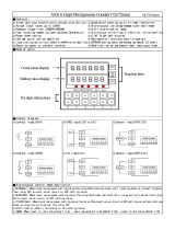
The instrument has two menus accessible to the user :
‘Conguraon menu’ (key ‘SQ’) (<)
‘Fast access’ menu (key ‘UP’) (5)
Conguraon menu
The ‘conguraon menu’ modies the conguraon
parameters to adapt the instrument to the applicaon
needs. To access the ‘conguraon menu’ press for 1
second the ‘SQ’ (<) key. This access can be blocked by
acvang the ‘Password’ (‘PASS’) funcon. While operang the
‘conguraon menu’, the alarm status is ‘hold’ to the
status it had before accessing the menu, and the output and
control modules remain in ‘error’ state. When leaving the
‘conguraon menu’, the instrument applies a system
reset, followed by a brief disconnecon of the alarms and the
output and control modules. Funconality is then recovered.
For a detailed explanaon on the ‘conguraon menu’
see the following secons, and for a full view of the
‘conguraon menu’ see secon 1.22.
‘Fast access’ menu
The ‘fast access’ menu is an operator congurable menu,
providing fast and direct access to the most usual funcons
of the instrument with a single key pad stroke. Press key ‘UP’
(5) to access this menu.
See secon 1.21.11 for a list of selectable funcons for the
‘fast access’ menu in this instrument. The ‘Password’ (‘PASS’)
funcon does not block access to this menu. Accessing and
modifying parameters in the ‘fast access’ menu does not
interfere with the normal funconality of the instrument,
and it does not generate any system reset when validang
the changes.
Operang with the front keypad inside the menus
Key ‘SQ’ (<) - press the ‘SQ’ (<) key for 1 second to
access the ‘conguraon menu’. Inside the menu, the
‘SQ’ (<) key acts as an ‘ENTER’. It enters into the menu opon
selected, and when entering a numerical value, it validates the
number.
Key ‘UP’ (5) - press the ‘UP’ (5) key to access the ‘fast
access’ menu. Inside the menu,the ‘UP’ (5) key sequen-
ally moves through the available parameters and menu en-
tries. When entering a numerical value, it modies the digit
selected by increasing its value to 0, 1, 2, 3, 4, 5, 6, 7, 8, 9.
1.21 Conguraon
1.21.1 How to operate the menus
Key ‘LE’ (3) - press the ‘LE’ (3) key to acvate the
congured special funcons associated to this key. Inside
the menu, the ‘LE’ (5) acts as an ‘ESCAPE’. It leaves the
selected menu level and eventually, by leaving all menu
levels, it leaves from the conguraon menu. Then changes
are applied and the instrument is back to normal funcon.
When entering a numerical value, it selects the acve digit,
and the value is then modied by key ‘UP’ (5).
‘Rollback’
Aer 30 seconds without interacon from the operator, the
instrument will rollback and leave the ‘conguraon menu’
or the ‘fast access’ menu. All changes will be discarded.
Instruments with 4 and 6 digits
The conguraon menus included in this document show
values for a 6 digit instrument. In case of 4 digit instruments,
note that maximum reading values should be 9999 instead
of 999999 to 9999 and minimum reading values should be
-1999 instead of -199999.
(2)
(3)
(3)
(3)
(3)
(3)
(4)
(4)
(4)
(4)
(5)
(5)
(5)
(5)
(3)
(3)
(6)
(6)
(1)
Example of operaon inside
the ‘conguraon menu’.
1. The (<) key enters into the
‘conguraon menu’.
2. The (<) key enters into the
‘InP’ menu.
3. The (5) key moves through
the menu opons.
4. The (<) key selects the
desired range and returns
to the ‘InP’ menu.
5. The (3) key leaves the
actual menu level and
moves to the previous
menu level.
6. The (3) key leaves the
‘conguraon menu’.
Changes are applied and
saved at this moment.
Figure 5 - Example of operaon inside the ‘conguraon menu’

17
1.21.2 Inial set-up
To congure the inial set up of the instrument, select the
working mode and congure the bus parameters.
The instrument has 2 working modes named ‘Full slave’ and
‘Process slave’. In both modes, the reading value is received
from the communicaons bus. The dierences between
modes are related to how the alarms are controlled.
At the ‘Working mode’ (‘ModE’) parameter, select one of the
working modes.
• select ‘Full slave’ to control the alarms directly from
the communicaons bus, by wring to the internal
instrument registers. Analog outputs and other
output and control modules are controlled locally from the
instrument.
• select ‘Process slave’ to control the alarms locally from
the instrument, by manually conguring the setpoint
and other alarm parameters. Analog outputs and other
output and control modules are controlled locally from the
instrument.
Conguraon menus for both modes are slightly dierent.
The following secons will menon when a parameter applies
only to one of the modes.
Press ‘SQ’ (<) for 1 second to access the ‘conguraon
menu’. For a descripon on how to operate inside the menus
see secon 1.21.1. For a full vision of the ‘conguraon menu’
structure see secon 1.22.
Working mode
‘Process slave’ mode
‘Full slave’ mode
Speed
(kbps)
from 38.4 Kbps
...
...
to 600 bps
Bus
conguraon
8 bits, no parity, 1 stop
Format
8 bits, even parity, 1 stop
8 bits, odd
parity
, 1
stop
8 bits, no parity, 2 stop
At the ‘Bus conguraon’ (‘buS’) menu congure the bus
speed and the bus data format.
• at the ‘Speed’ (‘bAud’) parameter select the bus speed,
in kbps.
• at the ‘Format’ (‘bItS’) parameter select the bus format
between ‘8n1’, 8e1’, ‘8o1’ and ‘8n2’.

18
As a standard, Modbus RTU protocol is designed to work with
registers of 16 bits. This allows to work with numerical values
between 32767 and -32767. In order to work with numerical
values up to 999999 and -199999, larger register of 32 bits
are needed (see secon 1.21.5). A 32 bits register is read and
wrien as if it was composed of 2 registers of 16 bits.
To write on 32 bits registers use funcon 16 ‘Write mul
-
ple registers’ and to read on 32 bits registers use funcon
3 ‘Read registers’. Working with 32 bits registers has the
following limitaons:
• registers of 32 bits (2 registers of 16 bits) must be
wrien or read using the same single funcon. It is not
allowed to write 16 bits with a funcon and then write
the following 16 bits in the next funcon.
• in case of wring (or reading) only a part of a 32 bits
register (only rst 16 bits or last 16 bits) the instrument
will discard the write (or read) funcon. Instrument will
not transmit error code.
Available ‘funcons’, ‘registers’ and ‘coils’ for each mode are
explained at secons 1.17, 1.18, 1.19 and 1.20.
In ‘Full slave’ mode, the ‘master’ controls the acvaon
and deacvaon of each individual alarm in the ‘slave’
instrument, by sending write funcons to the appropriate
registers or coils. By default, alarm control is performed
by wring to coils. To switch to alarm control by wring to
registers, congure the menu ‘Alarm control’ (‘AL.ct’).
Alarm control by coil or register is selectable but only one
type of control can be acve.
Available ‘funcons’, ‘registers’ and ‘coils’ for each mode are
explained at secons 1.17, 1.18, 1.19 and 1.20.
The ‘watchdog’ funcon acvates an error state in case of
loss of communicaon with the ‘master’. To congure the
‘watchdog’ indicate the maximum me accepted to wait
between two frames received. If the congured me is
exceeded, the instrument acvated the ‘watchdog error’.
When a correct frame is received, the ‘watchdog’ mer is
reset.
Frames that can reset the ‘watchdog’ mer are those
addressed to the ‘slave’ instrument. These frames must
conform to the Modbus RTU protocol and have a correct
CRC.
If the funcon or register or coil indicated in the frame is
not correct, the ‘slave’ instrument will sll reset the ‘watch
-
dog’ mer. It will also reply with the corresponding error
message.
The internal alarms of the instrument can be associated
to the ‘watchdog’. In case of ‘watchdog’ acvaon, the
associated alarm will also acvate (see secon 1.21.8).
Display can also be congured to show an error message in
case of ‘watchdog’ error. It can be congured for ashing,
dash (‘------’) or to show message ‘Err.W’.
The instrument can be assigned any address between
1 and 247.
1.21.3 Addresses
1.21.4 ‘Watchdog’ funcon
1.21.5 16 bits or 32 bits registers
1.21.6 Alarm control : registers and ‘coils’

19
At the ‘Conguraon’ (‘cnF’) menu, congure the
parameters associated to the instrument funcon, such as
the local address, the ‘watchdog’ me and error behavior,
the data length and the alarm control.
• at the ‘Local address’ (‘Addr’) parameter congure the
local address of the instrument. Values from 1 to 247.
• at the ‘Watchdog’ (‘W.doG’) parameter congure the
maximum waing me between frames, in seconds.
Select ‘0’ to disable the ‘watchdog’. Maximum value
120 seconds. In case of watchdog error acvaon, the
funcon ‘on.Er’ will be triggered (see secon 1.21.4).
• at the ‘On error’ (‘on.Er’) parameter congure the acon
in case of watchdog error:
- select ‘Flash’ (‘FLSh’) to acvate the ash on display
- select ‘Dashes’ (‘dASh’) to acvate dashes (‘----’) on
display
- select ‘Watchdog error’ (‘Err.W’) to acvate the
message ‘Err.W’ on display.
- select ‘do nothing’ (‘nonE’) to perform no acon.
• at the ‘Data lengh’ (‘dAtA’) parameter congure the
instrument to work with 16 bit or 32 bit registers. By
default, it works with 16 bit registers (see secon 1.21.5).
• the ‘Alarm control’ (‘AL.ct’) parameter applies only
in ‘Full Slave’ mode. Select ‘coIL’ or ‘hoLd’ to cong
-
ure alarm control by wring to coils or to registers (see
secon 1.21.6).
Conguraon
1 to 247
Local address
Watchdog
Waing me
On error
Flash
Dashes (----)
Do nothing
Watchdog error
Data length
16 bits
32 bits
Alarm control
By registers
By ‘coils’
1.21.7 Conguraon menu
/