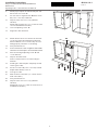
V-ZUG 61013 is a versatile range hood that offers both extracted air and recirculation air operating modes, making it suitable for a variety of kitchen layouts. It features a sleek built-in design that seamlessly integrates into your cabinetry, providing efficient odor and grease removal while cooking.
V-ZUG 61013 is a versatile range hood that offers both extracted air and recirculation air operating modes, making it suitable for a variety of kitchen layouts. It features a sleek built-in design that seamlessly integrates into your cabinetry, providing efficient odor and grease removal while cooking.


-
 1
1
-
 2
2
-
 3
3
-
 4
4
-
 5
5


V-ZUG 61013 Installation guide
- Category
- Cookers
- Type
- Installation guide
V-ZUG 61013 is a versatile range hood that offers both extracted air and recirculation air operating modes, making it suitable for a variety of kitchen layouts. It features a sleek built-in design that seamlessly integrates into your cabinetry, providing efficient odor and grease removal while cooking.
Ask a question and I''ll find the answer in the document
Finding information in a document is now easier with AI
Related papers
-
V-ZUG DFPQ9 Installation guide
-
V-ZUG 62001 Installation guide
-
-
-
-
-
-
V-ZUG 393 Installation guide
-
-
V-ZUG 64004 Installation guide