Westinghouse WGen7500 User manual

Category
Power generators
Type
User manual
USER MANUAL
WGen7500
Portable Generator
7500 Running Watts | 9500 Peak Watts
REMOTE START
PUSH BUTTON
ELECTRIC START
2 | Westinghouse Portable Power
DISCLAIMERS:
All information, illustrations and specications in this manual are based on the latest information available at
the time of publishing. The illustrations used in this manual are intended as representative reference views only.
Moreover, because of our continuous product improvement policy, we may modify information, illustrations and/or
specications to explain and/or exemplify a product, service or maintenance improvement. We reserve the right
to make any change at any time without notice. Some images may vary depending upon which model is shown.
ALL RIGHTS RESERVED:
No part of this publication may be reproduced or used in any form by any means – graphic, electronic or
mechanical, including photocopying, recording, taping or information storage and retrieval systems – without the
written permission of MWE Investments LLC.
DANGER
This manual contains important instructions for operating this generator. For your safety
and the safety of others, be sure to read this manual thoroughly before operating the
generator. Failure to properly follow all instructions and precautions can cause you and
others to be seriously hurt or killed.
California
Proposition 65 Warning
The engine exhaust from this product
contains chemicals known to the state
of California to cause cancer, birth
defects or other reproductive harm.
California
Proposition 65 Warning
Certain components in this product and its
related accessories contain chemicals
known to the state of California to cause
cancer, birth defects or other reproductive
harm. Wash hands after handling.
Model
Number
Running
Watts
Peak
Watts
Fuel
Tank
Size
(L/G)
Rated
Speed
(RPM)
Ignition
Type
Spark
plug
Engine
Disp (cc)
Stroke X
Bore
Oil
Capacity
(L) Oil Type THD
WGen7500 7500 9500 25/6.6 3600 TCI F7TC 420 66X90 1.10 10W30 <23%
NOTICE
Even with a carburetor modication, engine horsepower will decrease about 3.5% for each 300 meter (1,000 foot) increase in altitude.
The eect of altitude on horsepower will be greater if no carburetor modication is made. A decrease in engine horsepower will de-
crease the power output of the generator.
WGen TECHNICAL SPECIFICATIONS
HAVE QUESTIONS?
Email us at service@wpowereq.com
or call 1-855-944-3571
Westinghouse Portable Power | 3
FOR YOUR RECORDS:
Date of Purchase:
Generator Model Number:
Purchased from Store/Dealer:
Generator Serial Number:
IMPORTANT: KEEP YOUR PURCHASE RECEIPT TO ENSURE TROUBLE-FREE WARRANTY
COVERAGE.
PRODUCT REGISTRATION
To ensure trouble-free warranty coverage, it is important you register your Westinghouse generator.
You can register your generator by either:
1. Filling in the product registration form below and mailing to:
Product Registration
MWE Investments LLC
777 Manor Park Drive
Columbus, Ohio 43228
2. Registering your product Online at www.westinghouseportablepower.com/register-your-product/
To register your generator you will need to locate the following information:
WESTINGHOUSE PRODUCT REGISTRATION FORM
PERSONAL INFORMATION GENERATOR INFORMATION
First Name: _______________________________________ Model Number: _____________________________________
Last Name: _______________________________________ Serial Number: ______________________________________
Street Address: ___________________________________ Date Purchased: ____________________________________
Street Address: ___________________________________ Purchased From: ____________________________________
City, State, ZIP: ____________________________________
Country: __________________________________________
Phone Number: ___________________________________
E-Mail: ___________________________________________
60x20mm
( 65x20mm)
Made in China/ Fabriqu é en Chine
CSA Master Contract
Number :
Numéro de contrat
principa l de CS A
MWE Investments LLC
Columbus Ohio 43228 USA
Con u à columbus , Ohio,tats-Unis
MWE Investments LLC
Columbus Ohio 43228 Etats-Unis
Par t N0.
Numéro de
pièc e
Designed in Columbus , Ohio USA
268850
268850
4 | Westinghouse Portable Power
TABLE OF CONTENTS
WGEN7500 TECHNICAL SPECIFICATIONS ........2
PRODUCT REGISTRATION .....................3
For Your Records: ..........................3
Product Registration .......................3
Product Registration Form ...................3
SAFETY .....................................5
Safety Denitions ..........................5
Safety Symbol Denitions ...................5
General Safety Rules ........................6
Safety Labels and Decals ....................7
UNPACKING .................................9
What Comes in the Box ......................9
Wheel Kit Accessories Box ...................9
ASSEMBLY .................................10
Installing Wheels and Feet ....................10
Installing the Battery ........................11
FEATURES .................................12
Generator Features .........................12
Control Panel Features .....................14
OPERATION .................................15
Before Starting the Generator .................15
Power Cord ..............................16
Using Extension Cords ...................16
Using Westinghouse Power Cord ...........16
Transfer Switch Connections ..................17
Engine Fluids and Fuel .......................18
Adding Gasoline to the Fuel Tank ...........18
Starting the Generator ......................19
Manually Starting the Generator ............19
Remote Starting the Generator .............19
Push Button Start .......................20
Stopping the Generator ......................21
Normal Operation .......................21
During an Emergency ....................21
MAINTENANCE ..............................22
Maintenance Schedule ......................22
Engine Oil Maintenance .....................23
Engine Oil Specication ...................23
Checking Engine Oil .....................23
Adding Engine Oil .......................23
Changing Engine Oil .....................24
Air Filter Maintenance .......................24
Cleaning the Air Filter ....................24
Spark Plug Maintenance .....................25
Checking and Adjusting Valve Lash ..............26
Testing GFCI Outlets ........................26
Battery Service. . . . . . . . . . . . . . . . . . . . . . . . . . . . . 26
Battery Charger ..........................26
Battery Replacement .....................27
Cleaning the Generator ......................27
Storage ..................................27
TROUBLE SHOOTING .........................28
EXPLODED AND ENGINE VIEWS ................30
WGen7500 Exploded View ...................30
WGen7500 Engine View .....................31
SCHEMATICS ................................32
WGen7500 Schematic .......................32
Westinghouse Portable Power | 5
SAFETY DEFINITIONS
The words DANGER, WARNING, CAUTION and
NOTICE are used throughout this manual to highlight
important information. Be certain that the meanings of
these alerts are known to all who work on or near the
equipment.
This safety alert symbol appears
with most safety statements. It
means attention, become alert, your
safety is involved! Please read and
abide by the message that follows
the safety alerts symbol.
DANGER
Indicates a hazardous situation which, if not
avoided, will result in death or serious injury.
WARNING
Indicates a hazardous situation which, if not
avoided, could result in death or serious injury.
CAUTION
Indicates a hazardous situation which, if not
avoided, could result in minor or moderate injury.
NOTICE
Indicates a situation which can cause damage
to the generator, personal property and/or the
environment, or cause the equipment to operate
improperly.
NOTE: Indicates a procedure, practice or condition
that should be followed in order for the
generator to function in the manner
intended.
SAFETY
SAFETY SYMBOL DEFINITIONS
6 | Westinghouse Portable Power
DANGER
Never use the generator in a location that is wet or damp. Never expose the generator to rain,
snow, water spray or standing water while in use. Protect the generator from all hazardous weather
conditions. Moisture or ice can cause a short circuit or other malfunction in the electrical circuit.
Never operate the generator in an enclosed area. Engine exhaust contains carbon monoxide. Only
operate the generator outside and away from windows, doors and vents.
WARNING
Voltage produced by the generator could result in death or serious injury.
Never operate the generator in rain or a ood plain unless proper precautions are taken to avoid
being subject to rain or a ood.
Never use worn or damaged extension cords.
Always have a licensed electrician connect the generator to the utility circuit.
Never touch an operating generator if the generator is wet or if you have wet hands.
Never operate the generator in highly conductive areas such as around metal decking or steel
works.
Always use grounded extension cords. Always use three-wire or double-insulated power tools.
Never touch live terminals or bare wires while the generator is operating.
Be sure the generator is properly grounded before operating.
WARNING
Gasoline and gasoline vapors are extremely ammable and explosive under certain conditions.
Always refuel the generator outdoors, in a well-ventilated area.
Never remove the fuel cap with the engine running.
Never refuel the generator while the engine is running. Always turn engine o and allow the
generator to cool before refueling.
Only ll fuel tank with gasoline.
Keep sparks, open ames or other form of ignition (such as match, cigarette, static electric
source)away when refueling.
Never overll the fuel tank. Leave room for fuel to expand. Overlling the fuel tank can result in a
sudden overow of gasoline and result in spilled gasoline coming in contact with HOT surfaces.
Spilled fuel can ignite. If fuel is spilled on the generator, wipe up any spills immediately. Dispose
of rag properly. Allow area of spilled fuel to dry before operating the generator.
Wear eye protection while refueling.
Never use gasoline as a cleaning agent.
Store any containers containing gasoline in a well-ventilated area, away from any combustibles or
source of ignition.
Check for fuel leaks after refueling. Never operate the engine if a fuel leak is discovered.
WARNING
Never operate the generator if powered items overheat,
electrical output drops, there is sparking, ames or smoke
coming from the generator, or if the receptacles are
damaged.
Never use the generator to power medical support
equipment.
Always remove any tools or other service equipment used
during maintenance from the generator before operating.
NOTICE
Never modify the generator.
Never operate the generator if it
vibrates at high levels, if engine
speed changes greatly or if the
engine misres often.
Always disconnect tools or
appliances from the
generator before starting.
GENERAL SAFETY RULES
SAFETY
Westinghouse Portable Power | 7
SAFETY
SAFETY LABELS AND DECALS
4
5
1
1
3
3
4
2
Made in China/
Fabriqu é en Chine
CSA Master Contract
Number :
Numéro de contrat
principa l de CSA
MWE Investments LLC
Columbus Ohio 43228 USA
Con u à columbus , Ohio,tats-Unis
MWE Investments LLC
Columbus Ohio 43228 Etats-Unis
Par t N0.
Numéro de
pièc e
Designed in Columbus , Ohio USA
4
2 5
5
8 | Westinghouse Portable Power
SAFETY
SAFETY LABELS AND DECALS
8
9
7
10
8
9
6
6
7
5
10
Westinghouse Portable Power | 9
1. Washer (2 used)
2. Flange Bolt M8 x16mm (4 used)
3. Hairpin Cotter Pin (2 used)
4. Wheel Axle Pin (2)
CAUTION
Always have assistance when lifting
the generator. The generator is heavy;
lifting it could cause bodily harm.
Avoid cutting on or near staples
to prevent personal injury.
Tools required – box cutter or similar device.
1. Carefully cut the packing tape on top of the carton.
2. Fold back top aps to reveal the manual.
3. Remove the Wheel Kit Accessories cardboard box.
4. Carefully cut two sides of the carton to
remove the generator.
WHAT COMES IN THE BOX
Manual
Quick Start Guide/Maintenance Schedule
Wireless Remote Starter (1)
1.1 Liter Bottle of SAE 10W30 Oil (1)
Spark Plug Socket Wrench (1)
Wheel Kit Accessories Box
Battery Charger (1)
Funnel (1)
WHEEL KIT ACCESSORIES BOX
Open the Wheel Kit Accessories box and verify the
contents against the list right. If any parts are missing,
please locate an authorized Westinghouse Generator
dealer at [email protected] or call
1-855-944-3571.
UNPACKING
Figure 1 -Wheel and Feet Kit Hardware
1
2
3
4
10 | Westinghouse Portable Power
INSTALLING WHEELS AND FEET
BEFORE ASSEMBLING THE
GENERATOR, REVIEW THE SAFETY
SECTION STARTING ON PAGE 5.
CAUTION
Never lift the generator without
assistance. The generator is heavy
and lifting without assistance could
result in personal injury.
Never use the handles as a lifting point
to support the entire weight of the
generator. Only use the handles to move
the generator by lifting the handles and
using the wheels to move the generator.
Use caution when collapsing the
handles. Hands and ngers could get
caught and pinched.
NOTICE
Assembling the generator will require lifting the unit
on one side. Make sure all engine oil and fuel are
drained from the unit prior to assembling. Once
assembled, the wheel kit is not intended for on-
road use. The wheel kit is designed for use on this
generator only.
INSTALLING FEET TO FRAME
1. Place generator on a at surface.
2. Place a piece of cardboard or other soft material to
tip the generator onto, to protect the frame paint
and prevent the generator from sliding. Tip the
generator onto the side.
3. Install the mounting foot to the frame using M8
ange bolts.
1 - Mounting Feet
2 - Flange Bolts M8
INSTALLING WHEELS TO FRAME
1. Insert axle pin through washer and wheel.
2. Install the wheel with axle pin through the axle
bracket on the frame. The eye of the bolt should be
facing toward the inside of the generator.
2
1
3
Figure 3 - Assemble Wheel to Frame
3. Install the hairpin cotter through the axle pin to lock
it in place.
1 - Axle Bracket
2 - Hairpin Clip
3 - Axle Pin
4. Repeat previous steps on other wheel.
ASSEMBLY
Figure 2 -Wheel Assembly
Figure 1 - Assemble Mounting Feet to Frame
Westinghouse Portable Power | 11
4. Pull back the black boot and securely attach
the negative (-) battery cable (black boot) to the
negative (-) battery post as shown in Figure 5.
Replace the black boot so it protects the cable lug
and battery post.
1 - Positive (+) Battery Cable (Red)
2- Negative (-) Battery Cable (Black)
NOTE: The electric start generator is equipped
with a battery charging feature. Once the engine is
running, a small charge is supplied to the battery
via the battery cables and will slowly recharge the
battery.
INSTALLING THE BATTERY
WARNING
To avoid electrics hock:
ALWAYS connect the positive (+)
battery cable (red boot) rst when
connecting battery cables.
ALWAYS disconnect the negative (-)
battery cable (black boot) rst when
disconnecting battery cables.
NEVER connect the negative (-)
battery cable (black boot) to the
positive (+) post on the battery.
NEVER connect the positive (+)
battery cable (red boot) to the
negative (-) post on the battery.
NEVER touch both battery posts
simultaneously.
NEVER place a metal tool across
both battery posts.
ALWAYS use insulated or
nonconducting tools when installing
the battery.
NOTE: THE GENERATOR COMES EQUIPPED WITH
THE POSITIVE BATTERY CABLE (RED BOOT)
ALREADY ATTACHED.
1. Verify the positive (+) battery cable (red boot) is
securely tightened to the positive (+) battery post.
Make sure boot is over battery post.
2. Carefully remove the protective wrapping around
the lug of the negative (-) battery cable (black boot).
3. Locate negative (-) cable attached to alternator
cable, remove tie and route to the negative (-)
battery post. See gure 4 below for location of
negative (-) cable.
ASSEMBLY
Figure 4 - (1) Negative Cable
Figure 5 - Attaching the Negative (-) Battery Wire (black)
1
1
2
12 | Westinghouse Portable Power
Push Button Electric Start: Starts and stops
the engine.
Engine Control Switch/Battery Disconnect:
Allows fuel to ow to engine and energizes
the ignition system. Also, disconnects battery
power when in “Stop” position.
Fuel Cap: Close until clicking sound is heard.
Control Panel: Contains the circuit breakers
and outlets.
Battery: Included for electric start models.
Oil Fill Plug/Dipstick: Must be removed to add
and check oil.
Oil Drain Plug: Must be removed to drain
engine oil
FEATURES
Never Flat Wheels: For easy portability
Fuel Shut o Valve: Controls the ow of fuel
to the engine.
Auto Choke: Battery must be hooked up for auto
choke to work properly.
Single Piece Handle: Includes rubber grip. Allows
you to easily push or pull unit with one hand.
2
1
1
5
6
7
8
10
9
11
2
3
4
3
4
5
7
6
11
9
10
8
Westinghouse Portable Power | 13
Fuel Gauge: Indicates fuel level.
Spark Plug Boot (Wire): Must be removed
when servicing the engine or the spark plug.
CARB Canister: Required for models sold into
and used in California.
Muer and Spark Arrester: Avoid contact
until engine is cooled down. Spark arrestor
prevents sparks from exiting the muer. It must
be removed for servicing.
FEATURES
1
2
3
4
1
2
3
4
14 | Westinghouse Portable Power
WGen7500
7500 Running Watts | 9500 Peak Watts
SMARTŁ
SWITCHŁ
READY
20-Amp Circuit Breakers: Each circuit breaker
limits the current that can be delivered through
the 120-volt duplex outlets to 20amps.
Battery Charge Port: Used in conjunction with
the ST Switch when the generator is in standby
mode to charge the battery (battery charger
included).
Battery Indicator Light: When light is illuminated,
the battery is connected and providing power to
the electronics.
Smart Switch Outlet: Connects the Smart
Switch (sold separately) to the control panel.
Ground Terminal: The ground terminal is used to
ground the generator.
Push Start Button:
Push once to automatically start the engine.
Green light shows when unit is on.
Push again to stop the engine.
Engine Control Switch/Battery Disconnect:
Switch to “Stop” to stop the engine. When in
“Stop” position it prevents the unit from drawing
power from the battery. Switch to “Run” before
starting engine.
Data Center: Displays how many hours the
generator has been run when under load.
Main Circuit Breaker: The main circuit breaker
controls total output of all outlets to protect the
generator.
120/240-Volt, 30-Amp Twist Lock Outlet
(NEMA L14-30R): Outlet can supply either
120V or 240V output.
120-Volt, 20-Amp Duplex GFCI Outlets
(NEMA 5-20R): Each outlet is capable of carrying
a maximum of 20 amps on a single receptacle or a
combination of both receptacles.
CONTROL PANEL FEATURES
1
8
9
10
11
2
3
4
5
6
7
3 4 5 6 721
10 1198
FEATURES
Westinghouse Portable Power | 15
WeatherNever operate your generator outdoors during
rain, snow or any combination of weather conditions that
could lead to moisture collecting on, in or around the
generator.
Dry SurfaceAlways operate the generator on a dry
surface free of any moisture.
No Connected LoadsMake sure the generator has no
connected loads before starting it. To ensure there are no
connected loads, unplug any electrical extension cords
that are plugged into the control panel receptacles.
NOTICE
Starting the generator with loads already applied
to it could result in damage to any appliance being
powered o the generator during the brief start-up
period.
Grounding the Generator – The National Electric Code
(NEC), as well as many local electrical codes, may require
the generator to be connected to earth ground. The
most common application that requires a ground rod is
when you are using the generator as a separately derived
system to provide back up power to your house. Typically
this is when a transfer switch has a switched neutral.
As the generator application has many variables that
cannot be determined by the manufacturer of the
generator, a licensed electrician will need to determine if a
grounding rod is needed.
If a licensed electrician has determine the application
requires a ground rod, make sure it is connected to earth
ground by connecting the ground terminal on the control
panel to earth ground using copper wire (minimum 10
AWG). Consult a qualied electrician for local grounding
requirements.
Neutral Bonded: There is a permanent conduct or
between the generator (stator winding) and the frame.
WARNING
Be sure the generator is properly
connected to earth ground before
operating. The generator must be
grounded to prevent electrical shock
due to faulty appliances.
BEFORE STARTING THE GENERATOR
BEFORE STARTING THE GENERATOR,
REVIEW SAFETY SECTION STARTING
ON PAGE 5.
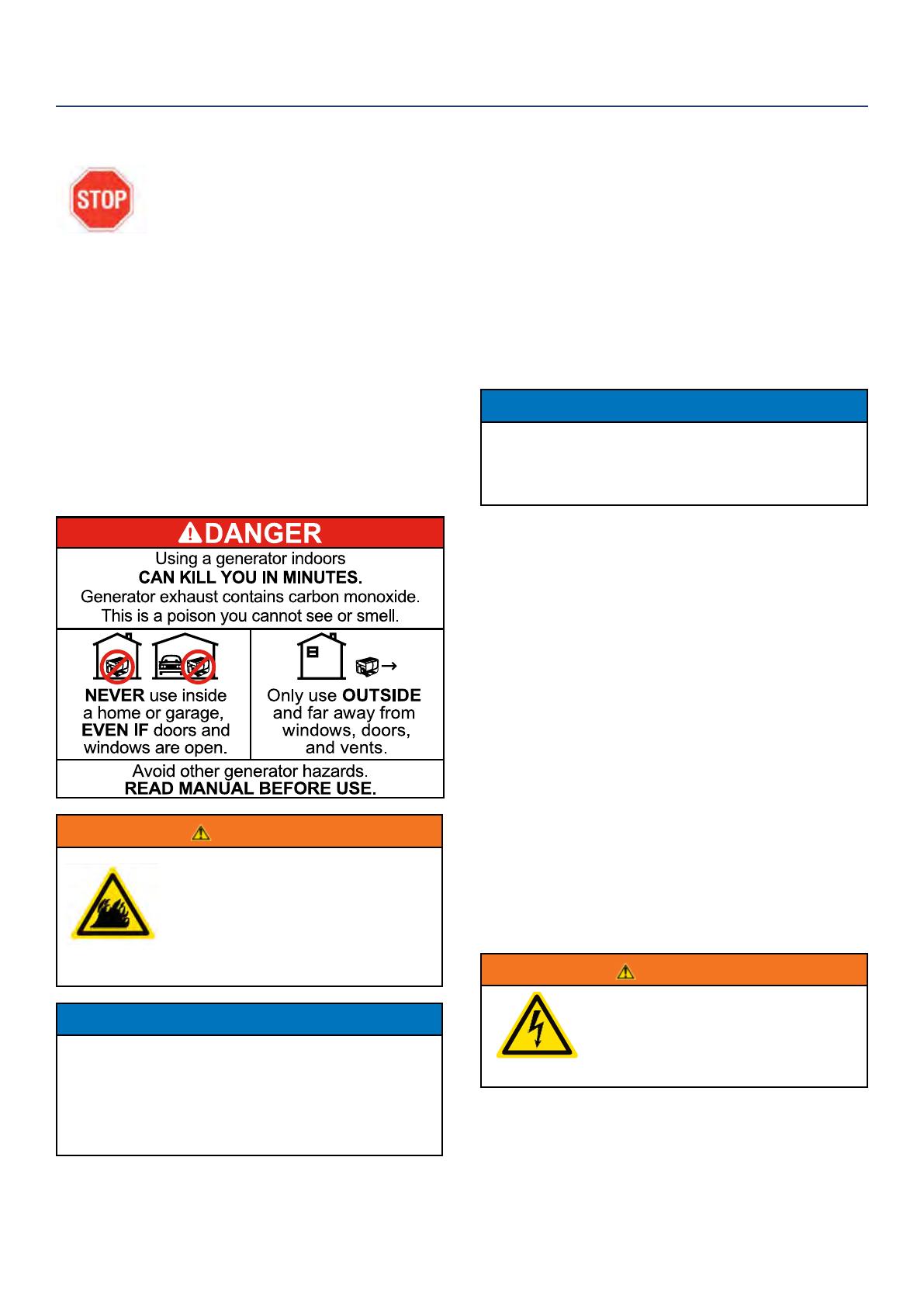
Location Selection – Before starting the generator,
avoid exhaust and location hazards by verifying:
You have selected a location to operate the generator
that is outdoors and well ventilated.
You have selected a location with a level and solid
surface on which to place the generator.
You have selected a location that is at least 6 feet
(1.8 m) away from any building, other equipment or
combustible material.
If the generator is located close to a building, make
sure it is not located near any windows, doors and/
or vents.
WARNING
Always operate the generator on a
level surface. Placing the generator
on non level surfaces can cause the
generator to tip over, causing fuel
and oil to spill. Spilled fuel can ignite
if it comes in contact with an ignition
source such as a very hot surface.
NOTICE
Only operate the generator on a solid, level surface.
Operating the generator on a surface with loose
material such as sand or grass clippings can cause
debris to be ingested by the generator that could:
• Block cooling vents
• Block air intake system
OPERATION
16 | Westinghouse Portable Power
POWERCORD
Using Extension Cords
Westinghouse Portable Power assumes no responsibility for the content within this table. The use of this table is the
responsibility of the user only. This table is intended for reference only. The results produced by using this table are
not guaranteed to be correct or applicable in all situations as the type and construction of cords are highly variable.
Always check with local regulations and a licensed electrician prior to installing or connecting an electrical appliance
Using Westinghouse Power Cord
Use the extension cord chart to determine the size
of the conductor for extension cord applications.
Determine the distance of the generator to the
appliance on the top line of the chart. Then select the
rated amperage of the generator on the left side of the
chart. Where the two meet is the size of the conductor
required for the application.
The WCG25 power cord is connected to the generator
at the 120/240 plug. The opposite end of the power
cord is a fan tail receptacle with 2 green receptacles
and 2 red receptacles. Each receptacle is rated at
120 volts AC. To balance the load on the generator’s
alternator, use the red and green identiers on the fan
tail receptacle. To keep the load balanced, connect
the loads so that both color receptacles are used. An
example is one in red and one in green. Do not connect
2 in red and none in green, or 2 in green and none in
red. If only one color receptacle is used with multiple
loads, the alternator may experience an unbalanced
load, causing undue vibration to generator.
OPERATION
1
2
- WCG25 Extension Cord
Red Dots
Green Dots
Westinghouse Portable Power | 17
ADDING / CHECKING ENGINE
FLUIDS AND FUEL
BEFORE ADDING/CHECKING ENGINE
FLUIDS AND FUEL, REVIEW SAFETY
SECTION STARTING ON PAGE 5.
DANGER
Filling the fuel tank with gasoline while
the generator is running can cause
gasoline to leak and come in contact
with hot surfaces that can ignite the
gasoline.
Before starting the generator, always check the level of:
Engine oil
Gasoline in the fuel tank
Once the generator is started and the engine gets
warm, it is not safe to add gasoline to the fuel tank or
engine oil to the engine while the engine is running or
the engine and muer are hot.
CHECKING AND / OR ADDING ENGINE OIL
WARNING
Internal pressure can build in the
engine crankcase while the engine
is running. Removing the oil ll plug/
dipstick while the engine is hot can
cause extremely hot oil to spray out
of the crankcase and can severely
burn skin. Allow engine oil to cool for
several minutes before removing the
oil ll plug/dipstick.
The unit as shipped does not contain oil in the engine.
You must add engine oil before starting the generator
for the rst time. See Checking Engine Oil and Adding
Engine Oil on page 23 for instructions on checking
engine oil level and the procedure for adding engine oil.
NOTICE
The engine does not contain engine oil as shipped.
Attempting to start the engine can damage
engine components. The owner of the generator
is responsible to ensure the proper oil level is
maintained during the operation of the generator.
Failure to maintain the proper oil level can result in
engine damage.
TRANSFER SWITCH CONNECTIONS
The Westinghouse generator is wired with the neutral
bonded to ground. If you are connecting your generator
to a panel board transfer switch, a licensed electrician
will need to consider removing the bonded neutral to
ensure proper operation of household GFCI circuits.
This is done by removing the jumper wire that connects
the alternator ground to the alternator neutral.
If the bonded neutral is removed the generator must be
relabeled as oating neutral on the control panel.
If your generator is equipped with GFCI receptacles,
removing the bonded neutral may not allow proper
operation of the GFCI receptacles. Keep the jumper
wire with the owner’s manual in case it is needed for
future use when not connected to a transfer switch.
OPERATION
Figure 6
18 | Westinghouse Portable Power
ADDING GASOLINE TO THE FUEL TANK
WARNING
Never refuel the generator while the
engine is running.
Always turn the engine o and allow
the generator to cool before refueling.
Required Gasoline – Only use gasoline that meets the
following requirements:
Unleaded gasoline only
Gasoline with maximum 10% ethanol added
Gasoline with an 87 octane rating or higher
Filling the Fuel Tank – Follow the steps below to ll the
fuel tank:
1. Shut o the generator.
2. Allow the generator to cool down so all surface
areas of the muer and engine are cool to the
touch.
3. Move the generator to a at surface.
4. Clean area around the fuel cap.
5. Remove the fuel cap by rotating counterclockwise.
6. Slowly add gasoline into the fuel tank. Be very
careful not to overll the tank. The gasoline level
should NOT be higher than the ller neck (see
Figure 7).
7. Install the fuel cap by rotating clockwise until
you hear a click, indicating the cap is completely
installed.
CAUTION
Avoid prolonged skin contact with
gasoline. Avoid prolonged breathing of
gasoline vapors.
BEFORE STARTING THE GENERATOR
BEFORE STARTING THE GENERATOR,
REVIEW SAFETY SECTION STARTING
ON PAGE 5.
Before attempting to start the generator,
verify the following:
The engine is lled with engine oil. See Checking
Engine Oil on page 23.
The generator is situated in a proper location
(Location Selection on page 15).
The generator is on a dry surface (Weather and Dry
Surface on page 15).
All loads are disconnected from the generator (No
Connected Loads on page 15).
The generator is properly grounded the Generator
(page 15).
DANGER
Never use the generator in a location
that is wet or damp. Never expose the
generator to rain, snow, water spray or
standing water while in use. Protect
the generator from all hazardous
weather conditions. Moisture or ice
can cause a short circuit or other
malfunction in the electrical circuit.
Never operate the generator in an
enclosed area. Engine exhaust
contains carbon monoxide. Only
operate the generator outside and
away from windows, doors and vents.
NOTICE
The engine is equipped with a low oil shutdown
switch. If the oil level becomes low, the engine may
shut down and not start until the oil is lled to the
proper level. Poor oil quality may interfere with the
operation of the low oil shutdown switch.
The owner of the generator is responsible to ensure
the proper oil level is maintained during the operation
of the generator. Failure to maintain the proper oil
level can result in engine damage.
OPERATION
Figure 7 - Maximum Gasoline Fill Level
Westinghouse Portable Power | 19
MANUALLY STARTING THE GENERATOR
1. Check oil levels (see Adding Engine Oil page 23)
2. Battery must be connected for Auto Choke to work.
3. Make sure the circuit breakers are properly set (see
Figure 8 below).
240/120VMain Circuit Breaker Operating Position
240/120V Main Circuit Breaker Tripped Position
120V Circuit Breaker Operating Position
120V Circuit Breaker Tripped Position
4. Move the fuel shut o valve to the ON position (see
Figure 9 below).
ON
OFF
Figure 9 - Fuel Shut O - ON
5. Push the engine control switch into the RUN
position (see Figure 10 below).
6. Firmly grasp and pull the recoil handle slowly until
you feel increased resistance. At this point, apply
a rapid pull while pulling up and slightly away from
the generator (see Figure 11).
REMOTE STARTING THE GENERATOR
1. Check oil levels (see Adding Engine Oil page 23)
2. Battery must be connected for Auto Choke to work.
3. Make sure the circuit breakers are properly set (see
Figure 8).
4. Move the fuel shut o valve to the ON position (see
Figure 9).
5. Push the engine control switch into the RUN
position (see Figure 10).
6. Push the “Start” icon on the wireless remote. (see
Figure 12 below)
OPERATION
Figure 8 - Breakers
Figure 10 - Engine Control Switch - RUN
Figure 12 - Wireless Remote - START
Figure 11 - Engine Recoil Handle - PULL
1
2
3
4
START
STOP
20 | Westinghouse Portable Power
ONE PUSH START
1. Check oil levels (see Adding Engine Oil page 23)
2. Verify the battery is properly installed and both
battery cables are attached (see Installing the
Battery on page 11).
3. Make sure the circuit breakers are properly set (see
Figure 8 on page 19.
4. Move the fuel shuto valve to the ON position (see
Figure 13 below).
Figure 13 - Fuel Shut O - ON
5. Push the engine control switch into the RUN
position (see Figure 14 below).
Figure 14 - Engine Control Switch - RUN
6. Push and hold the engine start push button for 1
second and release (see Figure 15).
The engine will automatically set the choke and
begin the start sequence.
If the engine has started successfully the light
indicator on the engine start button will turn
green.
If the engine fails to start, the generator controls
will attempt to start the engine two more times
for a total of three attempts.
If the third attempt fails, the light on the engine
start button will turn red.
If the engine has failed to start after three
attempts the engine start button can be pushed
again to begin the automatic start sequence.
The red engine stop button can be pushed at any
time during the automatic start sequence to abort
the engine start attempt.
NOTE: If the cranking speed drops after each
unsuccessful attempt, then the battery may not
be adequately charged. You can alternatively start
the generator using the recoil start as instructed
in Manually Starting a Generator on page 19.
Figure 15 - Push Button Start
OPERATION
ON
OFF
  • Page 1 1
  • Page 2 2
  • Page 3 3
  • Page 4 4
  • Page 5 5
  • Page 6 6
  • Page 7 7
  • Page 8 8
  • Page 9 9
  • Page 10 10
  • Page 11 11
  • Page 12 12
  • Page 13 13
  • Page 14 14
  • Page 15 15
  • Page 16 16
  • Page 17 17
  • Page 18 18
  • Page 19 19
  • Page 20 20
  • Page 21 21
  • Page 22 22
  • Page 23 23
  • Page 24 24
  • Page 25 25
  • Page 26 26
  • Page 27 27
  • Page 28 28
  • Page 29 29
  • Page 30 30
  • Page 31 31
  • Page 32 32
  • Page 33 33
  • Page 34 34
  • Page 35 35
  • Page 36 36

Westinghouse WGen7500 User manual

Category
Power generators
Type
User manual

Ask a question and I''ll find the answer in the document

Finding information in a document is now easier with AI