Page is loading ...

A
i
r
F
i
c
i
e
n
c
y
AFAF
The retailer warrants the fan motor to be free from defects in workmanship and material present at time of shipment from the factory for a lifetime after the date of
purchase by the original purchaser. The retailer also warrants all other fan parts to be free from defects in workmanship and material at the time of shipment from the
factory for a period of one year after the date of purchase by the original purchaser. We agree to correct such defects without charge or at our option, replace with a
comparable or superior model if the product is returned to the retailer. To obtain warranty service, you must present a copy of the receipt as proof of purchase. All costs
of removing and reinstalling the product are your responsibility. Damage to any part such as by accident or misuse or improper installation or affixing any accessories, is
not covered by this warranty. A certain amount of “wobble” is normal and should not be considered a defect. Service performed by unauthorized persons shall render the
warranty invalid. There is no other express warranty. This warranty does not apply to any damage that is the result of rust or corrosion. The retailer hereby disclaims any
and all warranties, including but not limited to, those of merchantability and fitness for a particular purpose to the extent permitted by law. The duration of any implied
warranty which cannot be disclaimed is limited to the time period as specified in the express warranty. Some states do not allow limitation on how long an implied
warranty lasts, so the above limitation may not apply to you. The retailer shall not be liable for the incidental, consequential, or special damages arising out of or in
connection with product use or performance except as may otherwise be accorded by law. Some states do not allow the exclusion of incidental or consequential damages,
so the above exclusion or limitation may not apply to you. This warranty gives specific legal rights, and supersedes all prior warranties. Shipping costs for any return of
product as part of a claim on the warranty must be paid by the customer.
Warranty
Important Safety Instructions
Read and Save These Instructions
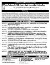
AirFiciency CF60A UL507 Listed Ceiling Fan
Read instructions carefully before assembling or installing your fan.
It is important that you observe all safety information
to help prevent personal injury and/or property damage.
ISV168-14B
• Installation work and electrical wiring should be done by qualified persons only in accordance with all
applicable codes and standards.
• Unplug or disconnect the fan before servicing.
• Use this fan only in the manner intended by the manufacturer. This fan is intended for permanent installation
and to be used for air circulation only.
• The secondary support cable included with the fan must be properly connected.
• The fan shall be supported directly from the building structure. Caution: To reduce risk of injury, use only the
enclosed hardware as the primary means of support.
• Warning: To reduce the risk of personal injury, do not bend the blade brackets when installing the brackets,
balancing the blades, or cleaning the fan. Do not insert foreign objects in between rotating fan blades.
• Ceiling fans without guards are to be installed at least ten feet above the floor with adequate clearance
between blades and adjacent walls, furnishing, etc.
• When mounted in a cathedral ceiling, blade tips should be at least one foot from the angled roof line or air
turbulence may cause fan to sway.
• The supporting beam must be capable of holding at least 80 pounds (or the weight of the fan plus any
accessories that might be added).
• Ceiling fans installed with ceiling fan guards must be installed with J-hook mounting bolt hardware provided,
and must be attached directly to the building structure.
• Do not operate any fan with a damaged cord or plug. Discard fan or return fan to an authorized service facility
for examination and/or repair.
• All set screws must be checked and retightened where necessary after installation but before startup.
Electrical Hookup
• All electrical hookups should be made by a qualified person.
• Check that power source conforms to electrical requirements of fan.
• Disconnect power at main service panel. Lock and tag it to prevent unexpected power application.
• Check state and local codes to assure proper hookup.
• The installation shall be in accordance with the National Electrical Code, ANSI/NFPA 70, and local codes.
• Outlet for unit MUST be a GFCI protected receptacle.
Remove set screw on bottom bell and slide
bottom bell and rubber gaskets up to
expose directional switch.
Slide directional switch to change motor
direction.
Slide gaskets and bottom bell back down to
original position, align set screw holes and
secure with set screw.
WARNING: If bottom bell and gaskets are
not placed properly unit will not be
protected from water infiltration.
bottom bell
set screw
Reversing Fan Direction
directional switch

• Phillips head screwdriver
• Adjustable crescent wrench
• Grounded metal outlet box with single GFCI protected receptacle
• Drill and drill bits
• Carefully remove fan and parts from carton and check for shipping damage
• Check parts list against carton contents
(1) Pre-assembled fan without blades
(3) Blades with brackets attached
(6) Each – bolts, flat washers and rubber washers
(attached to motor housing)
(1) J-hook mounting bolt
(2) Each – lock washers, flat washers and nuts
(1) J-hook secondary support bolt
(2) Cable locks
Loosen set screw on top bell and
slide top bell down to expose top
of down rod.
Inspect the hanging and installation components to ensure that there
is no shipping damage.
Check that power cord is
free from cuts or abrasions.
Check that support bracket
and rubber grommet are secure.
Check that BOTH cable locks
on safety cable are tight.
J-hook
secondary
bolt
nut
flat washer
lock washer
joist
flat washer
lock washer
nut
J-hook
mounting
bolt
Using a drill and drill bit, drill a hole thru joist.
Insert J-hook mounting bolt with assembled
hardware into hole and secure with flat
washer, lock washer and nut as shown below.
Fully secure J-hook mounting bolt to joist by
snugging top and bottom nut.
1½” from installed J-hook mounting
bolt, drill a small pilot hole for
mounting the J-hook secondary bolt.
Using pilot hole as your guide, install
J-hook secondary bolt for secure
installation ensuring all bolt threads
are fully engaged.
Assemble nut, lock
washer and flat
washer onto the
J-hook mounting
bolt as shown below.
(do not replace J-hook
mounting bolt with a
lag bolt.)
Once top of unit has
passed the safety
inspection, install unit.
Insert rubber grommet
into the cradle of the
J-hook mount bolt until
fully seated and insert
loop of safety cable into
J-hook secondary bolt
as shown.
Slide top bell up to cover
both J-hooks, leaving an
1/8” gap between top of
bell and hanging surface
and secure in place by
tightening set screw.
(The 1/8”gap is required
to ensure that down rod is
allowed to hang properly
and not be forced off center
causing fan to wobble or
vibrate.)
Hardware for installing fan blades
is located on the fan base.
Remove bolt, flat washer
and rubber washer from base.
Leave fiber pad in place.
Before installing fan blades, decide which direction
of airflow you intend to utilize the most and install
blades accordingly.
For safety and warranty reasons, ALL FAN BLADES
MUST BE INSTALLED FACING THE SAME DIRECTION.
For downward air flow
For upward air flow
fiber
pad
bolt
flat
washer
rubber
washer
Align fan blade mounting holes
with holes in base and secure with
hardware as shown.
Using only hand tools, tighten
bolts till blade is secure.
DO NOT OVERTIGHTEN.
1½”
top bell
set screw
down rod
power cord
cable
locks
safety cable
support
bracket
rubber
grommet
1/8”
fan
blade
Tools and Supplies
Unpacking
Parts List
Mounting J-Hooks
Preparing to Hang Fan
Hanging Fan
Mounting Fan Blades
Blade and Air Flow

A
i
r
F
i
c
i
e
n
c
y
AF
AF
The retailer warrants the fan motor to be free from defects in workmanship and material present at time of shipment from the factory for a lifetime after the date of
purchase by the original purchaser. The retailer also warrants all other fan parts to be free from defects in workmanship and material at the time of shipment from the
factory for a period of one year after the date of purchase by the original purchaser. We agree to correct such defects without charge or at our option, replace with a
comparable or superior model if the product is returned to the retailer. To obtain warranty service, you must present a copy of the receipt as proof of purchase. All costs
of removing and reinstalling the product are your responsibility. Damage to any part such as by accident or misuse or improper installation or affixing any accessories, is
not covered by this warranty. A certain amount of “wobble” is normal and should not be considered a defect. Service performed by unauthorized persons shall render the
warranty invalid. There is no other express warranty. This warranty does not apply to any damage that is the result of rust or corrosion. The retailer hereby disclaims any
and all warranties, including but not limited to, those of merchantability and fitness for a particular purpose to the extent permitted by law. The duration of any implied
warranty which cannot be disclaimed is limited to the time period as specified in the express warranty. Some states do not allow limitation on how long an implied
warranty lasts, so the above limitation may not apply to you. The retailer shall not be liable for the incidental, consequential, or special damages arising out of or in
connection with product use or performance except as may otherwise be accorded by law. Some states do not allow the exclusion of incidental or consequential damages,
so the above exclusion or limitation may not apply to you. This warranty gives specific legal rights, and supersedes all prior warranties. Shipping costs for any return of
product as part of a claim on the warranty must be paid by the customer.
Warranty
Important Safety Instructions
Read and Save These Instructions
AirFiciency CF60A UL507 Listed Ceiling Fan
Read instructions carefully before assembling or installing your fan.
It is important that you observe all safety information
to help prevent personal injury and/or property damage.
ISV168-14B
• Installation work and electrical wiring should be done by qualified persons only in accordance with all
applicable codes and standards.
• Unplug or disconnect the fan before servicing.
• Use this fan only in the manner intended by the manufacturer. This fan is intended for permanent installation
and to be used for air circulation only.
• The secondary support cable included with the fan must be properly connected.
• The fan shall be supported directly from the building structure. Caution: To reduce risk of injury, use only the
enclosed hardware as the primary means of support.
• Warning: To reduce the risk of personal injury, do not bend the blade brackets when installing the brackets,
balancing the blades, or cleaning the fan. Do not insert foreign objects in between rotating fan blades.
• Ceiling fans without guards are to be installed at least ten feet above the floor with adequate clearance
between blades and adjacent walls, furnishing, etc.
• When mounted in a cathedral ceiling, blade tips should be at least one foot from the angled roof line or air
turbulence may cause fan to sway.
• The supporting beam must be capable of holding at least 80 pounds (or the weight of the fan plus any
accessories that might be added).
• Ceiling fans installed with ceiling fan guards must be installed with J-hook mounting bolt hardware provided,
and must be attached directly to the building structure.
• Do not operate any fan with a damaged cord or plug. Discard fan or return fan to an authorized service facility
for examination and/or repair.
• All set screws must be checked and retightened where necessary after installation but before startup.
Electrical Hookup
• All electrical hookups should be made by a qualified person.
• Check that power source conforms to electrical requirements of fan.
• Disconnect power at main service panel. Lock and tag it to prevent unexpected power application.
• Check state and local codes to assure proper hookup.
• The installation shall be in accordance with the National Electrical Code, ANSI/NFPA 70, and local codes.
• Outlet for unit MUST be a GFCI protected receptacle.
Remove set screw on bottom bell and slide
bottom bell and rubber gaskets up to
expose directional switch.
Slide directional switch to change motor
direction.
Slide gaskets and bottom bell back down to
original position, align set screw holes and
secure with set screw.
WARNING: If bottom bell and gaskets are
not placed properly unit will not be
protected from water infiltration.
bottom bell
set screw
Reversing Fan Direction
directional switch
/