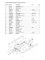
Jet Tools XACTA
The Jet Tools XACTA is a high-quality commercial fence system designed to enhance the accuracy and precision of your table saw operations. With its robust construction and user-friendly features, the XACTA fence is an excellent choice for both professional woodworkers and serious hobbyists.
Capabilities and Use Cases:
-
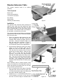
Precise Cuts: The XACTA's precision-machined aluminum rails and adjustable cursor ensure accurate and repeatable cuts, making it ideal for fine woodworking, cabinetry, and other projects requiring high levels of accuracy.
-
Versatile: The modular design of the XACTA fence allows for easy customization and integration with various table saws. Its compatibility with different extension tables and accessories expands its functionality, making it suitable for a wide range of sawing applications.
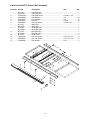
Jet Tools XACTA
The Jet Tools XACTA is a high-quality commercial fence system designed to enhance the accuracy and precision of your table saw operations. With its robust construction and user-friendly features, the XACTA fence is an excellent choice for both professional woodworkers and serious hobbyists.
Capabilities and Use Cases:
-
Precise Cuts: The XACTA's precision-machined aluminum rails and adjustable cursor ensure accurate and repeatable cuts, making it ideal for fine woodworking, cabinetry, and other projects requiring high levels of accuracy.
-
Versatile: The modular design of the XACTA fence allows for easy customization and integration with various table saws. Its compatibility with different extension tables and accessories expands its functionality, making it suitable for a wide range of sawing applications.


-
 1
1
-
 2
2
-
 3
3
-
 4
4
-
 5
5
-
 6
6
-
 7
7
-
 8
8
-
 9
9
-
 10
10
-
 11
11
-
 12
12
-
 13
13
-
 14
14
-
 15
15
-
 16
16


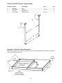
Jet Tools XACTA
The Jet Tools XACTA is a high-quality commercial fence system designed to enhance the accuracy and precision of your table saw operations. With its robust construction and user-friendly features, the XACTA fence is an excellent choice for both professional woodworkers and serious hobbyists.
Capabilities and Use Cases:
-
Precise Cuts: The XACTA's precision-machined aluminum rails and adjustable cursor ensure accurate and repeatable cuts, making it ideal for fine woodworking, cabinetry, and other projects requiring high levels of accuracy.
-
Versatile: The modular design of the XACTA fence allows for easy customization and integration with various table saws. Its compatibility with different extension tables and accessories expands its functionality, making it suitable for a wide range of sawing applications.
Ask a question and I''ll find the answer in the document
Finding information in a document is now easier with AI
Related papers
-
Jet Tools SuperSaw JWSS-10CS User manual
-
-
-
-
-
-
-
-
-
Other documents
-
AmeriHome 802993 Installation guide
-
JET XACTA Owner's manual
-
Atlantic 63735423 User manual
-
-
Powermatic PWBS14 User manual
-
-
-
Kohler 9653-0 Installation guide
-
Wilton JWBS-16B User manual
-
JET Deluxe Xacta® SAW 3HP, 1Ph, 30" Rip Owner's manual