Page is loading ...

Repair/Parts
ProMix
®
2KE
Plural Component Proportioner
3A0870L
EN
Self-contained, electronic plural component paint proportioner. For professional use only.
See pages 3 and 4 for model information, including maximum working pressure and approvals.
For patent information, see www.graco.com/patents
Important Safety Instructions
Read all warnings and instructions in this
manual. Save these instructions.
ti15698ati15696a
Pump System Meter System

2 3A0870L
Contents
Related Manuals . . . . . . . . . . . . . . . . . . . . . . . . . . . 3
Non-Hazardous Location Models . . . . . . . . . . . . . . 3
Hazardous Location Models . . . . . . . . . . . . . . . . . . 4
Warnings . . . . . . . . . . . . . . . . . . . . . . . . . . . . . . . . . 5
Important Two-Component Material Information . 8
Isocyanate Conditions . . . . . . . . . . . . . . . . . . . . . 8
Material Self-ignition . . . . . . . . . . . . . . . . . . . . . . 8
Keep Components A and B Separate . . . . . . . . . 8
Moisture Sensitivity of Isocyanates . . . . . . . . . . . 8
Changing Materials . . . . . . . . . . . . . . . . . . . . . . . 8
Pressure Relief Procedure . . . . . . . . . . . . . . . . . . . 9
Pump Systems . . . . . . . . . . . . . . . . . . . . . . . . . . 9
Meter Systems . . . . . . . . . . . . . . . . . . . . . . . . . . 9
Purging . . . . . . . . . . . . . . . . . . . . . . . . . . . . . . . . . . 10
Pump Systems . . . . . . . . . . . . . . . . . . . . . . . . . 10
Meter Systems . . . . . . . . . . . . . . . . . . . . . . . . . 11
Shutdown . . . . . . . . . . . . . . . . . . . . . . . . . . . . . . . . . 12
Maintenance Recommendations . . . . . . . . . . . . . . . 12
Service . . . . . . . . . . . . . . . . . . . . . . . . . . . . . . . . . . 13
Before Servicing . . . . . . . . . . . . . . . . . . . . . . . . 13
Replace the Air Filter Element . . . . . . . . . . . . . 13
Replace Solenoids . . . . . . . . . . . . . . . . . . . . . . 14
Replace the Power Supply . . . . . . . . . . . . . . . . 15
Replace Alternator Regulator . . . . . . . . . . . . . . 18
Replace Advanced Fluid Control
Module (AFCM) . . . . . . . . . . . . . . . . . . . . . 18
Replace Alarm . . . . . . . . . . . . . . . . . . . . . . . . . 19
Replace Display Module . . . . . . . . . . . . . . . . . . 19
Replace USB Module . . . . . . . . . . . . . . . . . . . . 20
Update Software . . . . . . . . . . . . . . . . . . . . . . . . 20
Pump System Air Controls . . . . . . . . . . . . . . . . 22
Meter System Air Controls . . . . . . . . . . . . . . . . 23
Fluid Controls . . . . . . . . . . . . . . . . . . . . . . . . . . 25
Repair Flow Meters . . . . . . . . . . . . . . . . . . . . . . 27
Repair Mix Manifold . . . . . . . . . . . . . . . . . . . . . 27
Pump Assembly . . . . . . . . . . . . . . . . . . . . . . . . 29
Parts . . . . . . . . . . . . . . . . . . . . . . . . . . . . . . . . . . . . 30
Pump-Based Proportioners, Models
24F088-24F115 . . . . . . . . . . . . . . . . . . . . . 30
Pumps . . . . . . . . . . . . . . . . . . . . . . . . . . . . . . . . 31
Air Controls, Pump-Based Models
24F088-24F115 . . . . . . . . . . . . . . . . . . . . . 35
Tubing Chart, Pump-Based Models
24F088-24F115 . . . . . . . . . . . . . . . . . . . . . 36
Meter-Based Proportioners, Models
24F080-24F087 . . . . . . . . . . . . . . . . . . . . . 38
Tubing Chart, Meter-Based Models
24F080-24F087 . . . . . . . . . . . . . . . . . . . . . 41
Control Box . . . . . . . . . . . . . . . . . . . . . . . . . . . . 43
USB Module . . . . . . . . . . . . . . . . . . . . . . . . . . . 44
Electric Power Assembly . . . . . . . . . . . . . . . . . . 45
Alternator Power Assembly . . . . . . . . . . . . . . . . 46
Alternator Module 255728 . . . . . . . . . . . . . . . . . 47
Sequential Dosing Mix Manifold 262398 . . . . . . 48
Dynamic Dosing Mix Manifold 262399 . . . . . . . 48
1-Color/1 Solvent Valve Stack . . . . . . . . . . . . . . 49
3-Color/1 Solvent Valve Stack . . . . . . . . . . . . . . 49
Pump Stand Kit 24F301
Meter Stand Kit 24G611 . . . . . . . . . . . . . . . 50
Air Flow Switch Kit 15T632 . . . . . . . . . . . . . . . . 50
Accessories . . . . . . . . . . . . . . . . . . . . . . . . . . . . . . 51
Schematics . . . . . . . . . . . . . . . . . . . . . . . . . . . . . . . 52
Technical Data . . . . . . . . . . . . . . . . . . . . . . . . . . . . 59
Graco Standard Warranty . . . . . . . . . . . . . . . . . . . 60

Related Manuals
3A0870L 3
Related Manuals
Non-Hazardous Location Models
*
* ProMix 2KE non-hazardous location equipment manufactured in the United States, with serial number beginning
with A or 01, has FM and CE approvals. Equipment manufactured in Belgium, with serial number beginning with
M or 38, has CE approval.
Manual Description
3A0868 ProMix 2KE, Pump-Based, Operation
3A0869 ProMix 2KE, Meter-Based, Operation
313599 Coriolis Meter
308778 G3000 Flow Meter
312781 Fluid Mix Manifold
312782 Dosing Valve
312784 Gun Flush Box Kit 15V826
312792 Merkur Displacement Pump
312793 Merkur Bellows Displacement Pump
312796 NXT Air Motor
406714 Rebuild Kit for High Pressure
Dispense Valve
406823 Dispense Valve Seat Kits
3A1244 Graco Control Architecture
Module Programming
3A1323 16G353 Alternator Conversion Kit
3A1324 16G351 Electric Power Conversion Kit
3A1325 ProMix 2KE Stand Kits
3A1332 24H255 3-Color Valve Stack Kit
3A1333 24H253 USB Module Kit
313542 Beacon Tower
Manual Description
Approved for Non-Hazardous Location
Part No. Series Description
Maximum Working
Pressure
psi (MPa, bar)
USB
Module Approvals*
Pump Systems
24F088 A 3:1, Merkur, A and B 300 (2.1, 21)
24F089 A 23:1, Merkur, A and B 2300 (15.8, 158)
24F090 A 30:1, Merkur, A and B 3000 (20.7, 207)
24F091 A 45:1, Merkur, A and B 4500 (31.0, 310)
24F092 A 3:1, Merkur A, Merkur Bellows B 300 (2.1, 21)
24F093 A 23:1, Merkur A, Merkur Bellows B 2300 (15.8, 158)
24F094 A 35:1, Merkur A, Merkur Bellows B 3500 (24.1, 241)
✔
24F095 A 3:1, Merkur, A and B 300 (2.1, 21)
✔
24F096 A 23:1, Merkur, A and B 2300 (15.8, 158)
✔
24F097 A 30:1, Merkur, A and B 3000 (20.7, 207)
✔
24F098 A 45:1, Merkur, A and B 4500 (31.0, 310)
✔
24F099 A 3:1, Merkur A, Merkur Bellows B 300 (2.1, 21)
✔
24F100 A 23:1, Merkur A, Merkur Bellows B 2300 (15.8, 158)
✔
24F101 A 35:1, Merkur A, Merkur Bellows B 3500 (24.1, 241)
✔
Meter Systems
24F080 A G3000, 1 color/1 catalyst 3000 (27.58, 275.8)
24F081 A G3000, 3 colors/1 catalyst 3000 (27.58, 275.8)
24F082 A G3000, 1 color/1 catalyst 3000 (27.58, 275.8)
✔
24F083 A G3000, 3 colors/1 catalyst 3000 (27.58, 275.8)
✔
# 53

Hazardous Location Models
4 3A0870L
Hazardous Location Models
* ProMix 2KE hazardous location equipment manufactured in the United States, with serial number beginning with
A or 01, has ATEX, FM, and CE approvals, as noted. Equipment manufactured in Belgium, with serial number
beginning with M or 38, has ATEX and CE approvals, as noted.
ProMix 2KE systems are not approved for use in hazardous locations unless the base model,
all accessories, all kits, and all wiring meet local, state, and national codes.
Approved for Hazardous Location
Class 1, Div 1, Group D (North America); Class 1, Zones 1 and 2 (Europe)
Part No. Series Description
Maximum Working
Pressure
psi (MPa, bar)
USB
Module Approvals*
Pump Systems
24F102 A 3:1, Merkur, A and B 300 (2.1, 21)
24F103 A 23:1, Merkur, A and B 2300 (15.8, 158)
24F104 A 30:1, Merkur, A and B 3000 (20.7, 207)
24F105 A 45:1, Merkur, A and B 4500 (31.0, 310)
24F106 A 3:1, Merkur A, Merkur Bellows B 300 (2.1, 21)
24F107 A 23:1, Merkur A, Merkur Bellows B 2300 (15.8, 158)
24F108 A 35:1, Merkur A, Merkur Bellows B 3500 (24.1, 241)
24F109 A 3:1, Merkur, A and B 300 (2.1, 21)
✔
24F110 A 23:1, Merkur, A and B 2300 (15.8, 158)
✔
24F111 A 30:1, Merkur, A and B 3000 (20.7, 207)
✔
24F112 A 45:1, Merkur, A and B 4500 (31.0, 310)
✔
24F113 A 3:1, Merkur A, Merkur Bellows B 300 (2.1, 21)
✔
24F114 A 23:1, Merkur A, Merkur Bellows B 2300 (15.8, 158)
✔
24F115 A 35:1, Merkur A, Merkur Bellows B 3500 (24.1, 241)
✔
Meter Systems
24F084 A G3000, 1 color/1 catalyst 3000 (27.58, 275.8)
24F085 A G3000, 3 colors/1 catalyst 3000 (27.58, 275.8)
24F086 A G3000, 1 color/1 catalyst 3000 (27.58, 275.8)
✔
24F087 A G3000, 3 colors/1 catalyst 3000 (27.58, 275.8)
✔
# 53
0359
Ex ia px IIA T3 Ta = 0°C to 54°C
FM10 ATEX 0025 X
II 2 G
Intrinsically safe and purged
equipment for
Class I, Division 1, Group D, T3
Ta = 0°C to 54°C
See Special Conditions for Safe
Use in Warnings, page 5.

Warnings
3A0870L 5
Warnings
The following warnings are for the setup, use, grounding, maintenance, and repair of this equipment. The exclama-
tion point symbol alerts you to a general warning and the hazard symbols refer to procedure-specific risks. When
these symbols appear in the body of this manual, refer back to these Warnings. Product-specific hazard symbols and
warnings not covered in this section may appear throughout the body of this manual where applicable.
WARNING
FIRE AND EXPLOSION HAZARD
Flammable fumes, such as solvent and paint fumes, in work area can ignite or explode. To help prevent
fire and explosion:
• Use equipment only in well ventilated area.
• Eliminate all ignition sources; such as pilot lights, cigarettes, portable electric lamps, and plastic drop
cloths (potential static arc).
• Keep work area free of debris, including solvent, rags and gasoline.
• Do not plug or unplug power cords, or turn power or light switches on or off when flammable fumes are
present.
• Ground all equipment in the work area. See Grounding instructions.
• Use only grounded hoses.
• Hold gun firmly to side of grounded pail when triggering into pail.
• If there is static sparking or you feel a shock, stop operation immediately. Do not use equipment until
you identify and correct the problem.
• Keep a working fire extinguisher in the work area.
SPECIAL CONDITIONS FOR SAFE USE
• To prevent the risk of electrostatic sparking, the equipment’s non-metallic parts should be cleaned only
with a damp cloth.
• Pump Systems: The aluminum adapter plate may spark upon impact or contact with moving parts,
which may cause fire or explosion. Take precautions to avoid such impact or contact.
ELECTRIC SHOCK HAZARD
This equipment must be grounded. Improper grounding, setup, or usage of the system can cause electric
shock.
• Turn off and disconnect power at main switch before disconnecting any cables and before servicing
equipment.
• Connect only to grounded power source.
• All electrical wiring must be done by a qualified electrician and comply with all local codes and
regulations.

Warnings
6 3A0870L
INTRINSIC SAFETY
Intrinsically safe equipment that is installed improperly or connected to non-intrinsically safe equipment
will create a hazardous condition and can cause fire, explosion, or electric shock. Follow local regulations
and the following safety requirements.
• Only models with model numbers 24F084-24F087 and 24F102-24F115, utilizing the air-driven
alternator, are approved for installation in a Hazardous (explosive atmosphere) Location. See
Hazardous Location Models, page 4.
• Be sure your installation complies with national, state, and local codes for the installation of electrical
apparatus in a Class I, Group D, Division 1 (North America) or Class I, Zones 1 and 2 (Europe)
Hazardous Location, including all of the local safety fire codes, NFPA 33, NEC 500 and 516, and
OSHA 1910.107.
• To help prevent fire and explosion:
•Do not install equipment approved only for a non-hazardous location in a hazardous location. See
model ID label for the intrinsic safety rating of your model.
•Do not substitute system components as this may impair intrinsic safety.
• Equipment that comes in contact with the intrinsically safe terminals must be rated for Intrinsic Safety.
This includes DC voltage meters, ohmmeters, cables, and connections. Remove the unit from the
hazardous area when troubleshooting.
• The equipment is intrinsically safe when no external electrical components are connected to it.
• Do not connect, download, or remove USB device unless unit is removed from the hazardous
(explosive atmosphere) location.
SKIN INJECTION HAZARD
High-pressure fluid from gun, hose leaks, or ruptured components will pierce skin. This may look like just
a cut, but it is a serious injury that can result in amputation. Get immediate surgical treatment.
• Do not spray without tip guard and trigger guard installed.
• Engage trigger lock when not spraying.
• Do not point gun at anyone or at any part of the body.
• Do not put your hand over the spray tip.
• Do not stop or deflect leaks with your hand, body, glove, or rag.
• Follow the Pressure Relief Procedure when you stop spraying and before cleaning, checking, or
servicing equipment.
• Tighten all fluid connections before operating the equipment.
• Check hoses and couplings daily. Replace worn or damaged parts immediately.
WARNING

Warnings
3A0870L 7
EQUIPMENT MISUSE HAZARD
Misuse can cause death or serious injury.
• Do not operate the unit when fatigued or under the influence of drugs or alcohol.
• Do not exceed the maximum working pressure or temperature rating of the lowest rated system
component. See Technical Data in all equipment manuals.
• Use fluids and solvents that are compatible with equipment wetted parts. See Technical Data in all
equipment manuals. Read fluid and solvent manufacturer’s warnings. For complete information about
your material, request MSDS from distributor or retailer.
• Do not leave the work area while equipment is energized or under pressure. Turn off all equipment and
follow the Pressure Relief Procedure when equipment is not in use.
• Check equipment daily. Repair or replace worn or damaged parts immediately with genuine
manufacturer’s replacement parts only.
• Do not alter or modify equipment.
• Use equipment only for its intended purpose. Call your distributor for information.
• Route hoses and cables away from traffic areas, sharp edges, moving parts, and hot surfaces.
• Do not kink or over bend hoses or use hoses to pull equipment.
• Keep children and animals away from work area.
• Comply with all applicable safety regulations.
MOVING PARTS HAZARD
Moving parts can pinch, cut or amputate fingers and other body parts.
• Keep clear of moving parts.
• Do not operate equipment with protective guards or covers removed.
• Pressurized equipment can start without warning. Before checking, moving, or servicing equipment,
follow the Pressure Relief Procedure and disconnect all power sources.
TOXIC FLUID OR FUMES HAZARD
Toxic fluids or fumes can cause serious injury or death if splashed in the eyes or on skin, inhaled, or
swallowed.
• Read MSDSs to know the specific hazards of the fluids you are using.
• Store hazardous fluid in approved containers, and dispose of it according to applicable guidelines.
• Always wear chemically impermeable gloves when spraying, dispensing, or cleaning equipment.
PERSONAL PROTECTIVE EQUIPMENT
You must wear appropriate protective equipment when operating, servicing, or when in the operating area
of the equipment to help protect you from serious injury, including eye injury, hearing loss, inhalation of
toxic fumes, and burns. This equipment includes but is not limited to:
• Protective eyewear, and hearing protection.
• Respirators, protective clothing, and gloves as recommended by the fluid and solvent manufacturer.
WARNING

Important Two-Component Material Information
8 3A0870L
Important Two-Component Material Information
Isocyanate Conditions
Material Self-ignition
Keep Components A and B
Separate
Moisture Sensitivity of
Isocyanates
Isocyanates (ISO) are catalysts used in two component
coatings. ISO will react with moisture (such as humidity)
to form small, hard, abrasive crystals, which become
suspended in the fluid. Eventually a film will form on the
surface and the ISO will begin to gel, increasing in vis-
cosity. If used, this partially cured ISO will reduce perfor-
mance and the life of all wetted parts.
NOTE: The amount of film formation and rate of crystal-
lization varies depending on the blend of ISO, the
humidity, and the temperature.
To prevent exposing ISO to moisture:
• Always use a sealed container with a desiccant
dryer in the vent, or a nitrogen atmosphere. Never
store ISO in an open container.
• Use moisture-proof hoses specifically designed for
ISO, such as those supplied with your system.
• Never use reclaimed solvents, which may contain
moisture. Always keep solvent containers closed
when not in use.
• Never use solvent on one side if it has been con-
taminated from the other side.
• Always lubricate threaded parts with ISO pump oil
or grease when reassembling.
Changing Materials
• When changing materials, flush the equipment mul-
tiple times to ensure it is thoroughly clean.
• Always clean the fluid inlet strainers after flushing.
• Check with your material manufacturer for chemical
compatibility.
Spraying or dispensing materials containing
isocyanates creates potentially harmful mists, vapors,
and atomized particulates.
Read material manufacturer’s warnings and material
MSDS to know specific hazards and precautions
related to isocyanates.
Prevent inhalation of isocyanate mists, vapors, and
atomized particulates by providing sufficient
ventilation in the work area. If sufficient ventilation is
not available, a supplied-air respirator is required for
everyone in the work area.
To prevent contact with isocyanates, appropriate
personal protective equipment, including chemically
impermeable gloves, boots, aprons, and goggles, is
also required for everyone in the work area.
Some materials may become self-igniting if applied
too thickly. Read material manufacturer’s warnings
and material MSDS.
Cross-contamination can result in cured material in
fluid lines which could cause serious injury or
damage equipment. To prevent cross-contamination
of the equipment’s wetted parts, never interchange
component A (resin) and component B (isocyanate)
parts.

Pressure Relief Procedure
3A0870L 9
Pressure Relief Procedure
NOTE: The following procedure relieves all fluid and air
pressure in the ProMix 2KE system.
Pump Systems
1. Press on Run Mix Spray (Screen 2) or
from any screen to put the system in Standby.
2. Follow procedure for Purging Fluid Supply Sys-
tem, page 10, if desired or necessary.
3. Shut off air supply to A and B pumps and solvent
supply pumps.
4. With the gun triggered, push the manual override on
the A and B dose and solvent valve solenoids to
relieve pressure. See F
IG
. 1, page 12. Verify that
fluid pressure is reduced to 0.
5. Reinstall the Control Box cover.
Meter Systems
1. Press on Run Mix Spray (Screen 2) or
from any screen to put the system in Standby.
2. Shut off the A1 (A2 and A3, if using multiple colors)
and B fluid supply pumps/pressure pots.
3. Remove the Control Box cover.
4. With the gun triggered, push the manual override on
the A1 (A2, A3), and B dose valve solenoids to
relieve pressure. See F
IG
. 1, page 12.
5. Follow Purging procedure, page 11.
6. Shut off the fluid supply to solvent valves A and B.
7. With the gun triggered, push the manual override on
the A and B solvent valve solenoids to relieve sol-
vent pressure. See F
IG
. 1. Verify that solvent pres-
sure is reduced to 0.
8. Reinstall the Control Box cover.
To reduce the risk of skin injection, relieve pressure
when you stop spraying, before changing spray tips,
and before cleaning, checking, or servicing
equipment.

Purging
10 3A0870L
Purging
Pump Systems
There are 2 pump purging procedures in this manual:
• Purging Mixed Material
• Purging Fluid Supply System
Use the criteria listed for each procedure to determine
which procedure to use.
Purging Mixed Material
There are times when you only want to purge the fluid
manifold, such as:
• end of potlife
• breaks in spraying that exceed the potlife
• overnight shutdown
• before servicing the fluid manifold assembly, hose
or gun.
1. Press on Run Mix Spray (Screen 2) or
from any screen to put the system in Standby.
2. Trigger the gun to relieve pressure.
3. If you are using a high pressure gun, engage the
trigger lock. Remove spray tip and clean tip sepa-
rately.
4. If using an electrostatic gun shut off the electrostat-
ics before flushing the gun.
5. Set the solvent supply pressure regulator at a pres-
sure high enough to completely purge the system in
a reasonable amount of time but low enough to
avoid splashing or an injection injury. Generally, a
setting of 100 psi (0.7 MPa, 7 bar) is sufficient.
6. If using a gun flush box, place the gun into the box
and close the lid. Press on Run Mix Spray
(Screen 2). The purge sequence automatically
starts.
If the gun flush box is not used, trig-
ger the gun into a grounded metal
pail until the purge sequence is com-
plete.
When done purging, the system automatically
switches to Standby mode.
7. If the system is not completely clean, repeat step 6.
NOTE: If necessary, adjust purge sequence so only
one cycle is required.
8. Trigger the gun to relieve pressure. Engage trigger
lock.
9. If spray tip was removed, reinstall it.
10. Adjust the solvent supply regulator back to its nor-
mal operating pressure.
NOTE: If your system uses 2 guns, you must trigger
both guns simultaneously during a purge to purge both
guns and lines. Verify that clean solvent flows from each
gun. If not, repeat purge or clear clog/blockage in sys-
tem.
Purging Fluid Supply System
Follow this procedure before:
• the first time material is loaded into equipment
• servicing
• shutting down equipment for an extended period of
time
• putting equipment into storage
1. Press on Run Mix Spray (Screen 2) or
from any screen to put the system in Standby.
2. Trigger the gun to relieve pressure.
3. If you are using a high pressure gun, engage the
trigger lock. Remove spray tip and clean tip sepa-
rately.
4. If using an electrostatic gun, shut off the electrostat-
ics before flushing the gun.

Purging
3A0870L 11
5. Disconnect the component A and B fluid supplies at
the pump inlets, and connect solvent supply lines.
6. Adjust the solvent fluid supply pressure. Use the
lowest possible pressure to avoid splashing.
7. Remove the Control Box cover to access the sole-
noid valves. See F
IG
. 1, page 12.
8. Purge as follows:
• Purge component A side. See F
IG
. 1, page 12.
Press the manual override on the Dose Valve A
solenoid valve and trigger the gun into a
grounded metal pail.
Purge component B side. Press the manual
override on the Dose Valve B solenoid valve
and trigger the gun into a grounded metal pail
until clean solvent flows from the gun.
Repeat to thoroughly clean the mix manifold.
9. Reinstall the Control Box cover.
10. Shut off the solvent fluid supply.
11. Disconnect the solvent supply lines and reconnect
the component A and B fluid supplies.
NOTE: If your system uses 2 guns, you must trigger
both guns simultaneously during a purge to purge both
guns and lines. Verify that clean solvent flows from each
gun. If not, repeat purge or clear clog/blockage in sys-
tem.
NOTE: The system remains full of solvent.
Meter Systems
Purge the system:
• at the end of potlife
• breaks in spraying that exceed the potlife
• overnight shutdown or end of shift
• the first time material is loaded into equipment
• servicing
• shutting down equipment for an extended period of
time
1. Press on Run Mix Spray (Screen 2) or
from any screen to put the system in Standby.
2. Trigger the gun to relieve pressure.
3. If you are using a high pressure gun, engage the
trigger lock. Remove spray tip and clean tip sepa-
rately.
4. If using an electrostatic gun shut off the electrostat-
ics before flushing the gun.
5. Set the solvent supply pressure regulator at a pres-
sure high enough to completely purge the system in
a reasonable amount of time but low enough to
avoid splashing or an injection injury. Generally, a
setting of 100 psi (0.7 MPa, 7 bar) is sufficient.
6. If using a gun flush box, place the gun into the box
and close the lid.
7. Press on Run Mix Spray (Screen 2). The
purge sequence automatically starts.
If the gun flush box is not used, trig-
ger the gun into a grounded metal
pail until the system returns to
Standby mode.
8. If the system is not completely clean, repeat step 6.
NOTE: If necessary, adjust purge sequence so only
one cycle is required.
9. Trigger the gun to relieve pressure. Engage trigger
lock.
10. If spray tip was removed, reinstall it.
11. Adjust the solvent supply regulator back to its nor-
mal operating pressure.
NOTE: The system remains full of solvent.
NOTE: If your system uses 2 guns, you must trigger
both guns simultaneously during a purge to purge both
guns and lines. Verify that clean solvent flows from each
gun. If not, repeat purge or clear clog/blockage in sys-
tem.

Purging
12 3A0870L
Shutdown
1. Follow Purging procedure for your system, page 10
or 11.
2. Close main air shutoff valve on air supply line and
on ProMix 2KE.
3. Non-IS Systems: Shut off ProMix 2KE power
(0 position). NOTE: Meter-based systems will
restart in Recipe 0.
Maintenance
Recommendations
The following table shows starting maintenance recom-
mendations. Maintenance needs will vary based on indi-
vidual applications and material differences.
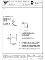
F
IG
. 1. Solenoid Valves in Control Box
Solvent Valve A
Solenoid
Manual Overrides
Dose Valve A1
Solenoid
Solvent Valve B
Solenoid
Dose Valve B
Solenoid
Dose Valve A2
Solenoid Location
Dose Valve A3
Solenoid Location
ti15730a
Gun Flush Box
Solenoid Location
Component
Recommended Maintenance
Frequency
Solvent Valves 1,000,000 cycles
Fluid Filter daily
Air Filter monthly
Pumps 250,000 cycles
Dose Valves 1,000,000 cycles
Meters 5,000 gallons

Service
3A0870L 13
Service
Before Servicing
1. Follow Pressure Relief Procedure, page 9, if ser-
vice time may exceed pot life time, before servicing
fluid components, and before transporting equip-
ment to a service area.
2. Close air shutoff valves.
3. Non-IS Systems: Shut off power (0 position).
4. If servicing Control Box, also shut off power at main
circuit breaker.
Replace the Air Filter Element
Pump systems have two air filters: the 5 micron air man-
ifold filter (209) and the 40 micron pump air filter (206).
Meter systems have only the 5 micron filter (209). Check
filters daily and replace element(s) as needed. Order
15D909 (5 micron) or 15D890 (40 micron).
1. Close main air shutoff valve on air supply line and
on system. Depressurize air line.
2. Remove the filter cover (A).
3. Unscrew the filter bowl (B).
4. Remove and replace element (206a, 209a).
5. Screw filter bowl (B) on securely. Install cover (A).
• To avoid electric shock, turn off power before
servicing.
• Servicing the Control Box exposes you to high
voltage. Shut off power at main circuit breaker
before opening enclosure.
• All electrical wiring must be done by a qualified
electrician and comply with all local codes and
regulations.
• Do not substitute system components as this may
impair intrinsic safety.
• Read Warnings, pages 5- 8.
Removing a pressurized air filter bowl could cause seri-
ous injury. Depressurize air line before servicing.
F
IG
. 2. Replace Air Filter Element(s)
Pump
System
Meter
System
209
206
209
A
B
206a, 209a
ti15708a
ti16437a
ti12691a

Service
14 3A0870L
Replace Solenoids
The system has a minimum of 4 solenoids. If you have a
3-color system or a gun flush box, you have additional
(optional) solenoids for each.
To replace a single solenoid:
1. Follow Before Servicing, page 13. Disconnect
main power.
2. Open Control Box.
3. Disconnect 2 solenoid wires (N) from harness (320).
See F
IG
. 3.
4. Unscrew 2 screws (P) and remove solenoid (306).
5. Install new solenoid (306).
6. Connect 2 wires (N) to harness (320). Solenoid
wires are polarized (red+, black-). Refer to System
Electrical Schematics, pages 54-57.
7. Replace Control Box cover.
To replace the solenoid module:
1. Follow Before Servicing, page 13. Disconnect
main power.
2. Open Control Box.
3. Disconnect all solenoid wires (N) from harnesses
(320).
NOTE: If you have an intrinsically safe model, you will
need to remove the alternator air regulator from the
solenoid module. See page 18 for removal instructions.
4. Remove two screws (305).
5. Remove and replace solenoid module.
6. Connect all wires (N) to harnesses (320). Solenoid
wires are polarized (red+, black-). Refer to System
Electrical Schematics, pages 54-57.
7. Replace Control Box cover.
F
IG
. 3. Replace a Single Solenoid
ti16646a
N
320
306
P
320
F
IG
. 4. Replace Solenoid Module
305
ti16450a

Service
3A0870L 15
Replace the Power Supply
Wall Power Supply and Filter
1. Follow Before Servicing, page 13. Disconnect
main power.
2. Open Control Box.
3. Disconnect the three input wires from the line filter
(403).
4. See F
IG
. 8. Disconnect the power supply CAN cable
(401a) from the advanced fluid control module
(302).
5. Disconnect line filter wires and power supply wires
from the power switch (402).
6. Disconnect the power supply ground wire,
PS(GND), from the advanced fluid control module
ground terminal (T).
7. Remove four screws (405) and remove power sup-
ply (401). If replacing filter, remove two screws
(407) and the filter (403).
8. Install the new power supply (401) and line filter
(403), using supplied screws (405, 407), as shown.
9. See F
IG
. 8. Connect wire harness (410/LF) to the
line filter (403) and to the power switch (402), as
shown. See also Electrical schematic.
10. Connect the power supply wire harness (411/PS) to
the switch (402), as shown. See also Electrical
Schematic. Connect the PS ground wire to the
ground terminal (T) of the advanced fluid control
module.
11. See F
IG
. 5. Connect wire harness (411) to the line
filter (403) and terminal block (404) as shown. See
also Electrical Schematic.
12. Connect CAN cable (401a) to the advanced fluid
control module.
All electrical wiring must be completed by a qualified
electrician and comply with all local codes and
regulations.
F
IG
. 5. Terminal Block Electrical Connections
Line
Neutral
Ground
411
404
403
ti16391a
F
IG
. 6. Reconnect CAN cable.
F
IG
. 7. Electrical Schematic
Connect cable
(401a) here.
ti16602a
LINE POWER
FILTER
POWER
SUPPLY
TERMINAL
BLOCK
SWITCH
ROCKER
1A
1
2A
2
L N GRND
L GRND N
L N

Service
16 3A0870L
F
IG
. 8. Replace Wall Power Supply
405
401
407
ti16454a
401a
302
1: PS(N)
1A: LF(N)
2: PS(L)
1A: LF(N)
403
402
LF(L)
LF(N)
PS(L)
PS(N)
PS(GND)
T
406

Service
3A0870L 17
Alternator Power Supply and Turbine
1. Follow Before Servicing, page 13. Disconnect
main air.
2. Open Control Box.
3. See F
IG
. 9. Disconnect output power cable connec-
tions from alternator module (501). Disconnect
ground lead (G) from control box ground terminal
(T).
4. Disconnect the power supply cables from the
Advanced Fluid Control Module, the USB Module,
and the Display Module.
5. Disconnect air regulator line and exhaust air line
from alternator module.
6. Remove four screws (509) from mounting to remove
alternator from control box.
7. Remove seven screws (501h) to separate alternator
housings.
8. Replace turbine (501d) if necessary. Lightly lubri-
cate turbine o-ring to ease alternator housing reas-
sembly.
9. Follow steps in reverse order to reassemble alterna-
tor regulator assembly and to reconnect power
F
IG
. 9. Remove Alternator Module (and Turbine)
501
Supply line
disconnect
Exhaust air line
disconnect
509
G
T
Cable
connectors
Air regulator line
501h
501d
ti16456a
ti16455a

Service
18 3A0870L
Replace Alternator Regulator
1. Follow Before Servicing, page 13. Disconnect
main air.
2. Open Control Box.
3. Disconnect supply air line from regulator assembly
(505).
4. Loosen air regulator swivel fittings (506) and
remove from solenoid module.
5. Repair or replace alternator regulator parts as nec-
essary. See Alternator Power Assembly, page 46,
for repair parts. Replace air regulator swivel fitting
(506).
6. Reconnect air line. Set regulator air pressure to
18 psi (0.12 MPa, 1.2 bar).
7. Close Control Box and restore power.
Replace Advanced Fluid Control
Module (AFCM)
1. Follow Before Servicing, page 13. Disconnect
main power.
2. Open Control Box.
3. Remove all cables from AFCM (302). Take note of
cable locations.
4. Disconnect ground wire from ground screw (GS).
5. Loosen four mounting screws (303).
6. Slide AFCM up and out of keyhole slots.
7. Follow steps in reverse order to install a new AFCM.
See electrical schematic for cable connection infor-
mation.
8. Follow instructions in Manual 3A1244 to update the
software on the new AFCM.
9. Close Control Box and restore power.
NOTICE
To avoid damage to the alternator, do not set
the regulator air pressure higher than 18 psi
(0.12 MPa, 1.2 bar).
F
IG
. 10. Replace Alternator Regulator
ti16456a
506
505
Solenoid
Module
Air regulator line
F
IG
. 11. Replace AFCM
303
302
ti16452a
GS

Service
3A0870L 19
Replace Alarm
1. Follow Before Servicing, page 13. Disconnect
main power.
2. Open Control Box.
3. Disconnect alarm wires from alarm (311).
4. Unscrew alarm jam/mounting nut to remove alarm.
5. Assemble new alarm. Reconnect alarm wires.
6. Close Control Box and restore power.
Replace Display Module
1. Follow Before Servicing, page 13.
2. The Display Module (63) snaps tightly into the
mounting bracket (49). To remove it, lift up on the
front of the bracket and, at the same time, pull the
Display Module out.
3. Disconnect the CAN cable (64).
4. Replace with a new Display Module.
5. Reconnect the CAN cable (64) as shown.
6. Follow instructions in Manual 3A1244 to update the
software on the new Display Module.
F
IG
. 12. Replace Alarm
311
ti16453a
F
IG
. 13. Replace Display Module
Lift here.
Connect cable (64) here
(either port).
J6
ti16672a
ti16604a
64

Service
20 3A0870L
Replace USB Module
1. Follow Before Servicing, page 13. Disconnect
main power.
2. Open Control Box.
3. Non-IS Systems: Disconnect Display Module CAN
cable, Advanced Fluid Control Module CAN cable
and USB cable from the USB module (340).
IS Systems: Disconnect Alternator CAN cable and
USB cable from the USB module (340).
4. Remove ground screw (343) from top of Control Box
for USB module and bracket.
5. Remove four mounting screws (341) from USB
module and remove module.
6. Follow steps in reverse order to install a new USB
module.
Non-IS Systems Cable Connections:
• CAN cable from J6 (either port) on the Display
Module to P3 on the USB Module.
• CAN cable from J8 on the Advanced Fluid Con-
trol Module to P4 on the USB Module
• USB cable (345) from the port on the Control
Box to the port on the USB Module.
IS Systems Cable Connections:
• CAN cable from J2 on the Alternator Module to
P3 on the USB Module.
• USB cable (345) from the port on the Control
Box to the port on the USB Module.
7. Follow instructions in Manual 3A1244 to update the
software on the new USB Module.
8. Close Control Box and restore power.
Update Software
Order Software Token Kit 16D922 to update software.
Manuals 3A1244 and 406905 will accompany all soft-
ware updates. Follow all instructions and warnings in
these manuals to update your Display Module,
Advanced Fluid Control Module, and USB Module (if
used).
To help prevent fire and explosion, do not connect,
download, or remove the USB flash drive unless the
unit is removed from the hazardous (explosive
atmosphere) location. Never leave the USB flash
drive in the USB port.
F
IG
. 14. USB Non-IS Cable Connections
F
IG
. 15. USB IS Cable Connections.
USB Module
Advanced
Fluid Control
Module
Display Module
P4
P3
J6
J8
ti16580a
ti16604a
ti16579a
P3
J2
USB Module
Alternator Module
ti15710a
ti16580a
/