
PRODUCT DATA
® U.S. Registered Trademark
Copyright © 2001 Honeywell • • All Rights Reserved
T8000C, T8001C,T8024D
Programmable Thermostats
APPLICATION
The T8000C, T8001C and T8024D Programmable
Thermostats provide programmable temperature control for
24 Vac heating-cooling systems with manual changeover
from heat to cool. The T8000C and T001C provide single-
stage heating and cooling control and the T8024D provides
two-stage heating and two-stage cooling contorl. Heating
cycle rates are selectable at 1, 3, 4, 5, 6, 9, or 12 cph.
Cooling cycle rates are fixed at 3 cph. Temperature indication
can be set for °F or °C.
The T8000C is powered through the heating/cooling system
controls. The T8001C and T8024D are powered directly
through the system transformer.
FEATURES
• Attractive styling complements any decor to the
homeowner s delight.
• Preprogrammed for your convenience.
• Program up to four time periods and temperature
setpoints to complement your lifestyle.
• Programs are permanently held in non-volatile memory
in the event of a power failure.
• Indefinite setpoint temperature hold for added comfort
and energy savings.
• Ease-of-use means fewer homeowner questions and
increased homeowner satisfaction.
• Large temperature display for quick easy readability.
• Conveniently sized thermostat (5-1/2 x 3-1/2) with
optional decorator cover plates (7-3/8 x 5-3/4) make it
easy to install in a variety of locations.
• Keys are located by the display for easy access.
• FAN and SYSTEM switches are located on the lower
edge to eliminate accidental setting changes.
• Easy installation, setup and self-test saves time and
increases installer productivity.
• Manual changeover from heat to cool eliminates
unexpected system operation.
•
°F or °C temperature display for added model flexibility.
• Selectable heating cycle rate (1, 3, 4, 5, 6, 9 or 12 cph) for
a variety of applications which reduces the amount of
inventory.
• Cooling cycle rate is fixed (3 cph), the standard setting
for compressors, for speedy installation.
• Setpoints are permanently held in non-volatile memory
(no batteries required) and retained during power
outages for increased installer and homeowner
convenience.
• Power stealing and hardwired models available for
virtually all equipment and application needs including;
gas, oil and electric forced air, condensing gas furnaces,
forced air zoning systems, single stage heat pumps,
hydronic heat, gravity and radiant floor heat systems.
Contents
Application .......................................................................... 1
Features .............................................................................. 1
Specifications ...................................................................... 2
Ordering Information ........................................................... 2
Installation ........................................................................... 3
Installer Setup ..................................................................... 6
Operation ............................................................................ 8
Checkout ............................................................................. 9
Troubleshooting .................................................................. 12
68-0195-2

T8000C, T8001C AND T8024D PROGRAMMABLE THERMOSTATS
68-0195–2
2
ORDERING INFORMATION
When purchasing replacement and modernization products from your TRADELINE® wholesaler or distributor, refer to the
TRADELINE® Catalog or price sheets for complete ordering number.
If you have additional questions, need further information, or would like to comment on our products or services, please write or
phone:
1. Your local Home and Building Control Sales Office (check white pages of your phone directory).
2. Home and Building Control Customer Relations
Honeywell, 1885 Douglas Drive North, MN10-1461
Golden Valley, Minnesota 55422-4386 1-800-468-1502
In Canada—Honeywell Limited/Honeywell Limitée, 35 Dynamic Drive, Scarborough, Ontario M1V 4Z9.
International Sales and Service Offices in all principal cities of the world. Manufacturing in Australia, Canada, Finland, France,
Germany, Japan, Mexico, Netherlands, Spain, Taiwan, United Kingdom, U.S.A.
SPECIFICATIONS
IMPORTANT
The specifications given in this publication do not
include normal manufacturing tolerances; therefore,
an individual unit might not exactly match the listed
specifications. Also, this product is tested and
calibrated under closely controlled conditions, and
some minor differences in performance can be
expected if those conditions are changed.
The TRADELINE¤ models include a thermostat, wallplate
and owner s guide. A 7 3/8 in. x 5 3/4 in. (188 mm x 146 mm)
decorator cover plate (for covering wall marks) is available
separately. Order Honeywell part no. 209649A (taupe) or part
no. 209649B (white).
Power: 24 Vac nominal, 18 to 30 Vac, 50 or 60 Hz.
Electrical Ratings:
T8000C:
Heating: .02-1.2A run; 3.5A inrush.
Cooling: .02-1.2A run; 6.0A inrush.
T8001C and T8024D:
Heating: .02 to 1.5A run; 3.5A inrush.
Cooling: .02 to 1.5A run; 7.5A inrush.
T8000C, T8001C and T8024D:
Fan: .02 to 0.5A run; 2.5A inrush.
Current Draw:
T8000C Power Stealing Thermostat requires only 2.5 mA
current draw when the thermostat calls for heat and is
compatible with most 24V microprocessor systems. For
further detail, see Power Stealing in the OPERATION section.
Temperature Adjustment:
Setpoint temperature is adjusted by using the ▼ or ▲ keys.
One press changes the setpoint one degree; pressing and
holding changes the setpoint several degrees.
Temperature Setting Range: 30 to 99°F (4 to 37°C).
Ambient Temperature Range: 30 to 110°F (4 to 43°C).
Shipping Temperature Range: -20 to 120°F (-29 to 49°C).
Operating Relative Humidity: 5% to 90% RH, non-
condensing.
Cycle Rates (at 50% Load):
Heating: Selectable at 1, 3, 6, 9 or 12 cph. See Heating
Cycle Rates, Table 1, for cycle rate options and
corresponding system equipment.
Cooling: Fixed at 3 cph.
Finish:
T8000C and T8024D TRADELINE¤ MODELS: are
available in Premier White¤ and Taupe finish.
T8001C MODELS: are available in Premier White¤ color.
Accessory:
Decorator cover plates; for covering wall marks are available
separately. Order Honeywell part no. 209649A for Taupe, or
part no. 209649B for White. 7-3/8 in. (188 mm) x 5-3/4 in.
(146 mm).
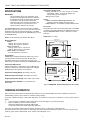
Dimensions: See Fig. 1.
Fig. 1. T8000/T8001 Thermostat dimensions in in. (mm).
M14675
FAN SYSTEM
Auto On
Cool Off Heat
5-1/2 (140)
1-3/16
(55)
3-1/2
(89)
2-3/8
(70)
THERMOSTAT
4-3/8 (111)
WALLPLATE
THERMOSTAT
AND WALLPLATE
3-5/16 (84)
Hold Select
T
U
E
PM

T8000C, T8001C AND T8024D PROGRAMMABLE THERMOSTATS
68-0195–2
3
INSTALLATION
When Installing this Product…
1. Read these instructions carefully. Failure to follow them
could damage the product or cause a hazardous
condition.
2. Check the ratings given in the instructions and on the
product to make sure the product is suitable for your
application.
3. Installer must be a trained, experienced service
technician.
4. After installation is complete, check out product
operation as provided in these instructions.
CAUTION
Damage to Heating/Cooling System Possible.
Be careful when handling wires during installation.
Disconnect power at furnace or main breaker/fuse box.
MERCURY NOTICE
If this control is replacing a control that contains
mercury in a sealed tube, do not place your old
control in the trash. Dispose of it properly.
Contact your local waste management authority for
instructions regarding recycling and the proper
disposal of a control. If you have questions, call the
Honeywell Customer Response Center at 1-800-468-
1502.
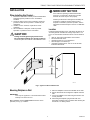
Location
Install the thermostat about 5 ft (1.5m$I above the floor in an
area with good air circulation at average temperature. See
Fig. 2. Do not install the thermostat where it can be affected
by:
— drafts or dead spots behind doors and in corners.
— hot or cold air from ducts.
— radiant heat from the sun or appliances.
— concealed pipes and chimneys.
— unheated (uncooled) areas such as an outside wall
behind the thermostat.
5 FEET
[1.5 METERS]
YES
NO
NO
NO
M11338
Fig. 2. Typical location of thermostat.
Mounting Wallplate to Wall
IMPORTANT
Level only for appearance. The thermostat functions
normally even when not level.
Mount wallplate and the T8000C/T8001C with the screws
provided (see Fig. 3) as follows:
1. Place the wallplate at the desired location on the wall.
2. Pull the thermostat wire through the wallplate entrance
hole.
3. Fasten the wallplate to the wall using the anchors and
screws provided.
4. After wiring the wallplate, plug the hole with non-
flammable insulation to prevent drafts from affecting the
thermostat; see Wiring section.

T8000C, T8001C AND T8024D PROGRAMMABLE THERMOSTATS
68-0195–2
4
M12202
WALL
WALL
ANCHORS (2)
WALLPLATE
MOUNTING
SCREWS (2)
Fig. 3. Mounting wallplate to wall.
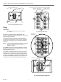
Wiring
IMPORTANT
Use an 18-gauge maximum wire for wiring the
thermostats.
All wiring must comply with local electrical codes and
ordinances. Disconnect the power supply to prevent electrical
shock or equipment damage.
The shape of the terminals permits insertion of straight or
wraparound wiring connections; either method is acceptable.
A letter code is located near each terminal for identification.
See Fig. 4.
NOTE: To ensure proper mounting of thermostat, restrict all
wiring to the shaded area in the center of the
terminals. See Fig. 5.
The T8000C Thermostats are powered through the heating/
cooling system controls and are adaptable to most 18 to 30
Vac heating-cooling systems.
The T8001C and T8024D Thermostats are powered directly
from the system transformer. The T8001C Thermostats are
adaptable to most 18 to 30 Vac single-stage heating/cooling
systems and the T8024D is adaptable to multistage systems.
All T8001C and T8024D thermostats require a common wire
connected to the system transformer to operate properly.
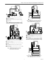
Refer to Fig. 6 through 10 for typical wiring hookups.
KEEP WIRING IN
SHADED AREA
MOUNTING
SCREW HOLE
MOUNTING
SCREW HOLE
WIRING ENTRANCE
HOLE
M18503
G
C
R
Y
W1
W2
B
O
Fig. 8. T8000C wiring diagram in heat-cool
system with two transformers.
TERMINAL
SCREW
M20212
G
R
C
Y
W1
B
O
FOR STRAIGHT
INSERTION STRIP
5/16 IN. (8 MM)
FOR WRAPAROUND
STRIP 7/16 IN. (11 MM)
Y2
W2
Fig. 4. Wiring connections.
Fig. 5. Restrict wiring to shaded area.

T8000C, T8001C AND T8024D PROGRAMMABLE THERMOSTATS
68-0195–2
5
L1
(HOT)
L2
M12561
FAN
RELAY
T8000C THERMOSTAT
COMPRESSOR
CONTACTOR
TRANSFORMER
COOL
DAMPER
1
POWER SUPPLY. PROVIDE DISCONNECT MEANS AND OVERLOAD
PROTECTION AS REQUIRED.
CAN BE USED FOR CHANGEOVER VALVE ON SINGLE-STAGE HEAT
PUMP SYSTEMS.
JUMPER R TO Rc.
2
3
2
2
1
Y
G
Rc
W
3
R
B
O
HEAT
RELAY
HEAT
DAMPER
Fig. 8. T8000C heat-cool wiring diagram on a
zone 1 MABS II Mastertrol control panel.
T8
T7
T6
T5
O1
G1
B1
E1
T4
ZONE 1
CHANGEOVER
CONTROL
M12563
Y
G
Rc
W
1
1JUMPER R TO RC.
R
B
O
T8000C THERMOSTAT
Fig. 9. T8001C heat-cool wiring diagram in single
transformer system with gas heat/electric cooling.
Fig. 6. T8000C heat-cool wiring diagram in single
transformer system with gas heat/electric cooling.
Fig. 7. T8000C wiring diagram in heat/cool
system with two transformers.
Y
G
Rc
W
2
4
R
B
O
M12562
L1
(HOT)
L2
FAN
RELAY
HEAT
RELAY
L1
(HOT)
L2
COMPRESSOR
CONTACTOR
HEATING
TRANSFORMER
COOLING
TRANSFORMER
HEAT
DAMPER
COOL
DAMPER
1
POWER SUPPLY. PROVIDE DISCONNECT MEANS AND OVERLOAD
PROTECTION AS REQUIRED.
REMOVE RC TO R JUMPER WHEN INSTALLED ON A TWO TRANSFORMER
SYSTEM.
CAN BE USED FOR CHANGEOVER VALVE ON SINGLE-STAGE HEAT
PUMP SYSTEMS.
POWER TO R TERMINAL IS REQUIRED WHEN THE SYSTEM SWITCH IS IN
THE OFF POSITION.
2
3
3
1
1
3
4
L1
(HOT)
L2
M12566
FAN
RELAY
HEAT
RELAY
COMPRESSOR
CONTACTOR
TRANSFORMER
HEAT
DAMPER
COOL
DAMPER
1
POWER SUPPLY. PROVIDE DISCONNECT MEANS AND OVERLOAD
PROTECTION AS REQUIRED.
CAN BE USED FOR CHANGEOVER VALVE ON SINGLE-STAGE HEAT
PUMP SYSTEMS.
2
2
2
1
Y
G
C
W
2
R
B
O
T8001 THERMOSTAT
T8
T7
T6
T5
O1
G1
B1
E1
T4
M1
ZONE 1
CHANGEOVER
CONTROL
M12567
Y
G
C
W
R
B
O
T8001 THERMOSTAT
Fig. 10. T8001C heat-cool wiring diagram on a
zone 1 MABS II Mastertrol control panel.

T8000C, T8001C AND T8024D PROGRAMMABLE THERMOSTATS
68-0195–2
6
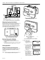
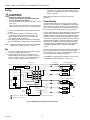
Fig. 11. T8024D multistage heat/cool wiring diagram.
Setting Fan Operation (Fuel) Switch
The fan operation (fuel) switch is preset at the factory in the F
position. See Fig. 11. This is the correct setting for most
systems. If this system is an electric heat system, set the
switch to the E position. The E setting allows the fan to turn
on immediately with the heating or cooling equipment in a
system where the G terminal is connected.
M12580
FAN OPERATION
(
FUEL
)
SWITCH
F
E
Fig. 13. Mounting thermostat to wallplate.
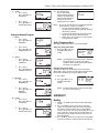
1. Enter Installer Setup.
a. Use ▲ or ▼ keys to set
the temper-ature
setpoint to 52 °F (11°C).
b. Press the ▲ and ▼ keys
simultaneously for more
than two seconds to
enter installer setup.
When released a
software revision code
is displayed.
c. Press the ▲ key.
Factory config-uration
(FC) is displayed (A
typical example is
shown, but information
displayed varies by
model. This information is for factory use only).
M14674
DASHED LINES INDICATE TABS
ON BACK OF THERMOSTAT
ENGAGE TABS AT TOP OF THERMOSTAT
WITH SLOTS ON WALLPLATE.
PRESS LOWER EDGE OF
CASE TO LATCH.
A
B
SYSTEM
Cool Off Heat
Auto On
F
A
N
Hold
Select
SYSTEM
C
ool Off Heat
A
u
to
O
n
FAN
Hold
Select
T
U
E
P
M
M12582A
SET
HT.
M12583A
L1
(HOT)
L2
M20214
FAN
RELAY
STAGE-
ONE
HEAT
RELAY
STAGE ONE
COOLING
TRANSFORMER
HEAT
DAMPER
COOL
DAMPER
1
POWER SUPPLY. PROVIDE DISCONNECT MEANS AND OVERLOAD
PROTECTION AS REQUIRED.
1
Y
G
C
W1
R
B
O
Y2
T8024 THERMOSTAT
W2
STAGE-
TWO
COOL-
ING
STAGE-
TWO
HEAT
RELAY
Fig. 12. Fan operation (fuel) switch.
Mounting Thermostat to Wallplate
1. Slide SYSTEM switch to the Off position.
2. Engage the tabs at the top of the thermostat and
wallplate.
3. Swing down the thermostat and press the lower edge of
the thermostat onto the wallplate to latch. See Fig. 12.
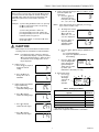
INSTALLER SETUP
Setting °F/°C Indication and Heat Cycle Rate
The following instructions provide the information necessary
to change the heating cycle rate to match the heating
equipment and to choose either Fahrenheit (°F) or Celsius
(°C) display.
NOTE: All four steps must be completed to save changes to
the °F/°C indication and the heat cycle rate.
M12584A

T8000C, T8001C AND T8024D PROGRAMMABLE THERMOSTATS
68-0195–2
7
Optional System Checkout
When in steps 1c and 1d only, pressing the ▼ key can be
used to turn heat or cool outputs on and off. Change the
SYSTEM switch setting to test heat or cool outputs. No
action takes place If the system switch is in the Off
position.
Examples: System setting at HEAT: If heat is on, pressing
the ▼ key turns it off; if heat is off, pressing
the ▼ key turns it on.
System setting at COOL: If cool is on,
pressing the ▼ key turns it off; if cool is off,
pressing the ▼ key turns it on. The five minute
minimum off time is bypassed.
NOTE: For T8024D, a second press ▼ turns
on the 2nd stage.
CAUTION
Allow compressor to remain off for 5 minutes before
restarting. Refer to manufacturer recommendations.
NOTE: In Installer Setup only, each press of the ▲
key momentarily displays 1. Each press of the
▼ key momentarily displays 2. When the keys
are released, these one-digit codes are no
longer displayed.
2. Setting °C or °F.
a. Press the ▲ key again to
display the current
setting.
b. Press the ▼ key to
change the °C or °F
indication.
3. Setting number of heat/cool
stages (T8024 only).
a. Press ▲ to display
number of cooling stages.
b. Press ▼ to change
number of cooling stages.
c. Press ▲ to display
number of heat stages.
d. Press ▼ to change
number of heat stages.
4. Setting 2nd Stage Heat Cycle Rate (see Table 1) for the
cycle rate options and
equipment).
a. Press the ▲ key to
display the current
heat cycle rate setting
of 1, 3, 6, 9, or 12 cph.
NOTE: If the desired cycle rate is displayed, press the ▲
key to exit the installer setup.
b. To change the second
cycle rate, press the
▼ key until your
choice of 1, 3, 4, 5, 6,
9, or 12 is displayed.
c. Press the ▲ key to
display cooling
algorithm configu-
ration default.
d. Press the ▲ key again to change algorithm to C1
or C3.
C1 = Standard algorithm.
C3 = Agressive algorithm (can cause
overshooting).
e. Press the ▲ key again.
Current configuration
(CC) is displayed. A
typical example is
shown, but CC varies
by model. (This
information is for factory use only.)
5. Exit Installer Setup.
a. Press the ▲
key to save
all changes
and return to
normal
operation.
Table 1. Heating Cycle Rates
a
High efficiency furnace (90+).
b
Refer to the equipment manufacturer s Instructions.
M12586A
M12587A
M20215
M20216
M20217
M20218
M12588A
M12589A
M14691
System
Cycles
Per Hour
Steam, Gravity 1
Hydronic Heat, Condensing Gas Furnaces
a
3
Gas or Oil Forced Air 6
Electric Heat 9
Special Applications
b
12
M12590A
PM
M14692

T8000C, T8001C AND T8024D PROGRAMMABLE THERMOSTATS
68-0195–2
8
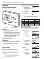
OPERATION
Setting FAN and SYSTEM Switches
Fan and system settings are controlled manually by using the
switches located at the bottom of the thermostat case. See
Fig. 14.
Setting the Current Time and Day
1. To Set Current Time.
a. Press Select twice.
b. Press ▲ or ▼ to set
current time. While setting
the current time, the word
SET is displayed.
2. To Set Day of Week.
a. Press Select again.
b. Press ▲ or ▼ to set
current day.
NOTE: To use the preprogrammed time and temperature
(see Table 2), press Hold to exit Programming.
Table 2. Preprogrammed Time and Temperature Settings.
M12624A
M12625B
M12626A
M12627A
M12628A
M12629A
M12591A
SET
PM
M12593A
SYSTEM
Cool Off Heat
Auto
On
FAN
T8000
M12547
SLEEP
Hold
Select
Fig. 14. Digital Display and System Switches.
FAN Switch
Fan switch settings are:
On: The fan runs continuously. Use for improved air
circulation and air quality.
Auto: Normal setting for most homes. In cooling, the fan
starts and stops with the cooling equipment. In heating,
the fan is controlled directly by the heating equipment
and may start a few minutes after the heating
equipment turns on (most systems). When the fan
operation (fuel) switch is in the E position, the fan starts
and stops with the heating equipment.
Slide the FAN switch in the lower left corner of the thermostat
to select the desired fan setting.
SYSTEM Switch
System switch settings control thermostat operation as follows:
Cool: The thermostat controls the cooling system.
Off: Both heating and cooling are off.
Heat: The thermostat controls the heating system.
Slide the SYSTEM switch in the lower right corner of the
thermostat to select the desired system setting.
PROGRAMMING
The thermostat is flexible and can be programmed for
different schedules for weekdays and weekends.
Four time periods are available during weekdays and
weekends W AKE, LEAVE, RETURN, and SLEEP.
IMPORTANT
Always press the keys with your fingertip or similar
blunt tool. Sharp instruments like pens and pencil
points can damage the keyboard.
Setting the Weekday Program
Slide the SYSTEM switch to the position, heating or cooling,
you want to program. The flame (heating) or the snowflake
(cooling) will appear in the lower right corner of the display.
3. WAKE
a. Press Select.
Press ▲ or ▼ to set
WAKE time.
b. Press Select.
Press ▲ or ▼ to set
WAKE temperature.
4. LEAVE
a. Press Select.
Press ▲ or ▼ to set
LEAVE time.
b. Press Select.
Press ▲ or ▼ to set
LEAVE temperature.
5. RETURN
a. Press Select.
Press ▲ or ▼ to set
RETURN time.
b. Press Select.
Press ▲ or ▼ to set
RETURN
temperature.
Period Time Heat Setpoint Cool
Setpoint
Wake 6:00 AM 70°F (21°C) 78°F (26°C)
Leave 8:00 AM 62°F (17°C) 85°F (29°C)
Return 6:00 PM 70°F (21°C) 78°F (26°C)
Sleep 10:00PM 62°F (17°C) 82°F (28°C)

T8000C, T8001C AND T8024D PROGRAMMABLE THERMOSTATS
68-0195–2
9
6. SLEEP
a. Press Select.
Press ▲ or ▼ to set
SLEEP time.
b. Press Select.
Press ▲ or ▼ to set
SLEEP temperature.
Setting the Weekend Program
7. WAKE
a. Press Select.
Press ▲ or ▼ to set
WAKE time.
b. Press Select.
Press ▲ or ▼ to set
WAKE temperature.
8. LEAVE
a. Press Select.
Press ▲ or ▼ to set
LEAVE time.
b. Press Select.
Press ▲ or ▼ to set
LEAVE temperature.
9. RETRUN
a. Press Select.
Press ▲ or ▼ to set
RETRUN time.
b. Press Select.
Press ▲ or ▼ to set
RETRUN
temperature.
10. SLEEP
a. Press Select.
Press ▲ or ▼ to set
SLEEP time.
b. Press Select.
Press ▲ or ▼ to set
SLEEP temperature.
11. End Programming.
Press Select. End is
displayed. Programming is
complete. The thermostat
will revert to displaying the
current day, time and
temperature in five seconds.
NOTE: To reset the thermostat to the preprogrammed time
and temperature settings (see Table 1):
1. Press and hold the Hold and Select keys
simultaneously. The display will begin counting
down from 36 to zero.
2. The thermostat display will go blank, then will
display the current time and temperature.
3. Release keys, the program has reverted to the
preprogrammed settings.
Setting Temperature Hold
Slide the SYSTEM switch to the heat or cool position.
Temporary Temperature Hold
1. Press ▲ or ▼ key to set a
temporary temperature
setting.
NOTE: The temporary temperature setting is displayed
for approximately 3 seconds. The setting
remains in effect until the next program period.
To cancel, press Hold twice.
Indefinite Temperature Hold
The Hold key allows you to indefinitely hold a temperature.
When Hold is active, the letters Hld are displayed continuously.
Hold can be canceled by pressing the Hold key again.
1. Press Hold
2. Press ▲ or ▼ key to set
indefinite temperature
setting.
NOTE: Indefinite hold remains in effect until the Hold
key is pressed to cancel it.
CHECKOUT
Heating
1. Slide the SYSTEM switch to Heat and the FAN switch
to Auto.
2. Press and hold the ▲ key to raise the temperature
setting several degrees above the room temperature;
the heating equipment should start. In conventional
systems, the system turns on the fan through the use of
a time delay relay or through a limit control. When the
fan operation (fuel) switch is in the E position, the fan
starts immediately.
3. Press the ▼ key to lower the temperature setting below
the room temperature. Heating equipment should stop.
M12630A
M12631B
M12632A
M12633B
M12634A
M12635A
M12640A
TEMPORARY
WED
PM
M12641A
M12636A
M12637A
M12638A
M12639B
M12511A

T8000C, T8001C AND T8024D PROGRAMMABLE THERMOSTATS
68-0195–2
10
L1
(HOT)
L2
1
L1
(HOT)
L2
1
1
2
2
POWER SUPPLY. PROVIDE DISCONNECT MEANS AND OVERLOAD PROTECTION AS REQUIRED.
FACTORY INSTALLED JUMPER.
SYSTEM
SWITCH
FAN
SWITCH
HEAT
OFF
COOL
O
G
RC
B
R
W
Y
FAN RELAY
M11730
THERMOSTAT WALLPLATE SYSTEM COMPONENTS
HEAT RELAY
HEAT CHANGEOVER RELAY
COOL CHANGEOVER RELAY
COMPRESSOR
RELAY
ON
AUTO
POWER
SUPPLY
LOGIC/
CONTROL
CIRCUIT
E
F
FUEL
SWITCH
STAGE 1
HEAT OR
COOL
HEAT 2
MOSFET
MOSFET
Cooling
CAUTION
Damage To Compressor Possible.
Operating at too low of an outdoor temperature
may cause compressor damage.
Do not operate cooling if outdoor temperature is below
50°F (10°C).
Allow compressor to remain off for five minutes before
restarting. Refer to manufacturer’s recommendations.
1. Slide the SYSTEM switch to Cool and the FAN switch
to Auto.
2. Press the ▼ key to lower the temperature setting
several degrees below the room temperature; the
cooling equipment should start. The fan starts and
stops with the cooling equipment.
3. Press the ▲ key to raise the temperature setting above
the room temperature. Cooling system should shut down.
NOTE: To prevent damage to the compressor the T8000C/
T8001C have a built-in off-timer. See page 11.
Fan
1. Slide the SYSTEM switch to Off and the FAN switch to
On. The fan should run continuously.
2. Slide the FAN switch to Auto. In heating, the fan is
controlled directly by the heating equipment and may
start a few minutes after the heating equipment turns
on (most systems). When using an electric heat
thermostat, the fan starts and stops with the heating
equipment. In cooling, the fan starts and stops with the
cooling equipment.
Make certain all equipment responds properly to the
thermostat.
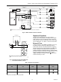
Power Stealing
Unlike hard wired thermostats which are powered directly
from the system transformer, the T8000C Thermostat steals
power through the heating and cooling system controls and
can be used in applications where existing wiring does not
permit using hard wired thermostats. See Fig. 15 and 16.
Previous Honeywell power stealing thermostats required 80 mA
of load current when the heating and cooling was on. The
T8000C Thermostat requires only 2.5 mA of load current (1/32
of previous models) when the heating or cooling is on. When
the heating or cooling is off, the thermostat operates at 0.1 mA
(1/100 of previous models). Other Honeywell power stealing
thermostats are available, but they have different powering
requirements than the T8000C. This low current draw makes
the T8000C applicable to most 24V heating and cooling
systems.
The thermostats only operate when mounted on the wallplate
with 24V applied. Batteries are not required for operation
because temperature setpoints and configuration settings are
retained permanently in nonvolatile memory.
The T8000C is packaged with a 7870 ohm resistor to insure
compatibility with TACO zone valves. See Fig. 17.
Fig. 15. T8000C power stealing internal schematic.

T8000C, T8001C AND T8024D PROGRAMMABLE THERMOSTATS
68-0195–2
11
L1
(HOT)
L2
1
1
POWER SUPPLY. PROVIDE DISCONNECT MEANS AND OVERLOAD PROTECTION AS REQUIRED.
SYSTEM
SWITCH
FAN
SWITCH
HEAT
OFF
COOL
O
G
B
R
W
Y
FAN RELAY
M11731
THERMOSTAT WALLPLATE SYSTEM COMPONENTS
HEAT RELAY
HEAT CHANGEOVER
RELAY
COOL CHANGEOVER
RELAY
COMPRESSOR
RELAY
ON
AUTO
POWER
SUPPLY
LOGIC/
CONTROL
CIRCUIT
EF
FUEL
SWITCH
STAGE 1
HEAT OR
COOL
C
K1
Fig. 16. T8001C hardwired internal schematic.
Fig. 17. Connect resistor to the TACO zone
valve terminal numbers 1 and 2.
FAN Switch Settings SYSTEM Switch Settings Call for Action Energize Terminals Display Icons
Auto Off None None None
On Any Any G None
Auto Cool Cooling G,Y
Auto Heat Heating W,G
a
1
2
3
RESISTOR
L1
(HOT)
L2
1
1
THERMOSTAT
RW
POWER SUPPLY. PROVIDE DISCONNECT MEANS AND
OVERLOAD PROTECTION AS REQUIRED.
TACO ZONE VALVE
M11677
Sequence of Operations
The Fan, Heat and Cool outputs are relay or mosfet
controlled. A loss of ac power or a change in the SYSTEM
switch setting can cause the outputs to turn off. The truth
table shows the sequence of operations for the FAN settings
and SYSTEM modes. See Table 3, Sequence of Operations.
Minimum Off-Timer
A minimum off-timer in the T8000C and T8001D assures that
the compressor does not come on again for at least five
minutes after it turns off. The minimum off-timer is triggered
when the compressor turns off and when the SYSTEM switch
position is changed. If the compressor turns off when the
setpoint is changed, the minimum off-timer is triggered. Power
interruption and power restoration also trigger the minimum off-
timer. The minimum off-timer operates in cooling on the
T8000C and T8001C. A flashing snowflake indicates the
minimum off-timing is in effect.
Table 3. Sequence of Operations.
a
When the Fuel switch is in the E position.

T8000C, T8001C AND T8024D PROGRAMMABLE THERMOSTATS
68-0195–2
2
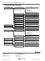
SYMPTOM POSSIBLE CAUSE ACTION
HEATING OR COOLING EQUIPMENT
WON'T OPERATE.
NO AC POWER TO THERMOSTAT.
• CHECK THAT C TERMINAL IS CONNECTED TO
THE SYSTEM TRANSFORMER (T8001 ONLY).
• CHECK POWER TO HEATING AND COOLING EQUIPMENT
– ON/OFF SWITCH
– FUSE OR CIRCUIT BREAKER
– LOOSE 24V CONNECTION
AT THERMOSTAT
AT FURNACE/AIR CONDITIONER
– INCORRECT WIRING (SEE WIRING DIAGRAM)
THERMOSTAT INOPERATIVE. CONDUCT SELF-TEST; SEE CHECKOUT SECTION.
PRESENT SETTING TOO LOW/HIGH. ADJUST TEMPERATURE BY PRESSING OR KEYS.
SYSTEM SWITCH ON THERMOSTAT
IN WRONG POSITION.
RESET THERMOSTAT SYSTEM SWITCH.
MINIMUM/OFF-TIMES IN THERMOSTAT
IN OPERATION ON COOLING.
WAIT FIVE MINUTES OR FOLLOW STEPS IN
CHECKOUT SECTION.
MINIMUM/OFF-TIMES IN THERMOSTAT
IN OPERATION ON COOLING.
WAIT FIVE MINUTES OR FOLLOW STEPS IN
CHECKOUT SECTION.
INCORRECT WIRING.
CHECK WIRING DIAGRAM.
CONSULT EQUIPMENT MANUFACTURER INSTRUCTIONS.
HEATING OR COOLING EQUIPMENT
INOPERATIVE.
REPLACE THERMOSTAT.
PARTIAL DISPLAY
IS FLASHING AND COOLING WILL
NOT OPERATE
INOPERATIVE THERMOSTAT.
SEE THE INSTALLER SETUP SECTION FOR INSTRUCTIONS.
STILL IN INSTALLER SETUP MODE.
RECONFIGURE THE DISPLAY. SEE INSTALLER SETUP
SECTION.
TEMPERATURE DISPLAY IS
INCORRECT.
THERMOSTAT IS CONFIGURED FOR
°F OR °C DISPLAY.
• CHECK THAT C TERMINAL IS CONNECTED TO
THE SYSTEM TRANSFORMER (T8001 ONLY).
• CHECK POWER TO HEATING AND COOLING EQUIPMENT
– ON/OFF SWITCH
– FUSE OR CIRCUIT BREAKER
– LOOSE 24V CONNECTION
AT THERMOSTAT
AT FURNACE/AIR CONDITIONER
– INCORRECT WIRING (SEE WIRING DIAGRAM)
NO DISPLAY
NO POWER TO THERMOSTAT.
SEE INSTALLATION INSTRUCTIONS FOR
CORRECT MOUNTING.
CHECK THE TEMPERATURE SETPOINTS; TEMPERATURE
SETTING RANGE IS 40°F (4°C) TO 99°F (37°C).
THE UPPER OR LOWER
TEMPERATURE LIMITS WERE
REACHED.
THERMOSTAT MOUNTED
INCORRECTLY ON WALLPLATE.
CHECK WIRING DIAGRAM.
FAN DOES NOT OPERATE PROPERLY
IN HEAT OR COOL MODES.
INCORRECT WIRING.
CONSULT EQUIPMENT MANUFACTURER INSTRUCTIONS.
HEATING OR COOLING EQUIPMENT
INOPERATIVE.
TEMPERATURE SETTINGS WILL NOT
CHANGE. (EX: CANNOT SET THE
HEATING HIGHER OR THE
COOLING LOWER).
M11733
TROUBLESHOOTING T8000/T8001
Home and Building Control
Honeywell Limited-Honeywell Limitée
35 Dynamic Drive
Scarborough, Ontario
M1V 4Z9
Home and Building Control
Honeywell
1985 Douglas Drive North
Golden Valley, MN 55422
Printed in U.S.A. on recycled
paper containing at least 10%
post-consumer paper fibers.
www.honeywell.com/yourhome68-0195–2 G.H. Rev. 10-01
-
 1
1
-
 2
2
-
 3
3
-
 4
4
-
 5
5
-
 6
6
-
 7
7
-
 8
8
-
 9
9
-
 10
10
-
 11
11
-
 12
12


Honeywell T8000C User manual
- Category
- Thermostats
- Type
- User manual
Ask a question and I''ll find the answer in the document
Finding information in a document is now easier with AI
Related papers
-
Honeywell T8000C Installation Instructions Manual
-
-
-
-
-
-
-
Honeywell MAGICSTAT_28 Owner's manual
-
-
Other documents
-
Robertshaw 300-204 Technical Application Guide
-
Trane TCONT600AF11MA Installation Instructions Manual
-
Bard 8403-058 User manual
-
ClimateMaster ATM11H03 Install Manual
-
Hunter 42123 User guide
-
-
-
-
-
Lennox X4147 Installation Instructions Manual