Honeywell CHRONOTHERM T8621A User manual
- Category
- Thermostats
- Type
- User manual
This manual is also suitable for

1 68-0058—1
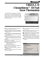
T8621A,C,D
Chronotherm™ III Fuel
Saver Thermostats
C. H. • Rev. 8-92 • ©Honeywell Inc. 1992 • Form Number 68-0058—1
■ Full seven-day program capability; different sched-
ules may be selected for every day.
■ Can be programmed in hand (with batteries in-
stalled) or on wall to provide up to four temperature
settings per day.
■ Large digital clock (liquid crystal display) indi-
cates continuous time, day, current period and
room temperature.
■ Adaptive Intelligent Recovery™ brings room
temperature to programmed temperature at pro-
grammed time, maximizing comfort and energy
savings.
■ Temperature control program maintains tempera-
ture within 1° F of setpoint.
■ Temporary program override available by using—
—WARMER and COOLER keys
—SKIP next period key
—CHANGE to last period key
■ HOLD TEMP key provided for indefinite pro-
gram override (vacation/holiday).
■ Installer self-test and time delay override save
installation time.
■ SYSTEM light-emitting diode (LED) indicates
system is energized.
■ Models available with automatic or manual heat/
cool changeover.
■ Batteries included provide power to maintain
clock and memory during power failures.
■ Switching subbase with wiring terminals included.
■ Powered directly from control transformer, requir-
ing an extra (24V) wire to thermostat.
■ Fan operation switch included on back of SUPER
TRADELINE models to select either indepen-
dent or direct thermostat control of fan in heating.
■ Models available with separate sensor for remote
mounting.
CONTENTS
Specifications ............................................... 2
Ordering Information................................... 2
Selection/Application ................................... 5
Installation ................................................... 7
Checkout..................................................... 17
Programming the Thermostat .................... 19
Operating the Thermostat .......................... 25
Operation ................................................... 28
Troubleshooting ......................................... 29
Glossary ..................................................... 30
Table of Contents ....................................... 31
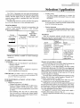
The T8621A,C,D Chronotherm III Program-
mable Fuel Saver Thermostats provide auto-
matic control of single or multistage heating/
cooling systems and offer users the highest
standard of comfort and convenience available
with energy savings.

2
T8621A,C,D
SPECIFICATIONS • ORDERING INFORMATION
Specifications
IMPORTANT: The specifications given in this publica-
tion do not include normal manufacturing toler-
ances. Therefore, this unit may not exactly match
the listed specifications. Also, this product is
tested under closely controlled conditions, and
some minor differences in performance can be
expected if those conditions are changed.
SUPER TRADELINE MODEL
SUPER TRADELINE controls, see Table 1, offer fea-
tures not available on TRADELINE models and are
designed to replace a wide range of Honeywell and
competitive controls.
SUPER TRADELINE FEATURE: Fan operation switch
on back of thermostat to select either independent or
direct thermostat control of fan in heating.
TRADELINE MODELS
TRADELINE models, see Table 2, are selected and pack-
aged to provide ease of stocking and handling and also
maximum replacement value.
LIGHT-EMITTING DIODE (LED): SYSTEM LED
lights during thermostat ON cycle.
VOLTAGE RATING: 15 to 30 Vac.
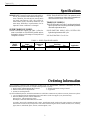
TABLE 1—SUPER TRADELINE MODEL.
Thermostat
Model Stages Changeover Switching
Number Heat Cool Type System Fan Application
T8621D 2 2 Manual HEAT-OFF-COOL ON-AUTO Multistage
Ordering Information
When purchasing replacement and modernization products from your TRADELINE® wholesaler or distributor, refer to the
TRADELINE Catalog or price sheets for complete ordering number, or specify—
1. Model number; SUPER TRADELINE, if desired. 4. Remote temperature sensing, if desired.
2. Number of heat and cool stages desired. 5. Application.
3. System, fan switching desired.
If you have additional questions, need further information or would like to comment on our products or services, please write or phone:
1. Your local Honeywell Home and Building Control Sales Office (check white pages of your phone directory).
2. Home and Building Control Customer Satisfaction
Honeywell Inc., 1885 Douglas Drive North
Minneapolis, Minnesota 55422-4386 (612) 951-1000
In Canada—Honeywell Limited/Honeywell Limitee, 740 Ellesmere Road, Scarborough, Ontario M1P 2V9. International
Sales and Service offices in all principal cities of the world. Manufacturing in Australia, Canada, Finland, France, Germany,
Japan, Mexico, Netherlands, Spain, Taiwan, United Kingdom, U.S.A.

3 68-0058—1
T8621A,C,D
SPECIFICATIONS
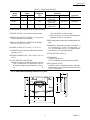
TABLE 2—TRADELINE MODELS.
Thermostat
Model Stages Changeover Switching
Number Heat Cool Type System Fan Application
T8621A* 1 1 Auto HEAT-AUTO- ON-AUTO Single stage
COOL-OFF
T8621C 2 1 Auto HEAT-AUTO- ON-AUTO Multistage
COOL-OFF
T8621D* 2 2 Auto HEAT-AUTO- ON-AUTO Multistage
COOL-OFF
*Model available with separate sensor for remote mounting.
CURRENT RATING: 1.6A maximum total per stage.
OPERATING HUMIDITY RANGE: 5 to 90 percent
relative humidity, noncondensing.
OPERATING AMBIENT TEMPERATURE RANGE:
40° F to 110° F [4° C to 43° C].
SETPOINT RANGE: 45° F to 88° F [7° C to 31° C].
CALIBRATION: Self-calibrating thermostat and ther-
mometer to ±1° F.
SHIPPING TEMPERATURE: -20° F to +120° F [-29° C to
+49° C].
CYCLES PER HOUR ADJUSTMENT:
Heating: First stage of 2-stage heat models—fixed at
3 cph. Second stage of 2-stage heat models or
heat stage of single-stage heat models—factory-
set at
6 cph; adjustable for other systems.
Cooling: Factory-set at 3 cph (not field adjustable);
minimum off-time of five minutes.
FINISH: Beige matte with decorative brushed metal face-
plate.
DIMENSIONS: Thermostat (mounted on subbase)—7
in. [178 mm] long, 5-5/16 in. [135 mm] high, 1-3/
4 in. [44 mm] deep. See Fig. 1 for subbase dimen-
sions and Fig. 2 for sensor dimensions.
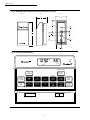
TYPICAL KEYPAD: See Fig. 3.
ACCESSORIES:
TG586A Locking Cover.
TG512 Versaguard Universal Thermostat Guard.
REPLACEMENT PARTS:
202905AA Remote Temperature Sensor Assembly.
Includes sensor, screws, anchors and instructions. See
Fig. 2 for dimensions.
Fig. 1—T8621 Subbase mounting dimensions in in. [mm].
4 [121]
3
4
3 [83]
5
16
7 [179]
1
[46]
13
16
5
[135]
5
16
M5181A
4
3
32
[104]
1
31
32
[50]

4
T8621A,C,D
SPECIFICATIONS • SELECTION/APPLICATION
Fig. 2—202905AA Remote Temperature Sensor dimensions in in. [mm].
4
3
32
[104]
FRONT
1
31
32
[50]
SIDE
M5244
2
[51]
1
31
32
[50]
41
64
[16]
3
8
1
19
64
9
64
1
2
[8]
[4]
DIA.
[13]
[35]
1
[25]
BACK
Fig. 3—Typical thermostat keypad.
SYSTEM
RUN
PROGRAM
PERIOD
TIME
TEMPERATURE
PRESENT
SETTING
SKIP
NEXT
PERIOD
CHANGE
TO LAST
PERIOD
SET
PRESENT
DAY/TIME
HOLD
TEMP
DAY
SET
HEAT/COOL
CANCEL
PERIOD
COPY
FROM
AHEAD
WARMER
BACK COOLER
M5360
WED
MIDDAY
AM
HEAT ON
HEAT OFF
COOL
ON AUTO
FAN
ROOM
COPY
TO


10
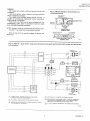
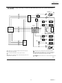
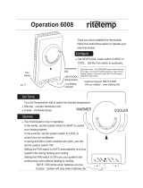
Fig. 9—T8621C 2-stage heat/1-stage cool thermostat with HEAT-AUTO-COOL-OFF system and AUTO-ON
fan switching.
NOMINAL 24 Vac POWER MUST BE PRESENT BETWEEN R AND C FOR
THERMOSTAT OPERATION.
DENOTES THERMOSTAT TO SUBBASE INTERCONNECTION.
M5233
HEATING
TRANSFORMER
R
C
W1
W2
HEAT RELAY 1
HEAT RELAY 2
COOLING
TRANSFORMER
Y1
G
RC
COOLING
CONTACTOR
FAN RELAY
HEAT 1
HIGH
LIMIT
HIGH
LIMIT
L1
(HOT)
L2
HEAT
AUTO
OFF
SYSTEM
SWITCH
AUTO
ON
FAN
SWITCH
COOL
HEAT 2
2
1
COOL
L1
(HOT)
L2
1
2
1
2
3
4
3
4
SUBBASE
LOGIC/
CONTROL
CIRCUIT
POWER SUPPLY. PROVIDE DISCONNECT MEANS AND OVERLOAD
PROTECTION AS REQUIRED.
FOR SINGLE TRANSFORMER SYSTEM JUMPER R AND RC.
POWER
SUPPLY
THERMOSTAT
LOGIC CIRCUIT
T8621A,C,D
INSTALLATION

11 68-0058—1
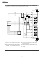
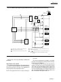
Fig. 10—T8621D 2-stage heat/2-stage cool thermostat with HEAT-AUTO-COOL-OFF system and AUTO-ON
fan switching.
APPLICABLE ONLY ON T8621D MODEL WITH REMOTE SENSOR.
RECOMMENDED INTERCONNECT CABLE: 18-GAUGE THERMOSTAT
CABLE, 200 ft. [61 m] MAXIMUM LENGTH. ROUTE INTERCONNECT
CABLE AWAY FROM SOURCES OF ELECTRICAL NOISE.
DENOTES THERMOSTAT TO SUBBASE INTERCONNECTION.
M1031E
HEATING
TRANSFORMER
R
C
W1
W2
HEAT RELAY 1
HEAT RELAY 2
COOLING
TRANSFORMER
Y2
Y1
G
RC
COOLING
CONTACTOR 1
COOLING
CONTACTOR 2
FAN RELAY
HEAT 1
HIGH
LIMIT
HIGH
LIMIT
L1
(HOT)
L2
HEAT
AUTO
OFF
SYSTEM
SWITCH
AUTO
ON
FAN
SWITCH
COOL
HEAT 2
2
1
COOL 2
COOL 1
L1
(HOT)
L2
1
2
S1
S2
S3
S1
S2
S3
202905 REMOTE
SENSOR
5
1
2
3
4
3
SUBBASE
LOGIC/
CONTROL
CIRCUIT
5
4
6
POWER SUPPLY. PROVIDE DISCONNECT MEANS AND OVERLOAD
PROTECTION AS REQUIRED.
FOR SINGLE TRANSFORMER SYSTEM JUMPER R AND RC.
NOMINAL 24 Vac POWER MUST BE PRESENT BETWEEN R AND C FOR
THERMOSTAT OPERATION.
6
POWER
SUPPLY
THERMOSTAT
LOGIC CIRCUIT
T8621A,C,D
INSTALLATION

12
T8621A,C,D
INSTALLATION
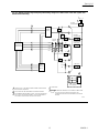
Fig. 11—T8621D 2-stage heat/2-stage cool thermostat with HEAT-OFF-COOL system and AUTO-ON fan
switching; auto fan on heat and cool; convertible to auto fan on cool only.
FOR ELECTRIC HEAT APPLICATIONS (AUTO FAN OPERATES WITH W1
AND Y1). USE ONLY ONE TRANSFORMER; JUMPER R AND RC. SET
SWITCH TO ELECTRIC POSITION.
NOMINAL 24 VAC POWER MUST BE PRESENT BETWEEN R AND C FOR
THERMOSTAT OPERATION.
DENOTES THERMOSTAT TO SUBBASE INTERCONNECTION.
M1016C
HEATING
TRANSFORMER
R
C
W1
W2
B
STAGE 1
HEAT RELAY
STAGE 2
HEAT RELAY
HEATING DAMPER OR
CHANGEOVER RELAY
COOLING
TRANSFORMER
O
Y2
Y1
G
RC
STAGE 1
COOLING RELAY
STAGE 2
COOLING RELAY
COOLING DAMPER OR
CHANGEOVER RELAY
FAN RELAY
HEAT 2
HEAT 1
HIGH
LIMIT
HIGH
LIMIT
L1
(HOT)
L2
HEAT
OFF
COOL
SYSTEM
SWITCH
COOL 1
COOL 2
AUTO
ON
FAN
SWITCH
L1
(HOT)
L2
NON-ELECTRIC
ELECTRIC
FAN
OPERATION
SWITCH
3
2
4
1
3
1
SUBBASE
LOGIC/
CONTROL
CIRCUIT
5
1
2
3
4
5
POWER SUPPLY. PROVIDE DISCONNECT MEANS AND OVERLOAD
PROTECTION AS REQUIRED.
FOR GAS OR OIL APPLICATIONS OR ELECTRIC HEAT APPLICATIONS
WHERE THE FAN OPERATION IS CONTROLLED INDEPENDENTLY OF
THE THERMOSTAT (AUTO FAN OPERATES WITH Y1 ONLY), TWO
TRANSFORMERS MAY BE USED. SET SWITCH TO NON-ELECTRIC
POSITION.
POWER
SUPPLY
THERMOSTAT
LOGIC CIRCUIT

13 68-0058—1
T8621A,C,D
INSTALLATION
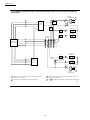
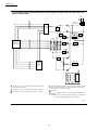
Fig. 12—T8621C,D single stage heat pump with heating changeover. HEAT-AUTO-COOL-OFF system and
AUTO-ON fan switching.
M1547C
SYSTEM
TRANSFORMER
R
C
W1
W2
Y2
Y1
G
RC
FAN RELAY
HIGH
LIMIT
HIGH
LIMIT
L1
(HOT)
L2
HEAT
AUTO
COOL
SYSTEM
SWITCH
AUTO
ON
FAN
SWITCH
T8621D ONLY.
DENOTES THERMOSTAT TO SUBBASE CONNECTIONS.
NOTE: SET CYCLE RATE TO HOT WATER SETTING (3 cph).
THERMOSTAT DOES NOT PROVIDE MINIMUM OFF TIME IN
HEATING.
1
S1
S2
S3
S1
S2
S3
202905 REMOTE
SENSOR
3
OFF
COMPRESSOR
CONTACTOR
HEATING
CHANGEOVER
H1
H2
C1
C2
1
2
5
SUBBASE
LOGIC/
CONTROL
CIRCUIT
POWER SUPPLY. PROVIDE DISCONNECT MEANS AND OVERLOAD
PROTECTION AS REQUIRED.
APPLICABLE ONLY ON T8621 MODEL WITH REMOTE SENSOR.
RECOMMENDED INTERCONNECT CABLE: 18-GAUGE THERMOSTAT
CABLE, 200 ft. [61 m] MAXIMUM LENGTH. ROUTE INTERCONNECT
CABLE AWAY FROM SOURCES OF ELECTRICAL NOISE.
3
4
5
4
2
POWER
SUPPLY
THERMOSTAT
LOGIC CIRCUIT

14
T8621A,C,D
INSTALLATION
Fig. 13—T8621C,D single stage heat pump with cooling changeover. HEAT-AUTO-COOL-OFF system and
AUTO-ON fan switching.
4
5
6
RECOMMENDED INTERCONNECT CABLE: 18-GAUGE THERMOSTAT CABLE,
200 ft. [61 m] MAXIMUM LENGTH. ROUTE INTERCONNECT CABLE AWAY
FROM SOURCES OF ELECTRICAL NOISE.
T8621D ONLY.
DENOTES THERMOSTAT TO SUBBASE INTERCONNECTION.
NOTE: SET CYCLE RATE TO HOT WATER SETTING (3 cph). THERMOSTAT
DOES NOT PROVIDE MINIMUM OFF TIME IN HEATING.
M1548C
SYSTEM
TRANSFORMER
R
C
W1
W2
Y2
Y1
G
RC
FAN RELAY
HIGH
LIMIT
HIGH
LIMIT
L1
(HOT)
L2
HEAT
AUTO
COOL
SYSTEM
SWITCH
AUTO
ON
FAN
SWITCH
1
S1
S2
S3
S1
S2
S3
202905 REMOTE
SENSOR
3
OFF
COMPRESSOR
CONTACTOR
COOLING
CHANGE-
OVER
H1
H2
C1
C2
RELAY K
K
SUBBASE
LOGIC/
CONTROL
CIRCUIT
6
4
5
POWER SUPPLY. PROVIDE DISCONNECT MEANS AND OVERLOAD
PROTECTION AS REQUIRED.
ADD RELAY (SPDT) TO ACCOMMODATE COOLING CHANGEOVER.
APPLICABLE ONLY ON T8621D MODELS WITH REMOTE SENSOR.
1
2
3
POWER
SUPPLY
THERMOSTAT
LOGIC CIRCUIT

15 68-0058—1
T8621A,C,D
INSTALLATION
Fig. 14—T8621D single stage heat pump. HEAT-OFF-COOL system and AUTO-ON fan switching.
M1546
A
SYSTEM
TRANSFORMER
R
C
W1
W2
B
HEATING
CHANGEOVER
RELAY
O
Y2
Y1
G
RC
COMPRESSOR
CONTACTOR
COOLING
CHANGEOVER
RELAY
FAN RELAY
HEAT 2
HEAT 1
HIGH
LIMIT
HIGH
LIMIT
L1
(HOT)
L2
HEAT
OFF
COOL
SYSTEM
SWITCH
COOL 1 COOL 2
AUTO
ON
FAN
SWITCH
NON-ELECTRIC
ELECTRIC
POWER SUPPLY. PROVIDE DISCONNECT MEANS AND
OVERLOAD PROTECTION AS REQUIRED.
FAN OPERATION SWITCH MAY BE IN EITHER POSITION.
1
2
NOMINAL 24 VAC POWER MUST BE PRESENT BETWEEN R AND C FOR
THERMOSTAT OPERATION.
DENOTES THERMOSTAT TO SUBBASE INTERCONNECTION.
NOTE: THERMOSTAT DOES NOT PROVIDE MINIMUM OFF TIME IN
HEATING.
FAN
OPERATION
SWITCH
2
3
1
SUBBASE
LOGIC/
CONTROL
CIRCUIT
4
3
4
POWER
SUPPLY
THERMOSTAT
LOGIC CIRCUIT
Refer to Figs. 8-14 for typical hookups of subbase and
thermostat.
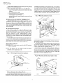
ADJUSTING CYCLE RATE
To customize the thermostat cycling performance to
various types of heating equipment, cycle rate adjustment
screws are provided on the back of the thermostat to
provide optimum room temperature control.
NOTE: Most applications will not require a change in
cycle rate.
The room air temperature will normally vary slightly
from the comfort temperature setting with the cycling of
the fur-nace or air conditioner.
The cooling cycle rate is factory-set and cannot be
adjusted. The heating cycle rate can be adjusted by turning
one or both cycle rate adjustment screws located on the
back of the thermostat. In multistage heat systems, the
cycle rate adjustment applies to the highest stage of heat
only. Screws should be backed out about one-half to one
turn, or be turned in until tight. See Fig. 15.


17 68-0058—1
T8621A,C,D
INSTALLATION • CHECKOUT
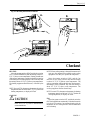
Fig. 17—Mounting thermostat on subbase.
M 843
PM
MORNIMG
MON
HEAT ON
ROOM
SYSTEM
A
U
T
O
P
M
M
O
R
N
IM
G
M
O
N
H
E
A
T
O
N
R
O
O
M
SYSTEM
RUN
PROGRAM
TIME
TEMPERATURE
PRESENT
SETTING
SKIP
NEXT
PERIOD
CHANGE
TO LAST
PERIOD
SET
PRESENT
DAY/TIME
HOLD
TEMP
DAY
SET
HEAT/COOL
CANCEL
PERIOD
COPY
FROM
AHEAD
WARMER
COPY
TO
BACK COOLER
PERIOD
A.
B.
C.
H
E
A
T
A
U
T
O
C
O
O
L
O
F
F
O
N
AU
T
O
F
A
N
HEATING
Move the system switch to HEAT and the fan switch to
AUTO. Press WARMER key until the setting is about 10°
F [6° C] above room temperature. Heating should start
(both stages if multistage), and the fan should run (may be
a short delay on forced air systems). Press cooler key until
the setting is about 10° F [6° C] below room temperature.
The heating equipment should shut off, followed by the
fan.
NOTE: On an AUTO changeover thermostat, the cooling
temperature must be set at least 3° F [2° C] above the
heating temperature, or display will flash.
COOLING
CAUTION
Do not operate cooling if outdoor temperature is
below 50° F [10° C]. Refer to manufacturer’s
recommendations.
NOTE: When cooling setting is changed, thermostat will
wait up to five minutes before turning on the cooling
equipment. This delay is to protect the compressor.
Move the system switch to COOL and the fan
switch to AUTO. Press COOLER key until the setting
is about 10° F [6° C] Below room temperature. The
cooling equipment and fan should start (both stages if
multistage). Press WARMER key until the setting is
about 10° F [6° C] above room temperature. The
cooling equipment and fan should stop.
NOTE: On an AUTO changeover thermostat, the heating
temperature must be set at least 3° F [2° C] below the
cooling temperature, or display will flash.
FAN
Move the system switch to OFF, and the fan switch to
ON. The fan should run continuously. When the fan switch
is in the AUTO position, fan operates directly with the
thermostat call for cooling and also with the thermostat
call for heating.
Checkout
!

18
System Press Look For This Response
Switch This Key
Position Key Down Key Released
OFF 06 Blank
02 Blank
05 Blank
04 Blank
01 Blank
00 Blank
(CHECK 12 See note A .
EACH
POSITION)
OFF 08 Blank
13 Microprocessor mask
no. and revision no.
09 Blank
14 Blank
HEAT or 14 1st stage heating and
AUTO SYSTEM LED on.
14 2nd stage heating
also on.
14 2nd stage heating off.
14 1st stage heating and
SYSTEM LED off.
NOTE: If single-stage heating system, press key twice
instead of 4 times; once to turn heating and SYSTEM
LED on, second time to turn off.
OFF 10 Blank
11 Normal operating
display.
END SELF-TEST
1 For electric heat fan operation—The fan will operate
with the heating system when fan switch is in AUTO.
A HEAT displayed when system switch is in HEAT,
COOL when in COOL, HEAT and COOL when in
AUTO, neither when in OFF. Also, a four-digit code
is displayed, with each digit explained below.
T8621A,C,D
CHECKOUT
INSTALLER SELF-TEST (OPTIONAL)
IMPORTANT:
1. Thermostat must have ac power to perform self-
test. Relays will not toggle, codes will not be
present and thermostat will not manually exit
self-test without ac power.
2. Five-minute time delay on cooling does not function
during self-test.
Perform the following test as a check of all thermostat
functions. If thermostat does not respond as indicated,
thermostat must be replaced.
1. Press AHEAD and BACK keys at the same time.
While holding keys down, all segments of the display
should be on (see Fig. 18).
Fig. 18—All segments on display.
WARME
R
2. Set the system switch to OFF. Press and release
AHEAD and BACK and PRESENT SETTING keys at the
same time to enter self-test.
3. Press each key as listed below, and look for re-
sponses listed as key is held down and released.
System Press Look For This Response
Switch This Key
Position Key Down Key Released
OFF 03 Blank
07 Blank
15 Blank
COOL or 15 1st stage cooling,
AUTO fan and SYSTEM
LED on.
15 2nd stage cooling
also on.
15 2nd stage cooling
off.
15 1st stage cooling,
fan and SYSTEM
LED off.
NOTE: If single-stage cooling system, press key twice
instead of 4 times; once to turn cooling, fan and SYS-
TEM LED on, second time to turn off.
(with fan
in AUTO)
M 525A
AM
SUN
MORNING
REPL
BAT
SET
PT
ROOM
PM
OUTDOOR
TUE WED THU FRI SAT TEMPORARY
MON
MIDDAY EVENING NIGHT COOL ON HEAT ON
1
RUN
PROGRAM
CHANGE
TO LAST
PERIOD
PRESENT
SETTING
PRESENT
SETTING
AHEAD
COOLE
R
BACK
COPY
FROM
COPY
TO
PERIOD
CANCEL
PERIOD
DAY
SET
HEAT/COOL
SET
PRESENT
DAY/TIME
SET
PRESENT
DAY/TIME
SET
PRESENT
DAY/TIME
HOLD
TEMP
SET
PRESENT
DAY/TIME
SET
PRESENT
DAY/TIME
SKIP
NEXT
PERIOD
PRESENT
SETTING
PRESENT
SETTING
PRESENT
SETTING

19 68-0058—1
T8621A,C,D
CHECKOUT • PROGRAMMING THE THERMOSTAT
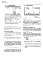
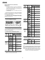
Cycle Rate Setting
(cph at 50% on time for stage
First 1 on 1-heat models, stage
Digit 2 on 2-heat models)
01
13
29
36
Third Manual or Auto System Switch
Digit Changeover Position
0 Manual HEAT or OFF
1 Auto HEAT or OFF
3 Auto AUTO
4 Manual COOL
5 Auto COOL
Second Stages of
Digit Heat Cool
02 1
12 2
21 1
31 2
40 2
51 0
62 0
Fourth Clock System Switch
Digit Degrees (hrs) Position
0 F 12 COOL, AUTO
or OFF
1 F 24 COOL, AUTO
or OFF
2 F 12 HEAT
3 F 24 HEAT
4 C 12 COOL, AUTO
or OFF
5 C 24 COOL, AUTO
or OFF
6 C 12 HEAT
7 C 24 HEAT
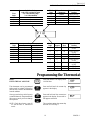
Programming the Thermostat
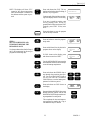
STEP 1
ENTER THE DAY AND TIME
This thermostat can be programmed
either on wall or in hand. See page 8 to
find out how to remove the thermostat
from the subbase.
Always press the keys with fingertip
or similar blunt tool. Sharp instruments
like a pen or pencil point can damage
the keyboard.
NOTE: Check the glossary, page 30
for definitions of unfamiliar
words.
Press and release. The display shows
1:00 PM Mon.
Press and hold until the current day
appears in the display.
Press and hold until the current time
appears in the display. Be sure AM or
PM appears as desired.
This completes setting the current day
and time. Go on to Step 2.
PM
TUE
PM
MON
PM
TUE
DAY
TIME
AHEAD
BACK
SET
PRESENT
DAY/TIME

20
T8621A,C,D
PROGRAMMING THE THERMOSTAT
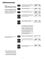
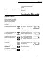
STEP 2
SET THE PROGRAM TIMES AND
TEMPERATURES FOR ONE DAY
Choose a day to program first. Monday
is used in the examples. Start by pro-
gramming the MORNING time and
temperatures. The thermostat requires
a MORNING program every day. Set
additional programs as desired.
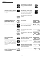
Program the MIDDAY time and heat-
ing temperature if desired.
NOTE: It is possible to cancel any pe-
riod showing on the display except
MORNING by pushing the CAN-
CEL PERIOD key. To move to the
next period while programming,
simply press the PERIOD key again.
Press and release. Note that the display
shows MORNING and the preprogram-
med time and temperature.
If the display reads COOL, press and
release to switch to HEAT.
Press and hold until MONDAY (or the
desired day) appears in the display.
Press and hold until the display shows
the time that the temperature should be
at the comfort setting.
Press and hold until the display shows
the desired heating temperature.
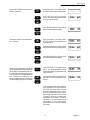
If the display flashes while holding
down TEMPERATURE WARMER or
COOLER, the setting limit has been
reached. If thermostat is an auto-
changeover model, the heating tempera-
ture must be at least 3 degrees below the
air conditioning temperature. For ex-
ample, if the cooling setting is 75° F, the
maximum heating setting is 72° F. To
set a higher heating temperature, first
raise the cooling setting.
Press and release. The display shows
MIDDAY, but no time or temperature.
Press and hold until the display shows
the time to start the energy saving pe-
riod.
Press and hold until the display shows
the desired temperature.
SET
PT
MON
TUE WED THU FRI
HEAT
MORNING
AM
SET
PT
MON
TUE WED THU FRI
HEAT
MORNING
AM
SET
PT
MON
TUE WED THU FRI
HEAT
MORNING
AM
SET
PT
MON
TUE WED THU FRI
HEAT
MORNING
AM
SET
PT
MON
TUE WED THU FRI
HEAT
MORNING
AM
PERIOD
DAY
SET
HEAT/COOL
AHEAD
BACK
WARMER
COOLER
SET
PT
MON
TUE WED THU FRI
HEAT
DAYTIME
SET
PT
MON
TUE WED THU FRI
HEAT
DAYTIME
AM
SET
PT
MON
TUE WED THU FRI
HEAT
DAYTIME
AM
MIDDAY
MIDDAY
MIDDAY
AHEAD
BACK
PERIOD
WARMER
COOLER
Page is loading ...
Page is loading ...
Page is loading ...
Page is loading ...
Page is loading ...
Page is loading ...
Page is loading ...
Page is loading ...
Page is loading ...
Page is loading ...
Page is loading ...
Page is loading ...
-
 1
1
-
 2
2
-
 3
3
-
 4
4
-
 5
5
-
 6
6
-
 7
7
-
 8
8
-
 9
9
-
 10
10
-
 11
11
-
 12
12
-
 13
13
-
 14
14
-
 15
15
-
 16
16
-
 17
17
-
 18
18
-
 19
19
-
 20
20
-
 21
21
-
 22
22
-
 23
23
-
 24
24
-
 25
25
-
 26
26
-
 27
27
-
 28
28
-
 29
29
-
 30
30
-
 31
31
-
 32
32


Honeywell CHRONOTHERM T8621A User manual
- Category
- Thermostats
- Type
- User manual
- This manual is also suitable for
Ask a question and I''ll find the answer in the document
Finding information in a document is now easier with AI
Related papers
-
Honeywell T8621D User manual
-
-
-
-
-
-
-
Honeywell CO810PM Installation guide
-
-
Other documents
-
GE 46707 User manual
-
American Standard TCONT401AN21MA Comfort Control Installer's Manual
-
-
 RiteTemp 6008 Operating instructions
-
American Standard ACONT800 Series Owner's manual
-
White Rodgers 1F95-71 Specification
-
Bryant TSTATBBPS701 User manual
-
-
Panasonic CZ01ESW11P Operating instructions
-
Lennox ComfortSense5000 User manual
