Page is loading ...

-2-
THIS TANK, LIKE MOST TANKS UNDER PRESSURE, WILL OVER TIME CORRODE OR FAIL AND/OR MAY BURST AND/OR LEAK OR
FLOOD (AND IN RARE CASES EXPLODE) WHICH CAN CAUSE SERIOUS OR FATAL PERSONAL INJURY AND PROPERTY DAMAGE.
TO MINIMIZE RISK, A LICENSED PROFESSIONAL MUST INSTALL AND PERIODICALLY INSPECT AND SERVICE THE UNIT. A DRIP PAN, CONNECTED TO AN
ADEQUATE DRAIN MUST BE INSTALLED IF LEAKING OR FLOODING CAN CAUSE PROPERTY DAMAGE.
READ CAREFULLY THE PRODUCT INSTALLATION, OPERATING AND MAINTENANCE MANUAL. FAILURE TO
FOLLOW THE INSTRUCTIONS AND WARNINGS IN THE MANUAL MAY RESULT IN SERIOUS OR FATAL INJURY AND/
OR PROPERTY DAMAGE, AND WILL VOID THE PRODUCT WARRANTY. THIS PRODUCT MUST BE INSTALLED BY A QUALIFIED
PROFESSIONAL. FOLLOW ALL APPLICABLE LOCAL AND STATE CODES AND REGULATIONS, IN THE ABSENCE OF SUCH CODES,
FOLLOW THE CURRENT EDITIONS OF THE NATIONAL PLUMBING CODE AND NATIONAL ELECTRIC CODE, AS APPLICABLE.
AS IN ALL PLUMBING PRODUCTS AND WATER STORAGE VESSELS, BACTERIA CAN GROW IN YOUR WELL TANK,
ESPECIALLY DURING TIMES OF NON-USE. CONSULT YOUR LOCAL PLUMBING OFFICIAL REGARDING ANY STEPS
YOU MAY WISH TO TAKE TO SAFELY DISINFECT YOUR HOME’S PLUMBING SYSTEM.
FOLLOW ALL OF THE INSTRUCTIONS AND RECOMMENDATIONS CONTAINED IN THIS MANUAL, AND THE
FOLLOWING ADDITIONAL SPECIFIC WARNINGS. FAILURE TO DO SO IS UNSAFE AND CAN CAUSE SERIOUS
EXPLOSION, SERIOUS OR FATAL PERSONAL INJURY AND PROPERTY DAMAGE.
EXPLOSION OR RUPTURE HAZARD. THE WELL TANK MUST BE OPERATED SO THAT THE MAXIMUM SYSTEM
PRESSURE DOES NOT EXCEED 150 PSI OR LOCAL CODE REQUIREMENTS WHICHEVER IS LESS.
A RELIEF VALVE WITH A MAXIMUM RELIEF PRESSURE OF 125 PSI MUST BE INSTALLED IN THE SYSTEM. THE
RELIEF VALVE MUST BE CAPABLE OF DISCHARGING THE RATED CAPACITY OF THE PUMP AT THE MAXIMUM
SYSTEM PRESSURE.
FAILURE TO UTILIZE A PROPERLY SIZED WELL TANK (BASED ON THE FOLLOWING SIZING INSTRUCTIONS) WILL
RESULT IN EXCESSIVE STRAIN ON THE PUMP AND MAY ULTIMATELY LEAD TO PRODUCT FAILURE, LEAKING OR
FLOODING AND PROPERTY DAMAGE.
DANGER! EXPLOSION HAZARD. IF YOU ADJUST THE PRE-CHARGE PRESSURE OR ADD PRESSURE TO A TANK
THAT IS CORRODED OR DAMAGED OR WITH DIMINISHED INTEGRITY THE TANK CAN BURST OR EXPLODE,
POSSIBLY CAUSING SERIOUS OR FATAL PERSONAL INJURY AND/OR PROPERTY DAMAGE.
• ONLY ADJUST THE PRE-CHARGE AS DESCRIBED IN THIS MANUAL WHEN THE TANK IS NEW OR WHEN THE
INTEGRITY OF THE TANK AND LACK OF INTERNAL OR EXTERNAL CORROSION IS CONFIRMED.
• ONLY QUALIFIED PROFESSIONALS SHOULD CHECK, ADJUST OR RE-CHARGE THE PRE-CHARGE OF TANKS.
DANGER! EXPLOSION HAZARD. WHEN THE WELL TANK HAS BEEN IN SERVICE AND A CHANGE TO A HIGHER
PRE-CHARGE PRESSURE IS NECESSARY DUE TO A REQUIRED CHANGE IN THE PRESSURE SWITCH SETTING,
FAILURE TO FOLLOW INSTRUCTIONS BELOW CAN CAUSE A RUPTURE OR EXPLOSION, POSSIBLY CAUSING SERIOUS OR FATAL
PERSONAL INJURY, AND/OR PROPERTY DAMAGE. DO NOT ADJUST OR ADD PRESSURE IF THERE HAS BEEN A LOSS OF AIR. DO NOT
ADJUST THE PRE-CHARGE PRESSURE IF THERE IS VISIBLE EXTERIOR CORROSION. DO NOT ADJUST THE PRE-CHARGE PRESSURE
IF THERE HAS BEEN A REDUCTION OF THE PUMP CYCLE TIME OR THE PRE-CHARGE PRESSURE COMPARED TO ITS INITIAL SETTING.
THIS IS BECAUSE REDUCTION IN PUMP CYCLE TIME CAN RESULT FROM LOSS OF TANK AIR PRESSURE WHICH IN TURN CAN MEAN
THERE MAY BE INTERNAL CORROSION AND ANY RE-PRESSURIZATION OR ADDITIONAL PRESSURE COULD RESULT IN RUPTURE OR
EXPLOSION.
CHLORINE & AGGRESSIvE WATER: THE WATER QUALITY CAN SIGNIFICANTLY INFLUENCE THE LIFE OF THIS
PRODUCT. YOU SHOULD TEST FOR CORROSIVE ELEMENTS, ACIDITY, TOTAL SOLIDS AND OTHER RELEVANT
CONTAMINANTS, INCLUDING CHLORINE AND TREAT YOUR WATER APPROPRIATELY TO INSURE SATISFACTORY PERFORMANCE
AND PREVENT PREMATURE FAILURE. FOR YOUR SAFETY, THE INFORMATION IN THIS MANUAL MUST BE FOLLOWED TO MINIMIZE
THE RISK OF ELECTRIC SHOCK, PROPERTY DAMAGE OR PERSONAL INJURY. PROPERLY GROUND TO CONFORM WITH ALL
GOVERNING CODES AND ORDINANCES.
INSTALL OR STORE WHERE TANK WILL NOT BE EXPOSED TO TEMPERATURES BELOW FREEZING OR ABOVE
100ºF. WATER FREEZING IN THE SYSTEM WILL BREAK IT. DO NOT ATTEMPT TO TREAT WATER OVER 100°F.
USE ONLY LEAD-FREE SOLDER AND FLUX FOR ALL SWEAT-SOLDER CONNECTIONS, AS REQUIRED BY STATE
AND FEDERAL CODES.
NOTE: INSPECT FOR SHIPPING DAMAGE AND NOTIFY FREIGHT CARRIER OR STORE WHERE PURCHASED IMMEDIATELY IF DAMAGE
IS PRESENT. TO AVOID RISK OF PERSONAL INJURY AND PROPERTY DAMAGE, IF THE PRODUCT APPEARS TO BE MALFUNCTIONING
OR SHOWS SIGNS OF CORROSION, CALL A QUALIFIED PROFESSIONAL IMMEDIATELY. CURRENT COPIES OF THE PRODUCT MANUAL
CAN BE VIEWED AT WWW.AMTROL.COM. USE PROPER SAFETY EQUIPMENT WHEN INSTALLING.
FAILURE TO FOLLOW THE ABOVE WARNINGS MAY RESULT IN SERIOUS OR FATAL PERSONAL INJURY OR DEATH AND/
OR PERSONAL PROPERTY DAMAGE, AND WILL VOID THE WARRANTY.
1. GENERAL SAFETY INFORMATION

-3-
AMTROL Inc. • 1400 Division Road • W. Warwick, Rhode Island 02893 • Telephone 401-884-6300 • Fax 401-885-2567
The AMTROL logo, AMTROL, Well-X-Trol, Champion, Wel-Flo, Extrol, Fill-Trol, Therm-X-Trol, Value Well and BoilerMate are registered trademarks of AMTROL Inc. and its affiliates in the U.S. and
elsewhere. All rights reserved.
2. LIMITED WARRANTY
Products covered: all Products manufactured by AMTROL Inc. (“AMTROL”) .
This warranty cannot be transferred – it is extended only to the original Purchaser or First User of the Product. By accepting and keeping this Product
you agree to all of the warranty terms and limitations of liability described below.
IMPORTANT WARNING – READ CAREFULLY THE INSTALLATION, OPERATING AND MAINTENANCE INSTRUCTIONS MANUAL (“MANUAL”) to
avoid serious personal injury and/or property damage and to ensure safe use and proper care of this product
Who Receives AMTROL’s Product Warranty
All purchasers or first users of the new Product. The Warranty is non-transferable.
What is covered by this Warranty
AMTROL warrants to the purchaser or first user of the new Product that at the time of manufacture, the Product is free from defects in material and
workmanship. Any warranty claim must be made within one (1) year unless another time period is set forth in the Manual, measured from
the time the Product was purchased.
What AMTROL Will Do If You Have a Covered Warranty Claim
In the event of a breach of the foregoing warranty, AMTROL will at its option either make repairs to correct any defect in material or workmanship or
supply and ship either new or used replacement parts or products. AMTROL will not accept any claims for labor or other costs.
What This Warranty Does Not Cover - Exclusions and Limitations
This Warranty does not cover any failure or problem unless it was caused by a defect in material or workmanship. In addition, this Warranty shall not
apply:
• if the Product is not correctly installed, operated, repaired or maintained as described in the Manual provided with the Product;
• to any failure or malfunction resulting from abuse (including freezing); improper or negligent: handling, shipping (by anyone other than AMTROL),
storage, use, operation, accident; or alteration, lightning, flood or any other environmental condition;
• to any failure or problem resulting from the use of the Product for any purpose other than those specified in the accompanying Manual or alteration
of any part of the product;
• this Warranty does not cover labor costs, shipping charges, service charges, delivery expenses, administrative fees or any costs incurred in
removing or reinstalling the Product;
• this Warranty does not cover any claims submitted to AMTROL or an AMTROL-authorized distributor or retailer more than 30 days after expiration
of the applicable warranty time period described in this Warranty;
• this Warranty also does not cover repair or replacement costs not authorized in advance by AMTROL.
Additional Warranty Limitations
ALL IMPLIED WARRANTIES, INCLUDING THE IMPLIED WARRANTIES OF MERCHANTABILITY AND FITNESS FOR A PARTICULAR
PURPOSE ARE SPECIFICALLY DISCLAIMED.
Limitations of Remedies
THE REMEDIES CONTAINED IN THIS WARRANTY ARE THE PURCHASER’S OR FIRST USER’S EXCLUSIVE REMEDIES. IN NO
CIRCUMSTANCES WILL AMTROL BE LIABLE FOR MORE THAN, AND PURCHASER-FIRST USER’S REMEDIES SHALL NOT EXCEED, THE
PRICE PAID FOR THE PRODUCT. IN NO CASE SHALL AMTROL BE LIABLE FOR ANY SPECIAL, INDIRECT, INCIDENTAL OR CONSEQUENTIAL
DAMAGES, WHETHER RESULTING FROM NON-DELIVERY OR FROM THE USE, MISUSE, OR INABILITY TO USE THE PRODUCT OR FROM
DEFECTS IN THE PRODUCT OR FROM AMTROL’S OWN NEGLIGENCE OR OTHER TORT. This exclusion applies regardless of whether such
damages are sought for breach of warranty, breach of contract, negligence, strict liability, in tort or under any other legal theory. Such damages include,
but are not limited to, inconvenience, loss or damage to property, mold, loss of profits, loss of savings or revenue, loss of use of the Products or any
associated equipment, facilities, buildings or services, downtime, and the claims of third parties including customers.
What To Do If You Have a Problem Covered By This Warranty
Any covered Warranty service must be authorized by AMTROL. Contact the person from whom you purchased the Product, who must
receive authorization from an AMTROL distributor or AMTROL. If you do not receive a prompt response, call AMTROL directly at
877-517-9673. Notice of a Warranty claim should be submitted by the authorized distributor to AMTROL at the following address:
AMTROL Inc., Warranty Claim Dept.
1400 Division Road, West Warwick, RI 02893
Before AMTROL determines to provide any replacement part or Product, it may as a pre-condition to making such a determination require that the
warranty claimant ship the Product, postage prepaid to an authorized AMTROL distributor, or to AMTROL and provide proof of purchase evidenced
by the original sales receipt or Product registration.
Replacement Product Warranty
In case of replacement of a Product or any component part, AMTROL reserves the right to make changes in the design, construction, or material of the
substitute components or products, which shall be subject to all of the terms and limitations of this Warranty, except that the applicable warranty periods
shall be reduced by the amount of time the warranty claimant owned the product prior to submitting notification of the warranty claim.
Revised 01/11

3. PRE-INSTALLATION CHECKLIST
IMPORTANT STEPS AND DECISIONS
REQUIRED BEFORE INSTALLATION
4. REQUIRED COMPONENTS AND
ACCESSORIES CHECKLIST
j
THIS PRODUCT MUST BE INSTALLED AND
MAINTAINED BY A LICENSED PROFESSIONAL. IN
ADDITION TO THE INSTRUCTIONS IN THIS MANUAL,
FOLLOW ALL APPLICABLE LOCAL AND STATE
CODES OR IN THE ABSENCE OF SUCH CODES, THE
CURRENT EDITIONS OF THE NATIONAL PLUMBING
CODE AND THE NATIONAL ELECTRIC CODE.
j
DRIP PAN AND DRAIN: To avoid leaking and/or flooding
damage, install with a drip pan connected to an adequate
working drain kept clear at all times.
j
1. PRESSURE SWITCH
j
2. RELIEF VALVE
j
3. 1 UNION
j
4. 1 SHUT OFF VALVE
j
5. VALVE DRAIN
j
6. PRESSURE GAUGE
j
7. TANK-TEE
VERTICAL STAND MODELS
MAXIMUM WORKING PRESSURES
Every well tank is air tested to 100 psig,
the maximum working pressure for the well tank line.
RELIEF VALVE RECOMMENDED
It is recommended that a relief valve
be installed which is set to open at excessive pressures (75
psig or more). This will protect your well tank and other system
components should the pressure switch malfunction and fail to
shut the pump off. The relief valve should be installed at the
connection of your well tank to the system piping and have a
discharge equal to the pump’s capacity at 75 psig.
5. INSTALLATION INSTRUCTIONS
Location
Proper well tank Location
The well tank should be installed as close as possible to the
pressure switch. This will reduce the adverse effects of added
friction loss and pressure switch bouncing, and the difference in
elevation between well tank and switch.
DANGER! EXPLOSION HAZARD. WHEN THE WELL
TANK HAS BEEN IN SERVICE AND A CHANGE TO
A HIGHER PRE-CHARGE PRESSURE IS NECESSARY DUE TO A REQUIRED
CHANGE IN THE PRESSURE SWITCH SETTING, FAILURE TO FOLLOW
INSTRUCTIONS BELOW CAN CAUSE A RUPTURE OR EXPLOSION, POSSIBLY
CAUSING SERIOUS OR FATAL INJURY, AND/OR PROPERTY DAMAGE.
• DO NOT ADJUST OR ADD PRESSURE IF THERE HAS BEEN A LOSS OF
AIR.
• DO NOT ADJUST THE PRE-CHARGE PRESSURE IF THERE IS VISIBLE
EXTERIOR CORROSION.
• DO NOT ADJUST THE PRE-CHARGE PRESSURE IF THERE HAS BEEN A
REDUCTION OF THE PUMP CYCLE TIME OR THE PRE-CHARGE PRESSURE
COMPARED TO ITS INITIAL SETTING. THIS IS BECAUSE REDUCTION IN PUMP
CYCLE TIME CAN RESULT FROM LOSS OF TANK AIR PRESSURE WHICH
IN TURN CAN MEAN THERE MAY BE INTERNAL CORROSION AND ANY
RE-PRESSURIZATION OR ADDITIONAL PRESSURE COULD RESULT IN
RUPTURE OR EXPLOSION.
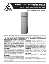
Adjusting Precharge
Prior to Installation
All well tanks are shipped with a standard precharge
of 38 psig.
Step 1. Remove protective air valve cap
Step 2. Check precharge pressure should be + or -
10% of the factory setting)
Step 3. Release or add air as necessary to make
the precharge pressure 2 psig below
the pressure switch pump cut-in setting.
(Example, if you have a well tank with
a precharge of 38 psig, and you have
a pressure switch setting of 30/50 psig,
adjust precharge of your well tank from 38
psig to 28 psig.)
Step 4. Replace protective air valve cap. Peel off
backing of label and apply over air valve
cap.
Explosion Hazard. Failure to follow
these instructions can cause a
rupture or explosion possibly causing serious or fatal
injury, flooding, and / or property damage.
System Connection
1. Locate your well tank in the final desired location.
2. Level as necessary.
3. To eliminate friction loss, do not reduce the pipe size from the
pump to the well tank.
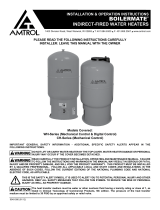
Start Up
Fine Tuning Procedures
Many times the actual pressure switch will vary from the standard
pressure range indicated. These variations could cause a momentary
lag of water delivery, as the pressure switch is not “tuned to the well tank
precharge pressure”.
1. Fill the system and well tank until pump cuts off.
2. Open one or more fixtures to drain the well tank.
3. If there is a momentary pause in the water flow from the time the well
tank is emptied and the pump starts, adjust pump cut-in setting clock-
wise slightly (see figure 2).
4. Close fixtures and refill well tank to pump cut off. Check time to fill.
5. Open fixtures and see if pause in water is eliminated. If not, con-
tinue adjusting pressure switch.
FIGURE 2
Pressure Adjustment Clockwise
To Increase Cut-Out Pressure
Counter Clockwise To
Decrease Cut-Out Pressure
Adjusting Precharge After Installation
Step 1. Drain tank of all water. Check precharge pressure in the
well tank.
Step 2. Release or add air as necessary to make the precharge
pressure 2 psig below the pressure switch pump cut-in setting.
AIR V A L V E
LABEL
AIR
V A L V E
CAP
AIR V A LVE LABEL
IN POSITION
OVER CAP
FIGURE 1
-4-
Page is loading ...
Page is loading ...
Page is loading ...
Page is loading ...
Page is loading ...
Page is loading ...

38 IPPC
(2.7 Kg/cm2)
AL TANQUE
HIDRONEUMÁTICO
UNIÓN
VÁLVULA
DE CORTE
AL SISTEMA
INTERRUPTOR
DE PRESIÓN
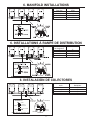
TUBERÍA TÍPICA DEL COLECTOR AL TANQUE
TUBERÍA PRINCIPAL
DRENAJE
MANÓMETRO
INTERRUPTOR
DE PRESIÓN
VÁLVULA
DE ALIVIO
DRENAJE
TUBERÍAS DEL DISTRIBUIDOR
38 IPPC
(2.7 Kg/cm2)
38 IPPC
(2.7 Kg/cm2)
38 IPPC
(2.7 Kg/cm2)
Tamaño mínimo
de la
1
1 1/4
1 1/2
2
Tubería del
distribuidor
17
30
40
60
Taille min de tuyau
de distribution
1
1 1/4
1 1/2
2
Gallons/minute
17
30
40
60
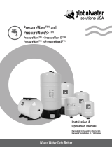
6. INSTALACIÓN DE COLECTORES
6. MANIFOLD INSTALLATIONS
6. INSTALLATIONS À RAMPE DE DISTRIBUTION
-11-
Minimum Manifold
Pipe Size
1
1 1/4
1 1/2
2
GPM
17
30
40
60

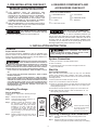
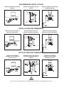
RECOMMENDED INSTALLATIONS
Well tank installed on-line with
jet pump.
Shallow well jet pump mounted
on tank.
Well tank installed on-line using
submersible pump.
RELIEF VA LV E
PRESSURE SWITCH
DRAIN
PERMISSIBLE
PRESSURE
SWITCH
LOCATION
DRAIN
UNION
FROM WELL
TO SYSTEM
UNION - 2 REQUIRED
PUMP
PERMISSIBLE
PRESSURE
SWITCH
LOCATION
#161 OR
#165
PUMP
STAND
SHUT-OFF
V A L V E
INSTALACIONES RECOMENDADAS
Tanque hidroneumático
instalado con una bomba de
chorro en línea.
Bomba de chorro para pozo de
poca profundidad montada en
el tanque
Tanque hidroneumático
instalado con una bomba
sumergible en línea.
INSTALLATIONS RECOMMANDÉES
Réservoir de puits installé en
ligne avec pompe à jet.
Pompe à jet pour puits peu
profond, montée sur réservoir.
Réservoir de puits installé en
ligne avec pompe submersible.
ÉVACUATION
RACCORD UNION
EN PROVENANCE DU PUITS
EN PROVENANCE DU PUITS VERS LE SYSTEME
RACCORD UNION - 2 NÉCESSAIRES
POMPE
EMPLACEMENT
ACCEPTABLE DU
PRESSOSTA T E
SUPPORT DE POMPE
N˚ 161 OU N˚ 165
SOUPAPE
D'ARRÊT
EMPLACEMENT
ACCEPTABLE DU
PRESSOSTA T E
MANOMÈTRE
PRESSOSTA T
SOUPAPE
DE DÉTENTE
ÉVACUATION
VERS LE
RÉSERVO IR
DE PUITS
POMPE SUBMERSIBLE
1400 Division Road, West Warwick, RI 02893 T: 401.884.6300 F: 401.885.2567 www.amtrol.com
-
 1
1
-
 2
2
-
 3
3
-
 4
4
-
 5
5
-
 6
6
-
 7
7
-
 8
8
-
 9
9
-
 10
10
-
 11
11
-
 12
12


Amtrol 100 PSIG User manual
- Type
- User manual
- This manual is also suitable for
Ask a question and I''ll find the answer in the document
Finding information in a document is now easier with AI
in other languages
- français: Amtrol 100 PSIG Manuel utilisateur
- español: Amtrol 100 PSIG Manual de usuario
Related papers
-
Amtrol EXTROL AX-20(V User manual
-
-
-
-
Amtrol 143-327 Installation guide
-
-
-
-
-
Other documents
-
none 141N43 Installation guide
-
 Water Worker 513P01 Installation guide
-
 Water Worker UNVDKT Operating instructions
-
 BoilerMate WH-41Z-B User manual
-
 Water Worker ERTG120-A Operating instructions
-
 globalwater solutions PWN‐US‐80LV Installation guide
-
Gledhill BoilerMate II Owner's manual
-
-
-


