
SCATIR Switch
User Guide
Model # 51150
SCATIR Switch with Sensor
Model # 51200
SCATIR Switch with Eyeglass Mounting Kit
Model # 51250
SCATIR Switch with Gooseneck Mounting Kit
Model # 51300
SCATIR Switch Deluxe

2
Table of Contents
Introduction
page 3
Description
Front of Sensor Box page 4
Back of Sensor Box page 5
Bottom of Sensor Box page 6
Operation
Dip Switches page 7
Adjusting Activation Distance page 7
Self Calibrating Mode page 8
Manual Calibrating Mode page 9
Auditory Tone page 10
Power page 11
Mounting
Gooseneck page 12
Eyeglass page 13

3
Introduction
The Self-Calibrating Auditory Tone Infrared (SCATIR) Switch is a multi-
purpose momentary-contact optical switch with auditory feedback designed for
use by persons who experience difficulty in activating mechanical switches. It
works by detecting a beam of reflected pulsed infrared light. It is suitable for use
with a variety of movements, including eye-blink, eyebrow movement, finger
movement, head movement or facial muscle movement. The controlling body
part does not need to be in physical contact with the switch sensor.

4
Description
1. Front of Sensor Box
Relay Out: Plug the relay cable into this port. It connects directly to the
device you want to control.
Relay On: This green light is on as long as the relay is closed/switch
closure occurs.
Valid: The valid light flashes three times when the unit is turned
on, when the dip switches are changed or the mode is set.
To Sensor: The end of the sensor plugs into this port.
Mode/Status: Flashes when switch closure occurs.
Sens Power: The red light blinks continuously as long as the sensor box has
power.
Off/On: Slide to off position when not in use.
Charge: The light stays on while the unit is being charged.

5
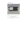
2. Back of Sensor Box
12/24 VDC: Plug the 12V charger into this port to charge the
internal 9V rechargeable battery.
Battery: This is a rechargeable 9 volt battery that has been
installed for you.

6
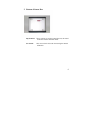
3. Bottom of Sensor Box
Dip Switches: These switches are used to control the tone, the sound
of the tone and the calibration mode.
Set Switch: This recessed switch is used when setting the manual
calibration.

7
Operation
1. Dip Switches
On the bottom of the unit you will find 4 dip switches or four small white
switches. These switches are used to control the tone, the sound of the tone and
the calibration.
Up is on. Down is off.
Beep On SW1 Up
Beep Off SW1 Down
Continuous Tone SW2 Up
Beep Tone SW2 Down
Manual Calibration SW3 Up
SW4 Down
Self Calibration SW3 Down
SW4 Up
2. Adjusting Activation Distance
The maximum distance allowed for activation (“activation distance”) can be
adjusted from a few centimeters to less than a millimeter. This adjustment can
be made manually or automatically (self-calibration), as explained below. When
the activation distance is reduced to its minimal value, the switch simulates a
zero force touch switch. When activation distance of, say, four centimeters, is
chosen, the switch can be activated from as far away as four centimeters.

8
3. Self Calibrating Mode
When the switch is being activated by a body part that cannot always maintain a
constant activation distance from the sensor, the switch can be operated in self
calibrating mode. In this mode, placing the activating body part at ANY given
distance within range of the switch will serve to define that distance as the
activation distance. Once activated at this distance, the switch may be turned off
by moving the body part completely out of the range of the sensor.
To set the self calibrating mode:
1. Turn the sensor box off.
2. Set the dip switches to: SW3 Down
SW4 Up
3. Position the sensor.
4. Place the body part in front of the sensor.
5. Turn the sensor box on.
Once activated the switch will be turned on by moving the body part any where
within the range of the sensor.

9
4. Manual Calibrating Mode
When in manual calibrating mode, the activation distance is set by the user.
1. Turn the sensor box off.
2. Set the dip switches to: SW3 Up
SW4 Down
3. Position the sensor.
4. Place the activating body part just beyond the desired activation
distance.
5. Turn the sensor box on.
6. Press the set switch beside the Dip Switches with the end of a pencil
until you hear three beeps and the valid light flashes three times.
7. The manual calibrating mode is now set.

10
5. Auditory Tone
The switch incorporates an auditory tone which emits a beep when the switch is
activated. This auditory feedback can be enabled or disabled by means of a dip
switch. The user can select either of two auditory feedback modes:
Beep Tone Mode:
A short momentary beep is emitted to indicate
activation. The relay light remains on throughout the
full period of activation.
Continuous Tone Mode:
A tone is emitted which lasts as long as the switch is
activated. The relay light remains on throughout the
full period of activation.

11
Power
Rechargeable Battery
To recharge the Nickel Metal Hydride (Ni/MH) battery in the SCATIR switch,
plug the power unit into the charger jack labeled “12-24 VDC” on the back of
the SCATIR switch. The yellow LED on the front of the box lights up to
indicate that the charging current is going into the battery. The charging time for
a fully discharged battery is 8 hours with the SCATIR switch turned on or off.
Do not attempt to charge non-rechargeable batteries. Do not plug the
charger into the SCATIR switch if a non-rechargeable battery is installed.

12
Mounting
1. Gooseneck Mounting Option
The SCATIR switch gooseneck sensor is equipped with a standard 5/8 – 27
thread. The kit comes with a variety of clamps and couplers to assist you in
mounting the gooseneck. The kit includes:
• ABS Plastic Mounting Plate
• Adhesive-backed Velcro ®
• Quick Release Gooseneck Mount assembly
• X-saddle
• Self Tapping Screws (#10, 1 inch long,
Phillips, flat head)
• Band Clamp
• Multi-bit Screw Driver
For more mounting information please go to this site:
http://www.msu.edu/~artlang/SCATIR_Gooseneck/Goosenec
k%20Mount%20Kit%20Guide2.pdf

13
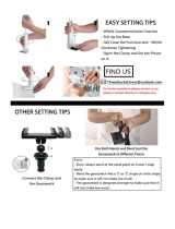
2. Eyeglass Mounting Option
This kit comes with the sensor clamped in a typical position on a set of eyeglass
frames. The eyeglass mounting may need to be adjusted to make it work well for
the individual user.
The kit includes:
- Two Allen wrenches (5/64”)
- Polyurethane bushings
- Sensor Clamp assembly, including two-part polished stainless steel
clamp, socket head cap screws (2-56), polyurethane bushing and
polyurethane protective grommets.
- Adhesive backed polyurethane tape
- Eyeglass frames
- Angled-head infrared sensor cable
*You may wish to remount the sensor on another pair of frames. The mounting
kit provides additional materials to clamp the sensor in place on different
frames. The angled head sensor may be mounted on flat surfaces, under clear lap
trays, or on surfaces of wheelchair armrests or headrests. These alternate
mounting sites can be used for sensing moving hands, fingers or other body
parts.
If the sensor is not pointed at the correct angle, use the following tips to bend the
sensor.

14
The angled-head sensor is constructed so that the wire leads and the plastic
insulation may be bent. Imbedded in the right-angle sensor is soft wire that helps
the sensor to stay in position after bending. This permits easy adjustment for
pointing the sensor towards the body part that is used for operation of the
SCATIR switch. The sensor head may be re-angled by simply grasping the end
of the sensor and pushing and bending it into place.
If the sensor is attached to the temple with the stainless steel clamp when you
attempt to bend it, you may need to loosen the clamp a bit and pull the head of
the sensor a small amount away from the clamp to allow more freedom for
bending it.
If you need to reshape the sensor with a large adjustment follow these directions.
• Warm the sensor with a hair dryer.
• Point the hair dryer at the sensor for one minute
• The heat softens the plastic and makes it more flexible.
• Grasp the end of the sensor and bend it into its new shape.
• Hold it in place while it cools.
June 2005
Tash International Tash Inc.
1-91 Station Street 3512 Mayland Court
Ajax, ON Richmond, VA
L1S 3H2 Canada 23233 USA
tf 800.463.5685 tf 800.463.5685
t 905.686.6895 t 804.747.5020
f 905.686.6895 f 804.747.5224
www.tashinc.com
-
 1
1
-
 2
2
-
 3
3
-
 4
4
-
 5
5
-
 6
6
-
 7
7
-
 8
8
-
 9
9
-
 10
10
-
 11
11
-
 12
12
-
 13
13
-
 14
14


Tash SCATIR 51300 User manual
- Type
- User manual
- This manual is also suitable for
Ask a question and I''ll find the answer in the document
Finding information in a document is now easier with AI
Other documents
-
 MAGIPEA ZJ10-1 User manual
-
 Enabling Devices 3706 User manual
-
 Enabling Devices 1550W User manual
-
 TEL AFA4000/1 Installation guide
-
Genie GS-3384 User manual
-
Robertshaw SMART 2000 Digital Programmable Thermostat Installation guide
-
MSA Toxgard® II Gas Monitor Owner's manual
-
 Q Core Sapphire User manual
-
 Oridion Capnostream 20p User manual
-
Enabling Devices 9008 User manual


