Page is loading ...

INSTALLATION INSTRUCTIONS
69-2460EFS-03
CQ8000A Universal Hot Surface
Igniter Kit
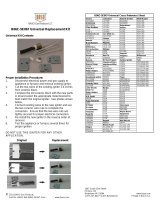
APPLICATION
The CQ8000A Universal Hot Surface Igniter Kit is designed to
provide a robust field service replacement igniter in gas fired
appliances with Norton/St Gobain 120 VAC silicon carbide hot
surface igniters. The CQ8000A uses a 120 volt silicon nitride
igniter design with long life and high resistance to damage or
burn out in the appliance. The kit includes the specially
designed silicon nitride igniter and six different bracket
configurations to adapt the igniter to the specific appliance
application along with accessory parts to allow mounting and
wiring the igniter. Clear instructions and application templates
are provided to simplify selection of the proper bracket and
ease installation of the replacement.
BEFORE YOU START
1. Review this instruction sheet fully to ensure you are
familiar with the steps and information necessary to
complete the installation properly, including the
WARNING section on this page.
2.
Confirm the existing hot surface igniter has failed:
a. Run an appliance cycle and observe the installed
igniter.
b. If the igniter glows, the problem is not the igniter.
c. If the igniter does not glow during an ignition cycle:
(1) Unplug the igniter lead wires.
(2) Set a voltmeter’s scale to 300 VAC and connect
the voltmeter to the igniter harness.
(3) Run another cycle and confirm 120 VAC power
at the harness during the igniter warm up time.
3. Check the appliance construction and wiring diagram
(typically located on an appliance panel) and confirm
that the appliance does not use the hot surface igniter
as the flame sensor. Do not use the CQ8000A kit if the
existing igniter is also the flame sensor. Use an original
equipment part. The CQ8000A is not designed to be
used as a flame sensor.
4. If the appliance is a sealed combustion model,
determine if the existing hot surface igniter ceramic is
part of the sealing of the burner box. If it is, check
carefully to determine if this kit will allow the proper
appliance function.
5. Confirm the kit components:
a. six brackets stamped A, B, C, D, E, and F
b. one hot surface igniter with wiring leads
c. two wire nuts and a thread forming screw
6. The CQ8000A should not be handled by the black
silicon nitride igniter. Use care to handle the CQ8000A
by the ceramic casing or the bracket.
INSTALLATION
When Installing This Product…
1.
Read these instructions carefully. Failure to follow them
could damage the product or cause a hazardous condition.
2.
Check the cross-reference table on page 4 and the tem-
plates (Fig. 1 and Fig. 2) to make sure the proper igniter
bracket is used for your application.
3.
This product is intended for installation by a trained and
experienced service technician. If a service technician is
not available, the individual installing this product must
be knowledgeable in the design, construction, and
operation of the gas fired appliance being serviced.
4.
After installation is complete, check out appliance
operation as provided in these instructions.
WARNING
Fire or Explosion or Electrical Shock Hazard.
Can cause severe injury, death or property
damage.
1. Never install where water can flood, drip or
condense on the igniter or its controller.
2. Liquefied petroleum (LP) gas is heavier than air
and will not naturally vent upward.
— Do not operate electric switches, lights, or
appliances until you are sure the appliance area
is free of gas.
3. Disconnect power supply before beginning wiring
or making wiring connections to prevent electrical
shock or equipment damage.
4. The CQ8000A is NOT designed to replace silicon
carbide hot surface igniters in residential gas ovens or
residential clothes dryers. Use of this product in a
residential gas oven or residential gas clothes dryer
can result in severe injury, death, or property damage.
Remove the old igniter assembly
1.
Turn off electrical power supply external to the appliance.
2.
Turn off gas supply to the appliance.
3.
Set thermostat to the lowest setting or OFF.
4.
Remove the appliance panel to expose the burner area.
If necessary remove the burner box panel to expose the
installed igniter.
5.
Disconnect the installed igniter from the appliance wiring
harness and move the wiring harness out of the way.
6.
Carefully review the location of the installed igniter in the
appliance. Pay attention to where the igniter is located
relative to the burners and other parts of the appliance.
This will help confirm the location of the new igniter for
installation.
7.
Locate and remove the screw(s) holding the installed
igniter or igniter bracket assembly in place. Remove the
installed igniter very carefully to avoid damaging it.
Retain the screw(s) for re-installation.

CQ8000A UNIVERSAL HOT SURFACE IGNITER KIT
69-2460EFS—03 2
NOTE: If there is an orange rubber gasket on the original
metal bracket, carefully remove the gasket from the
original bracket and use it with the CQ8000A bracket
E to support the replacement.
Select the proper CQ8000A bracket
1. Use the cross-reference table to determine which igniter
models are recommended for replacement. See Table 1
on page 4.
2.
Using the bracket selection templates (Fig. 1 and Fig. 2),
the cross-reference (Table 1), and the original igniter
assembly, place the igniter on the templates to confirm
which bracket to use for this installation.
NOTES:
1. Each of the six brackets has a letter stamped on it
(A through E) for easy identification.
2. If bracket A is selected, use pliers to remove
either Tab 1 or Tab 2 at the score line per the
bracket template directions.
3. If bracket E is selected, ensure that the original
orange gasket (if present) is reused.
3.
Install the Universal igniter into the selected bracket using
the provided thread forming screw.
NOTE: In some appliance applications, installation may be
easier if the bracket is installed in the appliance first,
then the igniter added to the bracket. As the thread
forming screw for the bracket takes some force for ini-
tial tightening, start the screw in the bracket to set the
threads, remove the screw, attach the bracket to the
appliance using the original screw(s), and then attach
the igniter and its thread forming screw to the bracket.
Install the replacement igniter
1. Carefully position the replacement igniter and bracket
assembly into the appliance. Position the assembly so
the existing mounting screw holes align with the mount-
ing holes or slots in the replacement assembly.
2.
Secure the replacement igniter bracket with the original
igniter screws. The CQ8000A brackets are designed with
the capability to make minor adjustments in the igniter
location. Use care to adjust the igniter hot spot to a posi-
tion where it will light reliably.
NOTE: In some applications, a shorter screw may simplify
installation.
3.
Orient the replacement igniter the same way as the origi-
nal igniter was positioned and secure it. Be sure the igniter
portion does not touch the appliance or burners.
4.
Carefully route the replacement igniter lead wires away
from the burner flame and any moving parts on the com-
bustion air blower in the appliance.
5.
Locate the appliance igniter wiring harness. Clip off the
connector and strip both wires to 1/4 in. (6 mm).
6.
Use the provided wire nuts to attach the igniter lead wires
to the appliance wiring harness. The igniter lead wires can
be cut shorter if desired. Strip them to 1/4 in. (6 mm) prior
to attaching to the appliance wire harness.
Check out the installation
1. Recheck location of the igniter bracket assembly and
lead wires to assure there is no interference and that
the lead wires will not be exposed to excessive heat or
moving parts when the appliance is firing.
2.
Recheck the line voltage connections between the igniter
harness and the appliance wiring harness to be sure they
are secure. Assure that no bare wire is exposed at this
connection.
3.
Turn the electrical power supply on, but leave the gas
supply off, and initiate a light off (call for heat) cycle.
Observe the hot surface igniter during the sequence to
confirm it gets hot and that there is sufficient clearance
between the igniter and other appliance parts. Also
confirm that the lead wire routing does not interfere with
appliance operation.
4.
Remove the call for heat signal.
5.
Turn the gas supply on.
6.
Initiate a call for heat. Observe the light off sequence and
confirm that the appliance lights properly and stays lit once
the actual gas flow starts.
7.
If the appliance lights and the main flame stays stable,
remove the call for heat and allow the shut down
sequence to be completed. Repeat step 6 two more times
to assure the light off of the appliance is reliable.
8.
If the appliance does not light properly, it may be neces-
sary to adjust the location of the hot surface igniter. Each
CQ8000A bracket is designed to allow some adjustment of
the igniter location in the appliance. Turn the gas supply off
then loosen the mounting screw(s) and make adjustments.
Retighten the screw(s) and repeat from step 5. It may be
necessary to repeat this process a few times in order to
determine a position where the igniter will light reliably.
Fig. 1. Igniter bracket B template; dimensions in in. (mm).
Modèle de support d'allumeur B; dimensions en pouces (mm).
Plantilla del soporte B del encendedor; dimensiones en pulgadas (mm).
PLACE REMOVED IGNITER OVER TEMPLATE OUTLINE
PLACER L’ALLUMEUR RETIRÉ SUR LE TRACÉ DU MODÈLE
COLOQUE EL ENCENDEDOR EXTRAÍDO SOBRE EL CONTORNO DE LA PLANTILLA
MFS28764
USE BRACKET B
UTILISER LE SUPPORT B
UTILICE EL SOPORTE B
2-3/16 (56)
B
BRACKET B
SUPPORT B
SOPORTE B

CQ8000A UNIVERSAL HOT SURFACE IGNITER KIT
3 69-2460EFS—03
Fig. 2. Igniter brackets A, C, D, E, and F template; dimensions in in. (mm).
Modèles de support d'allumeur A, C, D, E et F; dimensions en pouces (mm).
Plantilla de los soportes A, B, C, D, E y F del encendedor; dimensiones en pulgadas (mm).
A
1
2
PLACE REMOVED IGNITER OVER TEMPLATE OUTLINE
C
D
BRACKET A
SUPPORT A
SOPORTE A
REMOVE TAB 2.
RETIRER LA LANGUETTE 2.
QUITE LA LENGÜETA 2.
REMOVE TAB 1.
RETIRER LA LANGUETTE 1.
QUITE LA LENGÜETA 1.
E
ORANGE GASKET
JOINT ORANGE
JUNTA ANARANJADA
TAB 2
LANGUETTE 2
LENGÜETA 2
TAB 1
LANGUETTE 1
LENGÜETA 1
PLACER L’ALLUMEUR RETIRÉ SUR LE TRACÉ DU MODÈLE
COLOQUE EL ENCENDEDOR EXTRAÍDO SOBRE EL CONTORNO DE LA PLANTILLA
REUSE ORANGE GASKET FROM IGNITER BEING REPLACED.
RÉUTILISER LE JOINT ORANGE DE L’ALLUMEUR À REMPLACER.
UTILIZAR LA JUNTA ANARANJADA DEL ENCENDEDOR QUE SE REEMPLAZARÁ.
1
MFS32190
F
USE BRACKET F.
UTILISER LE SUPPORT F.
UTILICE EL SOPORTE F.
REMOVE TAB 1.
RETIRER LA LANGUETTE 1.
QUITE LA LENGÜETA 1.
METAL BRACKET
SUPPORT EN MÉTAL
SOPORTE DE METAL
2-5/32 (54)
2-5/16 (58)
2-5/16 (58)
2-5/16 (58)
2-5/16 (58)
2-5/16 (58)
2-5/16 (58)
1
BRACKET F
SUPPORT F
SOPORTE F
BRACKET C
SUPPORT C
SOPORTE C
BRACKET D
SUPPORT D
SOPORTE D
BRACKET E
SUPPORT E
SOPORTE E

CQ8000A UNIVERSAL HOT SURFACE IGNITER KIT
69-2460EFS—03 4
Table 1. CQ8000A bracket selection.
a
Sélection de support pour CQ8000A.
Selección del
soporte del CQ8000A.
a
Table data is correct to the best of Honeywell's knowledge as of this publication's date. However, some appliances may have
igniter applications that are beyond the capabilities of this kit.
Les données du tableau sont correctes à la connaissance de Honeywell à la date de publication. Toutefois, certains appareils
peuvent avoir des applications d'allumeur d'une portée supérieure aux capacités de ce nécessaire.
Los datos de la tabla son correctos según el leal saber y entender de Honeywell en la fecha de esta publicación. Sin embargo,
es posible que algunos artefactos tengan aplicaciones de encendedor que superan las capacidades de este kit.
b
For igniters that require bracket A, use the template (Fig. 2) to determine the tab to be removed.
Pour les allumeurs nécessitant le support A, utiliser le modèle (Fig. 2) pour déterminer la languette à retirer.
Para los encendedores que requieren el soporte A, utilice la plantilla (Fig. 2) para determinar la lengüeta que se debe quitar.
c
For Carrier sealed combustion furnaces, you must use bracket E and retain the existing orange gasket for use with bracket E.
Pour les appareils à combustion scellés Carrier, utiliser le support E et conserver le joint orange existant pour l'utiliser avec le
support E.
Para los sistemas de calefacción de combustión hermética Carrier, debe utilizar el soporte E y guardar la junta anaranjada para
utilizarla con el soporte E.
Mfr. OEM #
CQ8000A
Bracket
b
Mfr. OEM #
CQ8000A
Bracket
b
Mfr. OEM #
CQ8000A
Bracket
b
Mfr. OEM #
CQ8000A
Bracket
b
American
Road
Equip.
201W A
Hupp
Industries
09050 A
Robert-
shaw
41-402 A
Weil
McLain
511-330-139 B
Arco Air
1096048 D Intercity 1009604 D 41-403 B 511-330-190 B
1380680 D 1096048 D 41-404 B 511-330-193 B
Armstrong
Air
38322B001 A Majestic 75-92-104 A 41-405 A White LB 120-07549 A
Carrier/
Bryant/
Payne
LH33ZS001
B or E
c
75-92-105 A 41-407 B
White-
Rodgers
767A-301 A
LH33ZS001A
Metzger
201N A 41-408 A 767A-303 F
LH33ZS002 201W A 41-409 B 767A-306 A
LH33ZS002A Modine 5H76032A C 41-410 A 767A-311 A
LH33ZS003
Mor-Flo
3200618 A 41-412 D 767A-350 A
LH33ZS003A 511-330-193 B 41-418 C
LH33ZS004
Nordyne
105141000 A
Snyder
General
1380654 B 767A-353 F
Claire Bros.
C-238 A 632-0770 A 1380672 B 767A-354 A
C242 A 632-0880 A 767A-357 F
Coleman
1474-051 A
Norton/
St Gobain
201 B 1380680 B 767A-361 A
1474-052 A 271 B
Superior
Fireplace
94851 A 767A-364 A
Comfort
Maker
1096048 D 201D A Tempstar 1096048 D 767A-366 A
Detroit
Radiant
201D A 201K A
Trane
340039P01 A 767A-370 B
DMO Ind. 20834 A 201L A B138196P01 B 767A-371 A
Dornback
Furnace
271W A 201N A B144676P01 A 767A-372 A
Ducane 20015201 B 201R A B144676P02 B 767A-373 D
Enero Tech 10399 A 201W A B340039P01 A 767A-376 B
Evcon
1474-051 A 271N A IGN23 A 767A-377 A
1474-052 A 271NM D IGN26 B 767A-382 B
Evcon
Coleman
025-32625-000 B 271P A IGN30 B Williamson 9050 A
Goodman
B1401009 D 271W A IGN34 A
York
025-27766-000 A
B1401018 C Raypak 600915 B Viessman 9302-094 A 025-27774-000 A
B1401018S D Rheem 62-22441-01 A Wayne
Home
Equip.
62821-001 A 025-29043-000 A
HB Smith 50018 A
Roberts
Gordon
90434300 B 62821-002 A 025-29050-000 A
Heil 1096048 D 90436600 A
/