Page is loading ...

The Savant
®
Remote Plenum Sensor measures the air temperature discharged
from a commercial HVAC system. The CLI-PLEN1C commercial type sensor is
mounted to a UL rated metal electrical box and is attached to the plenum
ductwork using self-tapping screws.
The CLI-PLEN1C is wired to the CLI-8000/8000A Thermostat Processing Unit
(TPU) using a two-wire Cat 5 twisted pair or equivalent cable. At the TPU, the
Plenum sensor is plugged into the REMOTE SENSORS connection located on
the front panel. At the sensor side, the sensor is wired to the remote sensor
cabling using the Dolphin Splice Connectors enclosed in the install kit.
Once mounted, the Max and Min DAT (Discharge Air Temperature) setting
within the HVAC menu of the TPU can be adjusted for Min and Max values. If
either of these settings are crossed, the heating or cooling system is shut down.
Box Contents
(1) CLI-PLEN1C
(2) Dolphin Splice Connector (028-0581-xx)
(1) Quick Reference Guide (this document)
Related Components
Savant
®
CLI-8000/8000A Eight Zone Centralized Thermostat Processing Unit
Savant
®
CLI-PLEN1R - Residential Type Plenum Sensor
Savant
®
CLI-THFM1 - Remote Humidity/Temperature Smart Sensor
Savant
®
CLI-SLAB1 - Remote SLAB or floor heating sensor
Savant
®
SST-TEMP1 - Remote Indoor Temperature Sensor
Savant
®
SST-OTEMP1 - Remote Outdoor Temperature Sensor
CLI-PLEN1C
Specifications
Environmental
Environmental
Temperature
32° to 158°F
Cable Requirements
Cable Requirements
Cat 5 (24 AWG)
500 feet (152.4 m) maximum
Sensor Property & Features
Sensor Property & Features
Temperature Range
(Thermistor)
-94° to 302°F
Temperature Accuracy
(Thermistor)
+/- 0.36°F
Probe Length
12 inches (304.8 mm)
Probe Material
Stainless Steel
Probe Wire Length
8 inches (203.2 mm)
Probe Housing (l x w)
4 inches (101.6 mm) x 2.125 inches (53.975 mm)
Probe Housing Depth
1.625 inches (41.28 mm) Including Cover
Probe Housing Depth
1.5 inches (38.1 mm) No Cover
Probe Wire Properties
FT4, 176°F (80°C), 600V
Compliance
Compliance
RoHS
Compliant
Installation
1. Position the Plenum temperature sensor between the evaporator coil in the
furnace and the bypass zone dampers on one of the supply trunks. Refer to
the diagram below. The Plenum temperature sensor should be mounted in
the shaded area in the diagram below.
2. In the area selected, drill a ⅝ inch hole into the ductwork.
3. Slide the sensor into the hole.
4. Add a small amount of high temperature silicone glue between the electrical
box and where the box mounts to the ductwork. This will prevent any
possible air leaks.
5. Insert (2) #6 self-tapping screws (not included) through the holes in the
bottom of the electrical box and screw them into the ductwork. Refer to the
diagram below.
Wire Sensor to Remote Sensor Cabling
1. Connect the wires from the sensor to the existing remote sensor cabling
using the Dolphin Splice Connectors enclosed in the install kit. There is no
polarity observed here.
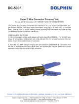
Important Note: It is recommended that the Dolphin Ratcheting Crimp Tool
DR-4141 or DC-500F be used to terminate the connections.
Connection at CLI-8000/8000A
1. Remove the four position screw terminal from the REMOTE SENSORS
connection of any zone on the TPU. The Plenum sensor is supported on
port 2 only.
2. Loosen the screws located on the top of the connector till the silver crimp in
the front opens enough to slide the wire from the remote sensor cabling into
the connector.
3. Insert the wires from the Remote Sensor cabling into the terminal block. No
polarity is observed here.
4. Turn the screws clockwise till the silver crimp clamps around the wire. Tug
on the wire a bit to verify the wires are installed securely.
5. Plug the terminal block back into its remote sensor mate in the front panel.
6. Configure the CLI-8000/8000A to enable communications between the
sensor and the TPU.
Additional Information
Once the sensor is installed, it needs to be configured and if required,
calibrated. For information related to configuring and calibrating or any other
information related to installing and configuring the Savant Centralized Climate
Control system, refer to the Savant Portal at dealers.savantsystems.com
Knowledge Base > Savant Hardware > Climate Control
Savant
®
Centralized Climate Control Deployment guide (009-1073-XX, CLI-8000)
Savant
®
Centralized Climate Control Deployment guide (009-1154-XX, CLI-8000A)
Copyright © 2014 Savant Systems, LLC. SAVANT and RacePoint Blueprint are trademarks of Savant Systems, LLC.
All brand names, product names and trademarks are the property of their respective owners.
Savant Systems, LLC reserves the right to change product specifications without notice.
Savant
®
Remote Plenum Temperature Sensor
(CLI-PLEN1C-00)
Quick Reference Guide
Scan this QR code for additional
product information.
009-1100-02
CLI-PLEN1C-00
009-1100-02
31314
Savant Confidential and Proprietary
1
of
1
/
